1. Introduction
The performance of internal combustion engines has improved significantly, with reduced emissions and fuel consumption, partly due to the widespread use of turbochargers. However, malfunctioning turbochargers can cause oil, thermal, or vibration issues [
1]. While experimental methods on test benches offer accurate assessments of rotor displacement, they are costly. To lower expenses, simulations that provide realistic results are widely used. This study conducted a stationary modal analysis of a turbocharger rotor via both measurement and simulation.
The Campbell diagram, essential for analyzing turbocharger rotor stability, highlights critical speeds where natural frequencies align with excitation frequencies. Identifying these critical speeds helps predict excessive vibrations and potential rotor failure. Prior research [
2,
3] extensively used Campbell diagrams to analyze turbocharger rotors, focusing on critical speeds, vibration modes, and rotor reliability under varying conditions.
While the existing literature provides valuable insights into turbocharger rotordynamics, a gap exists in research specifically investigating the influence of rotor, bearing, and lubricant parameter modifications on Campbell diagrams and their corresponding vibration modes. In a study by B. Schweizer [
4], the influence of floating bearing ring spring stiffness on gyroscopic mode shapes was investigated for stiffnesses of 3000, 15,000, and 150,000 N/mm. The initial value of 3000 N/mm was determined through simulations relating mean bearing forces to mean shaft displacements during run-up.
Figure 1 summarizes the results. As expected, natural frequencies generally increase with higher bearing stiffnesses, except for the fifth mode, which is identified as torsional. Interestingly, every second mode up to the fifth exhibits a more significant frequency increase. This phenomenon could be attributed to the presence of reverse and forward pair modes. These mode pairs, such as conical or translational modes, typically originate from the same natural frequency at zero rotor speed (0 rpm). As the speed increases, they diverge in a V-shape, with the reverse mode decreasing in frequency and the forward mode increasing. Motivated by these observations, this article aims to explore and summarize the specific impact of various influencing factors on the natural frequencies of the investigated rotor.
2. Materials and Methods
The simulations were conducted using the ROSS Python library, which facilitates the creation of rotor models and numerical simulations [
5]. Compared to commercial rotordynamic software, ROSS offers several advantages for investigating turbocharger rotor stability. First, its open-source nature allows for the customization of models and algorithms to precisely reflect the specific rotor design under investigation. Second, ROSS provides granular control over simulation parameters, enabling the exploration of a wider range of values for key factors like rotor mass and lubricant properties. This level of control fosters a deeper understanding of the underlying rotordynamic principles governing critical speeds and vibration modes. In addition to these benefits, ROSS performs the assembling of the global matrices for the system and utilizes the general form of the equation:
Here, M represents the mass matrix, C(Ω) is the damping matrix dependent on the rotational speed Ω, ωG is the gyroscopic matrix, and K(Ω) is the stiffness matrix also dependent on Ω, while f(t) refers to external forces acting on the system. This formulation allows for accurate simulation of the rotor dynamics, including the effects of gyroscopic forces, damping, and stiffness variations.
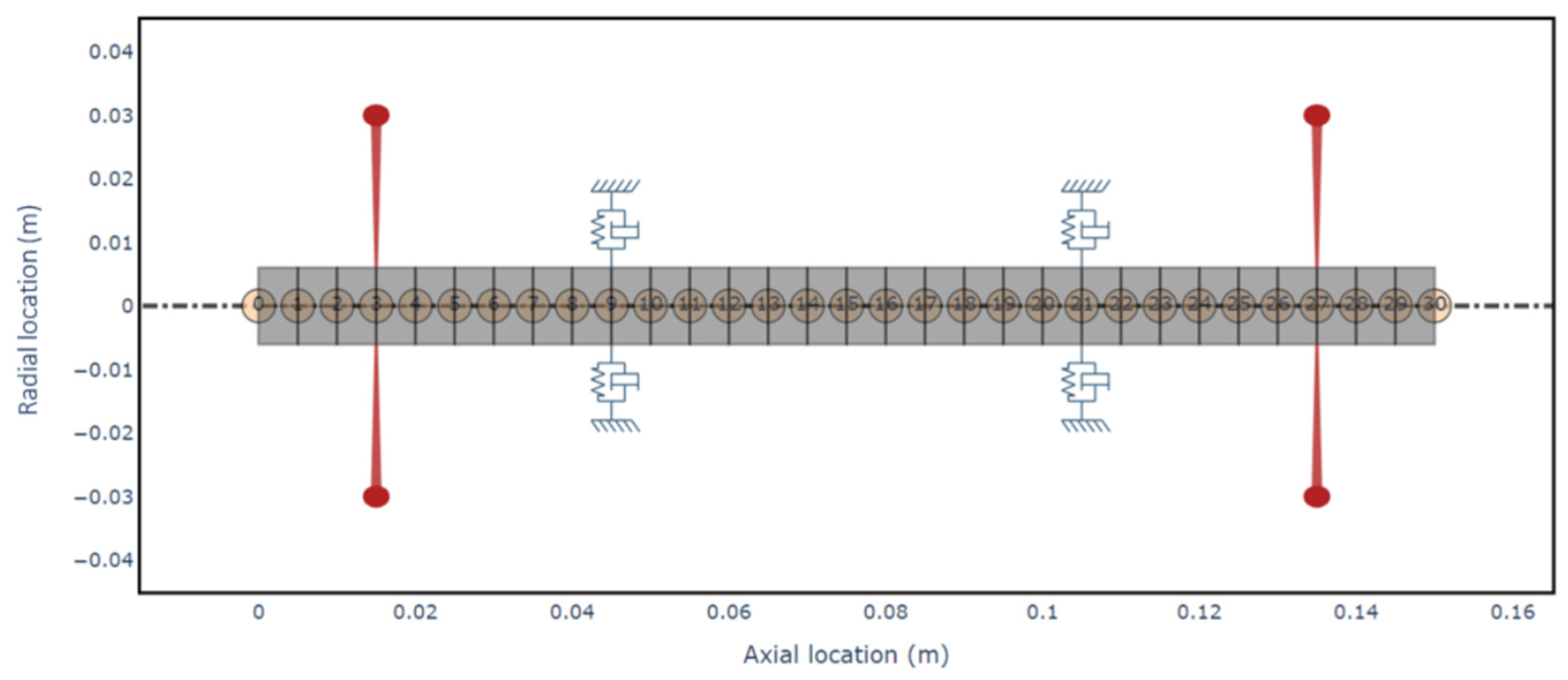
While the ROSS library offers a variety of application tutorials, a dedicated turbocharger model was not included. Therefore, this article leverages a rotor model from the COMSOL Multiphysics’ Application Gallery, titled “Turbocharger Supported on Floating Ring Bearings” [
6]. The model consists of a turbocharger rotor supported by two floating ring bearings, one located near the compressor and the other near the turbine, with both the compressor and turbine overhung on the shaft. This configuration, which includes a beam rotor and floating ring bearings implemented through multiphysics couplings, aligns closely with our institute’s research objectives on rotor-bearing-lubricant interactions. The model was created with multiplied nodes, defining 30 nodes on the rotor to provide opportunities for changing bearing positions with high flexibility. The Python script defined material and rotor properties in list format, along with shaft, bearing, and disk elements. Compressor and turbine wheels were modeled as disks with specified mass, inertia values, and their positions on the shaft. To simulate the hydrodynamic journal bearing, ROSS utilizes the “BearingFluidFlow” element, which generates frequency-dependent coefficients for each analyzed frequency value. Finally, the script assembled the shaft, disks, and bearing elements, and the resulting model is presented in
Figure 2.
With all rotor parameters defined in the model, the Campbell diagram can be generated.
Figure 3 illustrates the Campbell diagram for the initial model. The horizontal axis (
x-axis) represents the rotational speed in radians per second (rad/s), while the vertical axis (
y-axis) shows the calculated natural frequencies, also in rad/s. The first-order frequency is depicted by a blue dot-dashed line. Wherever this line intersects a natural frequency curve, a critical speed marker is indicated.
As previously mentioned, vibration modes are typically visualized as diagonal lines originating from the natural frequency at 0 rpm on the left side of the plot. These lines then progress in a V-shape, representing the forward and backward modes evolving with increasing rotational speed.
For subsequent analyses, only the critical frequencies of the identified modes will be presented. This approach allows for a more concise presentation within the confines of this article.
3. Results and Discussion
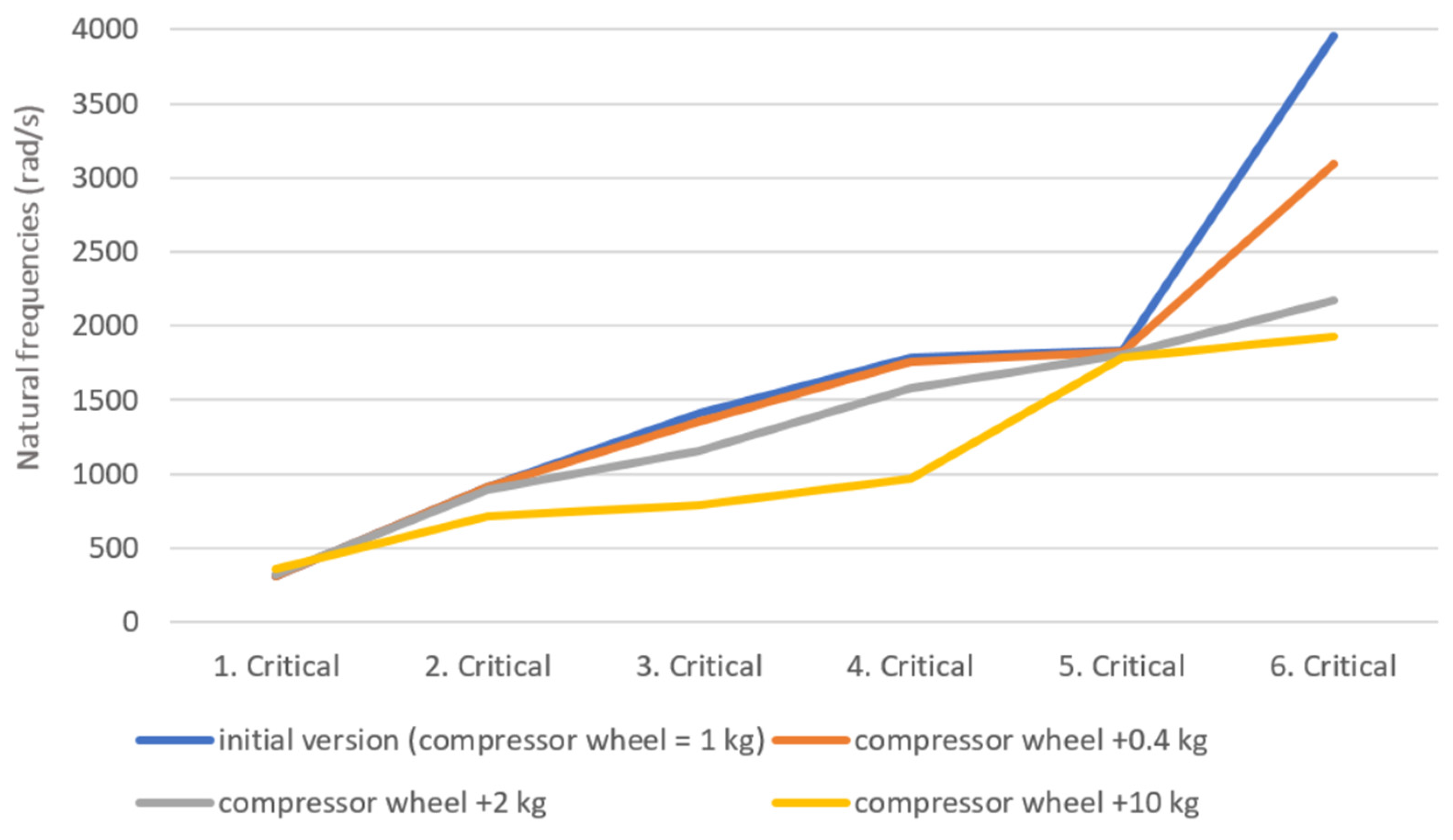
To guide further research efforts, three distinct simulation iterations were conducted, focusing on specific rotor parameter variations. The first iteration investigated the influence of compressor wheel mass changes. This approach has real-world justifications, which can be based on soot deposition or damages.
Figure 4 presents the critical speeds of the rotor, similar to
Figure 1. However, unlike
Figure 1, it does not depict the mode shape frequencies at a specific rotational speed. Instead, it focuses on the critical speeds, which occur when the first-order critical speed line intersects the various natural frequency curves. The initial modification involved increasing the compressor wheel mass by 0.4 kg, matching the mass of the turbine wheel. Subsequent modifications used larger mass increments to observe more pronounced effects. As expected, increasing compressor wheel mass generally lowers the natural frequencies. The first and fifth modes exhibit minimal changes, potentially due to their torsional nature. However, a slight decrease can still be observed. Notably, the sixth mode shows the most significant decrease, suggesting that bending modes are most affected by compressor wheel mass changes. This aligns with the expectation that bending modes induce larger displacements at the rotor ends, particularly the compressor wheel.
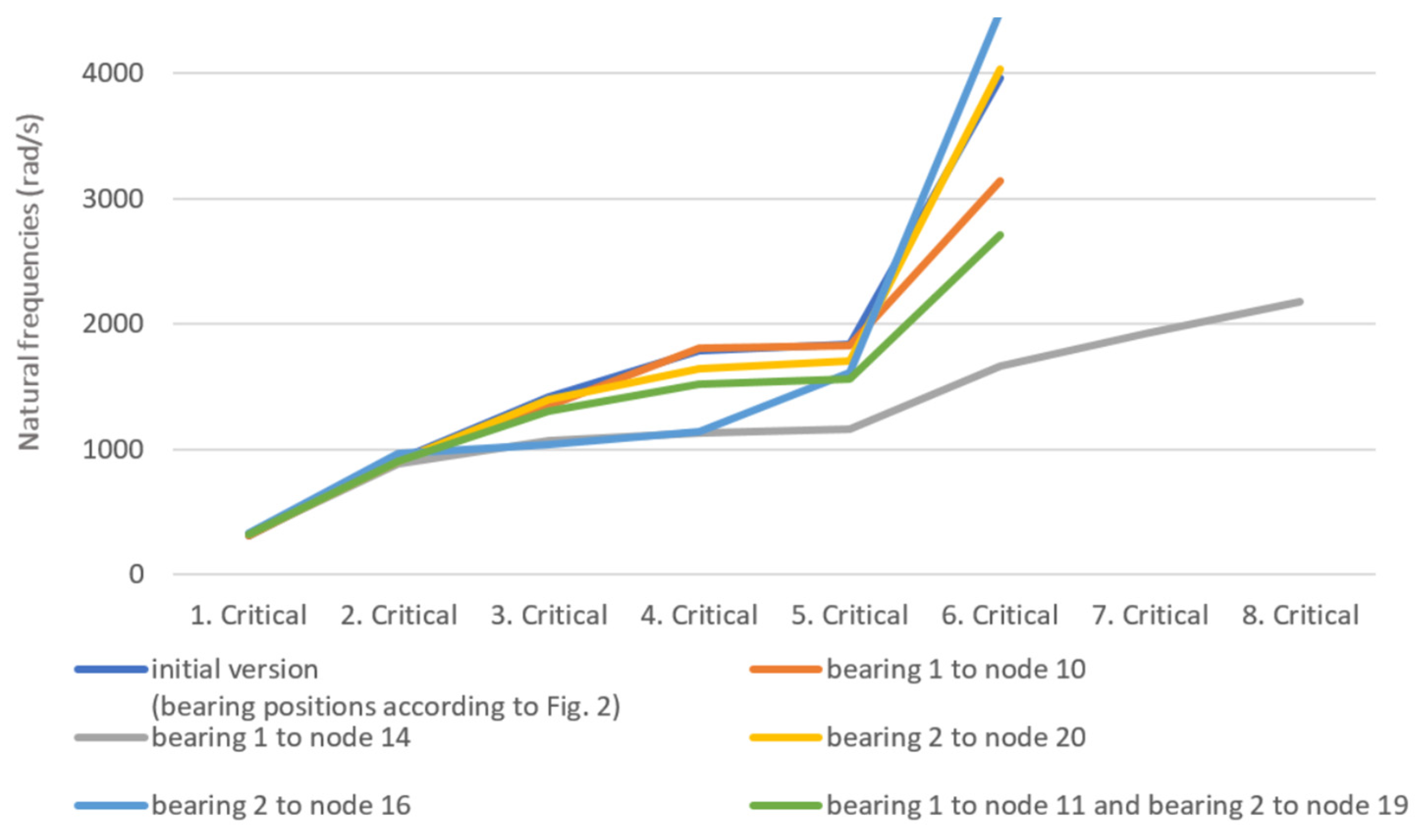
The second investigation explored the influence of bearing positioning, a crucial rotordynamic parameter during rotor design. As observed in
Figure 2, the initial model features symmetrical bearing placement, which is uncommon in real-world turbochargers. To investigate the impact of the bearing position,
Figure 5 presents five different iterations compared to the baseline. In this figure, “bearing 1” refers to the compressor-side bearing, and “bearing 2” refers to the turbine-side bearing.
The initial iterations involved moving each bearing one node closer to the shaft’s center. These adjustments resulted in minimal changes to the critical speeds. Subsequently, both bearings were shifted five nodes away from their original positions, bringing them closer to the shaft’s center. This modification, particularly on the compressor side, yielded the most significant effect, introducing two additional critical speeds. This phenomenon might be attributed to the overall axial imbalance of the rotor. The turbine wheel’s larger mass necessitates a counterbalancing load on the opposite side, which the bearing placement might be affecting. Finally, the last iteration involved moving both bearings two nodes closer together. This configuration led to lower critical frequencies, which often indicates compromised rotordynamic performance.
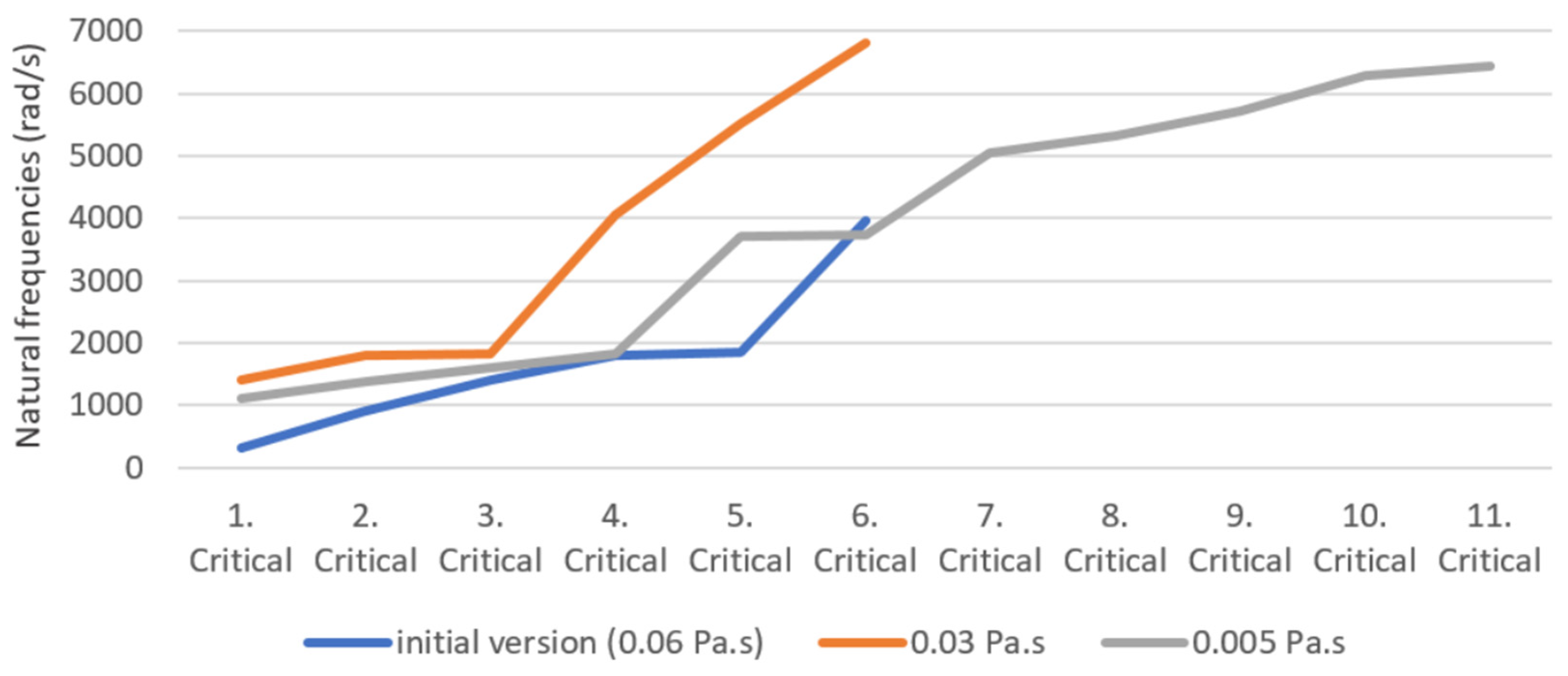
The final series of simulations focused on lubricant properties, a key research area for our institute that will be further investigated through future test bench experiments. Lubricant viscosity is a critical factor in turbocharger operation. The current trend is to reduce viscosity to minimize frictional losses, thereby improving efficiency and reducing emissions for a given power output. However, this comes at the expense of increased wear, the potential for inadequate lubrication, and ultimately, earlier component failures. The turbochargers under investigation typically operate with 0W-20 engine oil, offering a dynamic viscosity of 0.045 Pa·s at 40 °C, which decreases to 0.0084 Pa·s at 100 °C [
7]. In contrast, modern 0W-8 hybrid engine oils exhibit a much lower viscosity, with values of 0.026 Pa·s at 40 °C and a mere 0.005 Pa·s at 100 °C [
8]. The initial model in our simulations was set to a viscosity of 0.06 Pa·s, as specified in the COMSOL model. This value was then progressively reduced in two iterations, reaching 0.03 Pa·s and 0.005 Pa·s, respectively. The results of these simulations are presented in
Figure 6.
As expected, the 0.03 Pa·s case exhibited increased critical speeds, indicating enhanced rotor stability. However, the 0.005 Pa·s case resulted in five additional critical speeds due to the introduction of a highly unstable, wavy mode curve that intersects the first-order speed line multiple times at higher rotational speeds. It is important to acknowledge that the COMSOL model rotor might not represent a typical passenger car turbocharger due to the wheel masses, potentially reflecting a commercial vehicle design. Nevertheless, this simulation effectively demonstrates the significant impact that low-viscosity lubricants can have on critical speeds and, consequently, on rotor stability.


