Abstract
Gas blow-by flow through a turbocharger sealing system has a significant effect on lubricant consumption and the formation of particles. This paper presents an experimentally validated computational model to quantify the mass flow of gasses through a sealing system as a function of operating conditions. The computational model is applied to a truck engine turbocharger and the results are verified experimentally. The results show that the gas blow-by is not only influenced by the geometrical parameters of the lubrication system but is controlled by the thermo-mechanical loading of the turbocharger, with a non-negligible influence of the radial dynamics of the rotor.
1. Introduction
The problem of negative emissions from internal combustion engines (ICEs) in the transport sector is serious and needs to be addressed. In addition to reducing fuel consumption and CO2 emissions, it is important to address the production of particulate matters, which are produced by both diesel [1] and petrol ICEs [2]. Turbochargers (TCs) are used to increase power and reduce ICE fuel consumption [3], but they also cause gas leakages, known as gas blow-by (GBB), which can contaminate the lubricant located in the central housing. The contamination of the lubricant by gasses can lead to speed up wear and the loss of lubricant properties. These gas leaks are a growing problem with the modern trend towards using TCs with increasing pressure ratios [4].
In principle, when higher pressures occur in the central housing, a lubricant can leak back into the compressor or turbine with the gas flow through the sealing systems, which is particularly noticeable at low rotor speeds and therefore low compressor pressures, often when there are problems with lubricant draining from the central housing. This phenomenon, called gas blow-back, transfers lubricant into the compressor or turbine, which is then partially burned, increasing the production of particulate matter [5] and unburned hydrocarbons [6,7]. The piston group is usually the dominant source of lubricant consumption, but lubricant consumption caused by TCs is an inherent and undesirable consequence of operating turbocharged ICEs. A TC’s lubricant consumption can be reduced by limiting the gas blow-back flow, which has a positive effect on the overall lubricant consumption and reliability of the ICE. A key element is then the TC sealing system, which uses flexible sealing rings to control GBB and gas blow-back flows.
The control of GBB by the turbocharger sealing system depends on understanding its mechanisms and predicting them under operating conditions. The aim of the research is therefore to understand these mechanisms by using computational simulations and subsequently enable targeted designs to reduce GBB. These designs have the secondary effect of reducing lubricant consumption and particle transport to the compressor or turbine, where they can be deposited and reduce efficiency or burned and increase harmful emissions.
2. Material and Methods
2.1. Computational Model for Gas Blow-by Solution
It is clear that the GBB depends not only on the pressures in the individual chambers of the TC sealing system, such as the central housing, chambers defined by grooves and rings or the compressor and turbine backplate chamber, but also on the shape of the labyrinth between these chambers.
The computational model must therefore solve a coupled problem involving structural dynamics, fluid dynamics and heat transfer. Such a model can be designed in a variety of ways, from simple (zero-dimensional) 0D approaches to complex three-dimensional (3D) computational approaches. The fact that the given physical phenomena are time-dependent is certainly a complication. The proposed computational model represents a certain balance between the physical depth and physical width of the problem and combines different levels of computational models in terms of dimensionality.
The central module of this computational model is the so-called virtual turbocharger, which was developed and verified by the authors Novotný et al. [8]. This model uses a 3D description of the turbocharger rotor and a fast hydrodynamic model of the floating ring journal bearing. A very important sub-model is the computational model of the thrust bearing, and for a solution of GBBs, the model presented in the work of Novotný et al. [9] is used.
The 3D computational model constructed in this way was extended by a 0D computational model of the gas dynamics in the labyrinths of the sealing system on the compressor side and on the turbine side. This model is based on the assumption that the gas flow through the sealing system can be with some minor simplifications considered a one-dimensional (1D) flow of a fully transient nature. In the simulations of long-time operations of a TC, the model developed in this way proves to be a sufficiently accurate description of the given problem and very computationally efficient.
The computational model is also extended by a 0D thermal model describing the heat transfer through the rotor, taking into account the interactions from central housing through the lubrication film layers of the oil film bearings and the heat transfer from the compressor and turbine.
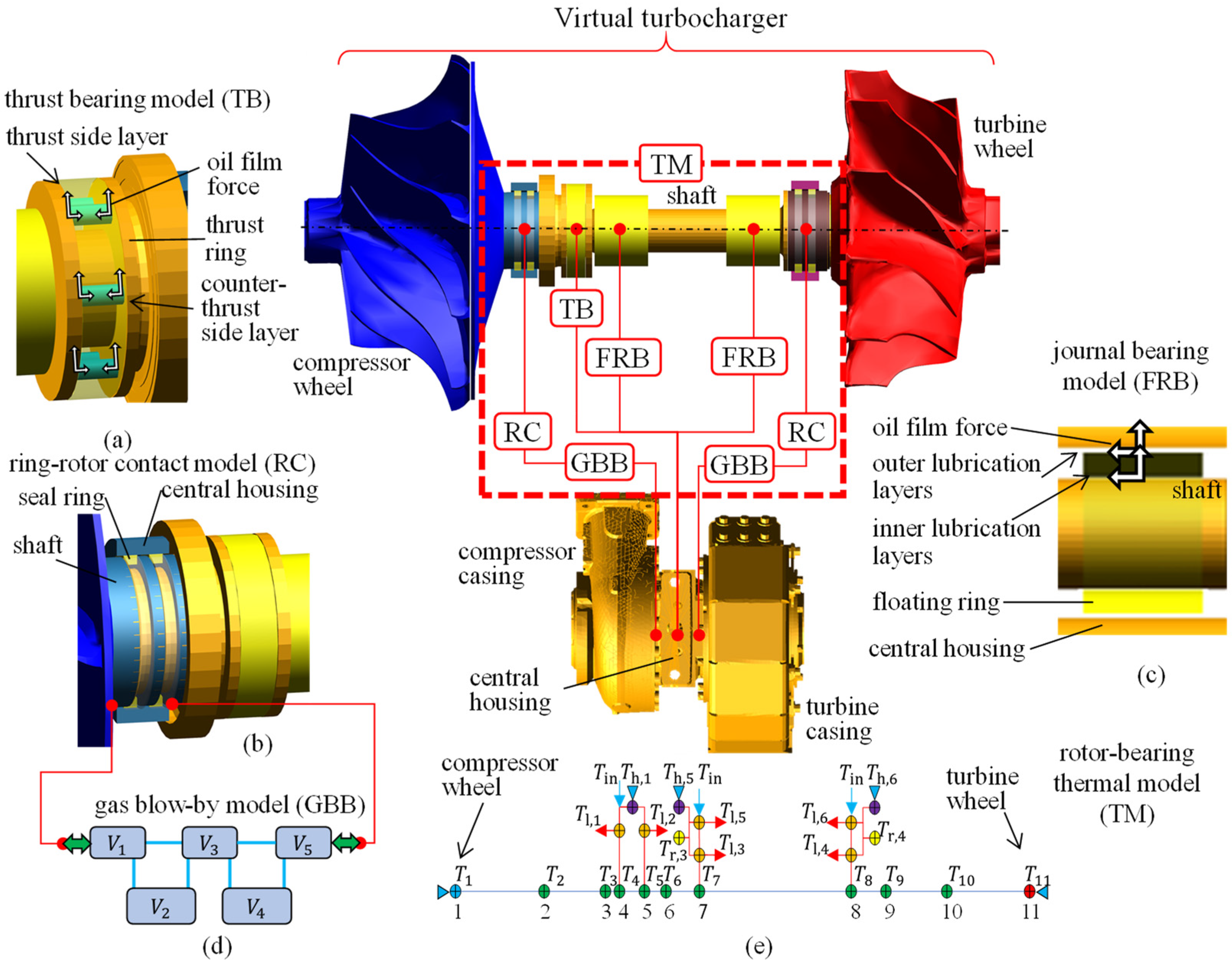
The computational model shown graphically in Figure 1, i.e., the virtual turbocharger, was assembled in the multibody system ADAMS and extended by user-written functions solving the 3D dynamics of the seal rings, the 1D model of the gas dynamics and the mass concentrated 0D model of heat transfer in solids. The computational model contained 30 rigid bodies with 3D geometry, two 3D bodies based on reduced finite element models, four mass points, 35 constraint joints, 12 differential equations for solutions of a ADAMS system of non-existent physical phenomena, 9 motion generators, four contact forces using 3D geometry, 28 general forces, and 734 solver variables and was controlled by 416 user parameters, and the definitions of the sub-models can be found in [10].

Figure 1.
Graphical scheme of the virtual turbocharger as a coupled computational model for the transient solution of rotordynamics using sub-models of the thrust bearing (a) [9], the ring–shaft interaction model (b) and the floating ring journal bearing model (c) [8]. The virtual turbocharger is extended by sub-models including the model of gas dynamics in the sealing system (d) and the rotor bearing thermal model (e).
2.2. Experimental Methods for Gas Blow-by Solution
The calculated values were verified by technical experiments on a test bench in the test cell. Basic quantities such as gas temperatures and pressures in front of and behind the impellers, oil film thickness of the thrust bearing and others were measured on the TC used for gas blow-by measurement. The TC was installed the diesel six-cylinder ICE with a power output of 260 kW under 2200 min−1.
The ICE was operated in a slow sped-up regime within 30 s (600–2400 min−1), and during this sped-up regime, the values of gas and oil temperatures, gas pressures and distances were measured using thermocouples, piezoresistive sensors and eddy current distance sensors. The GBB values were measured directly on the test bench for the entire TC using an orifice pressure differential device.
3. Discussion of Results
The computational model is designed to provide a wide range of different results from kinematic quantities and thermodynamic quantities to gas leakage through the sealing system. In the case of this paper, the focus is only on the evaluation of the GBB through the sealing system.
The GBB values are calculated in the time domain as a function of rotor speed. Figure 2 summarizes the GBB values calculated by the computational model, shows the compressor and turbine side components of the sealing system and compares these values with the measured values. The turbine side showed a significantly higher GBB than the compressor side, mainly due to the higher pressures in the turbine and the specific position of the seal rings within the shaft grooves. The GBBs on both sides gradually increased with increasing pressure ratios and reached very similar GBB values at high rotor speeds. At very high speeds, the compressor GBB was limited by regulation.
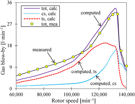
Figure 2.
Calculated (calc) total GBB and GBB components on the turbine (ts) and compressor (cs) side of the sealing system depending on the rotor speed. The calculated values are compared with the result of the technical experiment (mea), and the range marked for each measured value expresses the uncertainty of the measurement. The results are presented for the sped-up regime of the ICE with TC.
The results of the computational model and the technical experiment (Figure 2) show some differences, especially at very low speeds. This fact is influenced by the small value of GBB and therefore by the greater influence of other quantities that are not accurately influenced by the computational model.
4. Conclusions
Based on the analysis of the results of both calculations and experiments, it can be defined that the GBB through the TC sealing system is mainly dependent on the geometric configuration of the sealing system and the thermodynamic conditions at the turbine and compressor, respectively.
The geometry of the sealing system is determined not only by the geometry of the individual components (grooves, rings, etc.) but also by the motion of these components. The thermodynamic conditions on the rotor have a significant effect on the axial load on the rotor. The pressure conditions on the impellers cause the rotor to move and this changes the shape of the sealing labyrinth—the individual thin gaps change significantly. GBB through the thin gap between the seal rings and grooves is usually the dominant source of leakage. The axial movement of the rotor due to pressure conditions on the impellers can both reduce and increase GBB. The radial movement of the rotor also has a non-negligible effect on the GBB, which is amplified in the case of strong rotor resonances.
GBB through the ring lock is always present but is often very small due to the flow through the thin gap. The ring lock gas leakage is strongly influenced by the gas pressure gradient and gas temperature. The effect of rotor movement on this mechanism is minimal. There is one case where the influence of this mechanism is dominant, and that is when the thickness of the thin gap is limited when the ring is pressed against the groove wall.
The temperatures of the turbine and compressor also have a significant effect on the temperature distribution in the sealing system and thus on the properties of the flowing gas. Due to the very small geometric dimensions of the labyrinth, the gas almost adopts the temperature of the surrounding walls, changing its properties and resulting in a change in GBB.
The calculated and measured data show non-negligible discrepancies in GBB values, especially at low rotor speeds. These discrepancies are probably due to the imperfection of the thermal model for estimating the turbine wheel temperature due to heat transfer from the flue gas.
Author Contributions
Conceptualization, P.N.; methodology, P.N.; experimental data evaluation, P.K.; validation, J.V. and F.K.; formal analysis, J.V.; resources, P.K.; data curation, P.K.; writing—original draft preparation, P.N.; writing—review and editing, J.V.; visualization, P.N. All authors have read and agreed to the published version of the manuscript.
Funding
The research leading to these results has received funding from the Specific research program at the Brno University of Technology, reg. no. FSI-S-23-8235.
Institutional Review Board Statement
Not applicable.
Informed Consent Statement
Not applicable.
Data Availability Statement
Data for this study are not publicly available.
Conflicts of Interest
The authors declare no conflicts of interest.
References
- Sarvi, A.; Fogelholm, C.J.; Zevenhoven, R. Emissions from large-scale medium-speed diesel engines: Influence of engine operation mode and turbocharger. Fuel Process. Technol. 2008, 89, 510–519. [Google Scholar] [CrossRef]
- Qian, Y.; Li, Z.; Yu, L.; Wang, X.; Lu, X. Review of the state-of-the-art of particulate matter emissions from modern gasoline fueled engines. Appl. Energy 2019, 238, 1269–1298. [Google Scholar] [CrossRef]
- Feneley, A.; Pesiridis, A.; Andwari, A. Variable Geometry Turbocharger Technologies for Exhaust Energy Recovery and Boosting-A Review. Renew. Sustain. Energy Rev. 2017, 71, 959–975. [Google Scholar] [CrossRef]
- Dhariwal, H.C. Control of blowby emissions and lubricating oil consumption in I.C. engines. Energy Convers. Manag. 1997, 38, 1267–1274. [Google Scholar] [CrossRef]
- Lyu, X.; Liang, X.; Wang, Y.; Wang, Y.; Zhao, B.; Shu, G.; Tian, H.; Wang, K. Influence of lubricants on particulate matter emission from internal combustion engines: A review. Fuel 2024, 366, 131317. [Google Scholar] [CrossRef]
- Brandenberger, S.; Mohr, M.; Grob, K.; Neukom, H. Contribution of unburned lubricating oil and diesel fuel to particulate emission from passenger cars. Atmos. Environ. 2005, 39, 6985–6994. [Google Scholar] [CrossRef]
- De Albuquerque, P.C.C.; De Andrade Ávila, R.N.; Barros Zárante, P.H.; Sodré, J.R. Lubricating oil influence on exhaust hydrocarbon emissions from a gasoline fueled engine. Tribol. Int. 2011, 44, 1796–1799. [Google Scholar] [CrossRef]
- Novotný, P.; Škara, P.; Hliník, J. The effective computational model of the hydrodynamics journal floating ring bearing for simulations of long transient regimes of turbocharger rotor dynamics. Int. J. Mech. Sci. 2018, 148, 611–619. [Google Scholar] [CrossRef]
- Novotný, P.; Hrabovský, J.; Juračka, J.; Klíma, J.; Hort, V. Effective thrust bearing model for simulations of transient rotor dynamics. Int. J. Mech. Sci. 2019, 157–158, 374–383. [Google Scholar] [CrossRef]
- Novotný, P.; Kudláček, P.; Vacula, J. Explanation of the mechanisms of unsteady gas flow through the turbocharger seal system, including thermal and structural interactions. Propuls. Power Res. 2023, 12, 180–198. [Google Scholar] [CrossRef]

Disclaimer/Publisher’s Note: The statements, opinions and data contained in all publications are solely those of the individual author(s) and contributor(s) and not of MDPI and/or the editor(s). MDPI and/or the editor(s) disclaim responsibility for any injury to people or property resulting from any ideas, methods, instructions or products referred to in the content. |
© 2024 by the authors. Licensee MDPI, Basel, Switzerland. This article is an open access article distributed under the terms and conditions of the Creative Commons Attribution (CC BY) license (https://creativecommons.org/licenses/by/4.0/).