1. Introduction
Fuel cell technology is not new, and neither is the hydrogen storage option, but in the field of transportation, among electrified propulsion vehicles, most automobiles are fed from batteries [
1,
2,
3]. One of the reasons for this is the cost involved in the storage and auxiliaries, but also the volume of the overall system (which cannot be neglected). To offer a very compact fuel cell (FC) system with an appropriate balance of plant, the optimum fluid flows should be assured in the operation. Thus, for the FC reactants’ supply, special attention should be paid to the compressor subsystem [
2,
4].
When it comes to compressor applications, the ratings in terms of torque and speed are defined by the application. In
Figure 1, the main electromechanical applications on board of automobiles and their torque–speed ratings are presented. For the FC compressor system, the peak torque and speed ratings are in the range of 10 Nm 20,000 r/min. Now, a question could be raised with respect to the topology of the electric motor to be used: should it involve permanent magnets [
5,
6], be of the induction type [
7], or have variable reluctance [
8,
9]? Based on the scientific literature, but also based on our experience [
6,
7,
9], and also bearing in mind the cost issue, we have decided to develop a synchronous reluctance motor (SynRM). Similarly to the switched reluctance motor (SRM), the SynRM has no active rotor, magnets, or excitation coil. Hence, this investigation will mainly be focused on the mechanical consolidation of the rotor, while special attention should be paid to the heating of the bearings (a topic that is not discussed here). Nevertheless, the SynRM, in contrast to the SRM, has a better power density, since we are dealing with a three-phase a.c. machine. Moreover, a classic three-phase inverter can be used to feed the motor, so no supplementary investment is needed from this point of view (contrary to the SRM).
Besides the controllability issue, which can be affected by an inadequate torque characteristic, researchers should pay close attention to the SynRM’s performance.
(The meanings of the above abbreviations are as follows: EPAS—electric power-assisted steering; EAFS—electric-assisted front steering; EMB—electromechanical brake; SBW—shift by wire; HVAC—heating, ventilation, and air conditioner; FCAC—air compressor for fuel cell; EG—electric gear box; EHAS—electro-hydraulic active suspension; EMAS—electromechanical active suspension; EAT—electrically assisted turbocharger; VVT—variable valve timing; SG—starter–generator; EV—electric vehicle traction; HEV—hybrid EV propulsion/storage.)
When dealing with the performance of an electric motor, one should think about its efficiency and power factor. Anticipating this discussion, since our SynRM will have two poles, which offers the best possible power factor for a SynRM, we will need to evaluate the iron losses, which affect the efficiency of the motor [
10,
11]. High speeds involve high frequencies, and since the iron loss component is proportional to the square of the frequency and of the flux density, special care should be taken from this point of view. The FC is not considered to be a source of vibration and noise, but the presence of the compressor could affect the FC’s behavior. And our goal is to minimize the torque ripples as much as possible [
6]. These two issues will be investigated in this paper, i.e., the iron loss component and the torque ripples, while three main winding topologies will be considered. By means of a numerical investigation, based on the finite element method (FEM), the authors will investigate the electromagnetic behavior of a 7.5 kW/18,000 r/min SynRM to validate its suitability for the given application, the compressor of a FC system.
2. The Designed SynRM
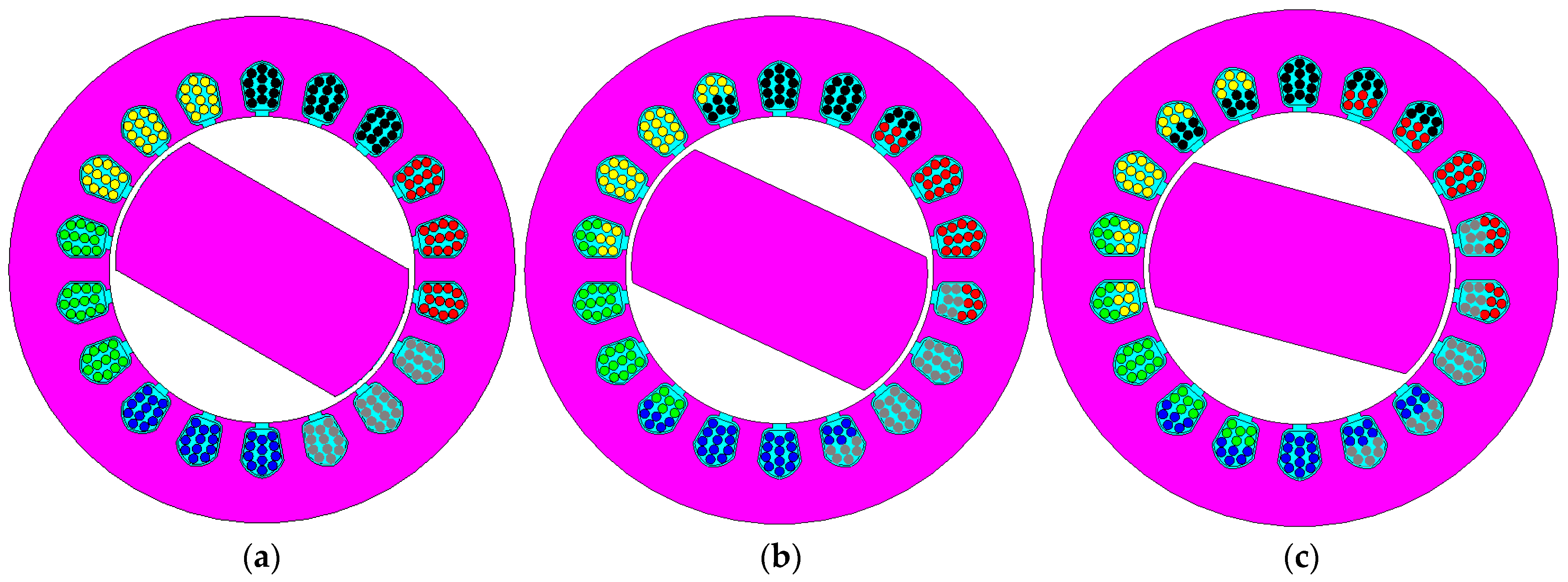
The designed SynRM comprises three phases, with 7.5 kW rated power and 18,000 r/min speed. Thus, a 4 Nm rated torque is our starting point, while the peak torque should be 2.5 higher, at the adequate current injection, and for a short period of time (the reason for not using higher speeds is due to the bearings: beyond an 18,000 r/min speed, special materials should be used for the bearings, with higher costs, and, as stated earlier, we do not want to allow for extra costs). In these conditions, the rated torque will be 3.97 Nm. The motor for the FC’s compressor will be supplied from the power battery of the EV/HEV; thus, we considered a 380 Vdc voltage for the three-phase inverter used to feed the compressor’s motor. Thus, an 18 Arms phase current was used for the calculations, as well as 155 Vrms for the phase voltage. To achieve a smooth sinusoidal voltage, we want to keep the rated frequency as low as possible. Consequently, we considered one pair of poles for our SynRM. Thus, the supplying frequency was 300 Hz, which means that through appropriate switching, we could assure the smoothest possible phase voltage (to limit the inverter’s commutation losses, at the given rated current, we opted for a switching frequency of 12 kHz). Also, the winding configuration plays an important role in the task of obtaining a smooth sinusoidal phase voltage and, consequently, reduced torque ripples. Since the machine has two poles, only a distributed winding configuration is possible for the stator, and we studied three configurations (see
Figure 2 and
Figure 3): one layer and a coil pan with nine slots; two layers and a coil span with eight slots; and two layers and seven slots for the coil span.
As expected, the winding coefficient of the last two variants is reduced, but improved harmonic content on the phase voltages is expected. The cross-section of the designed SynRMs, with a focus on the slot turns (study ready for thermal evaluation—not presented here) for the winding configuration is shown in
Figure 3. We want to evaluate the electromagnetic behavior of the machines using the electromagnetic approach, by using FEM, with the goal of validating which is best suited for the FC compressor application through simulations.
3. FEM Analysis and Validation
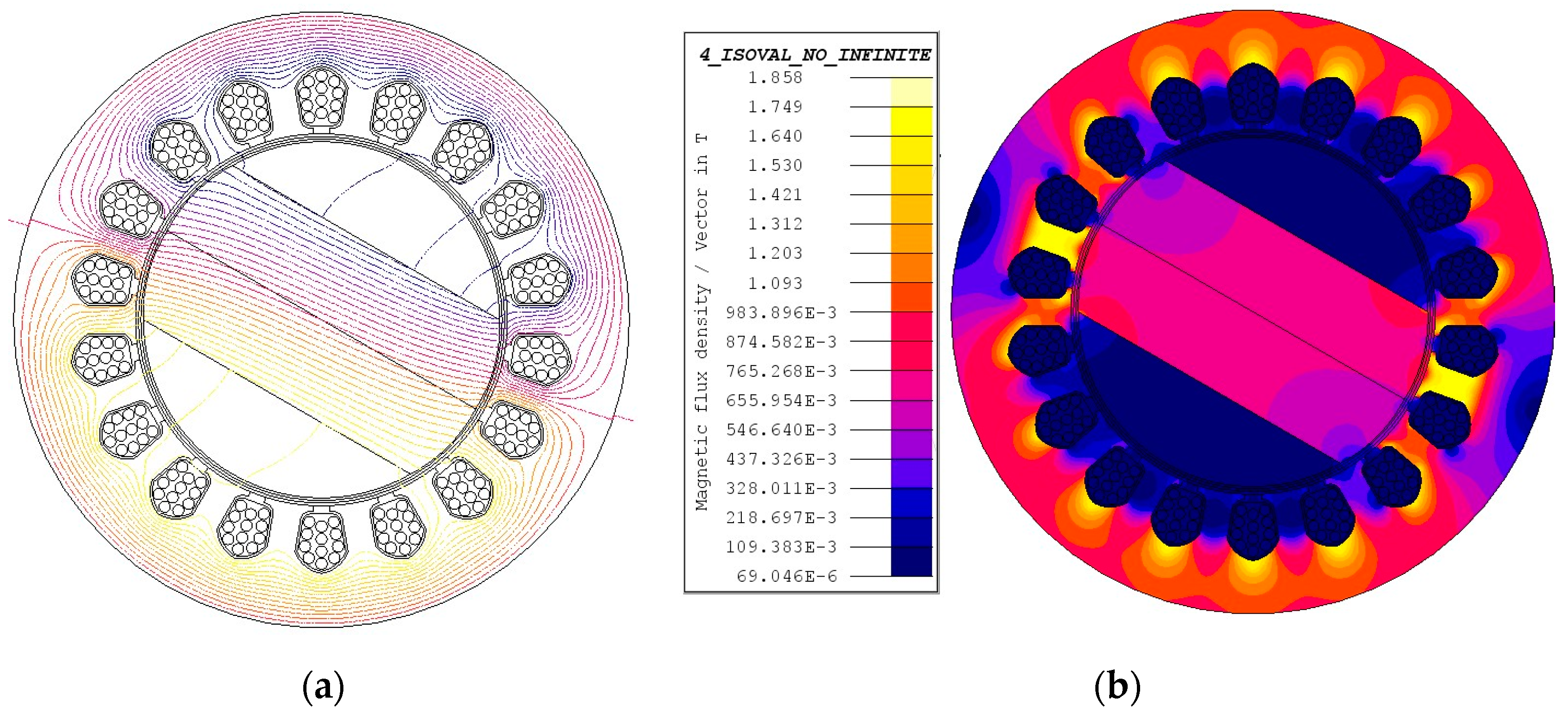
The electromagnetic behavior of the machine was evaluated through the finite element method (FEM) with Cedrat-Flux2D software. The three winding topologies were drawn in the software, while the active material properties were also introduced. Motor operation conditions were emulated while considering three-phase feeding of the motor’s phases, with the same rated current, 18 Arms/phase. The motor was parametrized with its inertia and a load torque of 4 Nm. A 96% good-quality mesh was obtained.
First, the field lines and the flux density within the active parts of the studied machine were evaluated to identify the saturation risk of the active iron of the machines (see
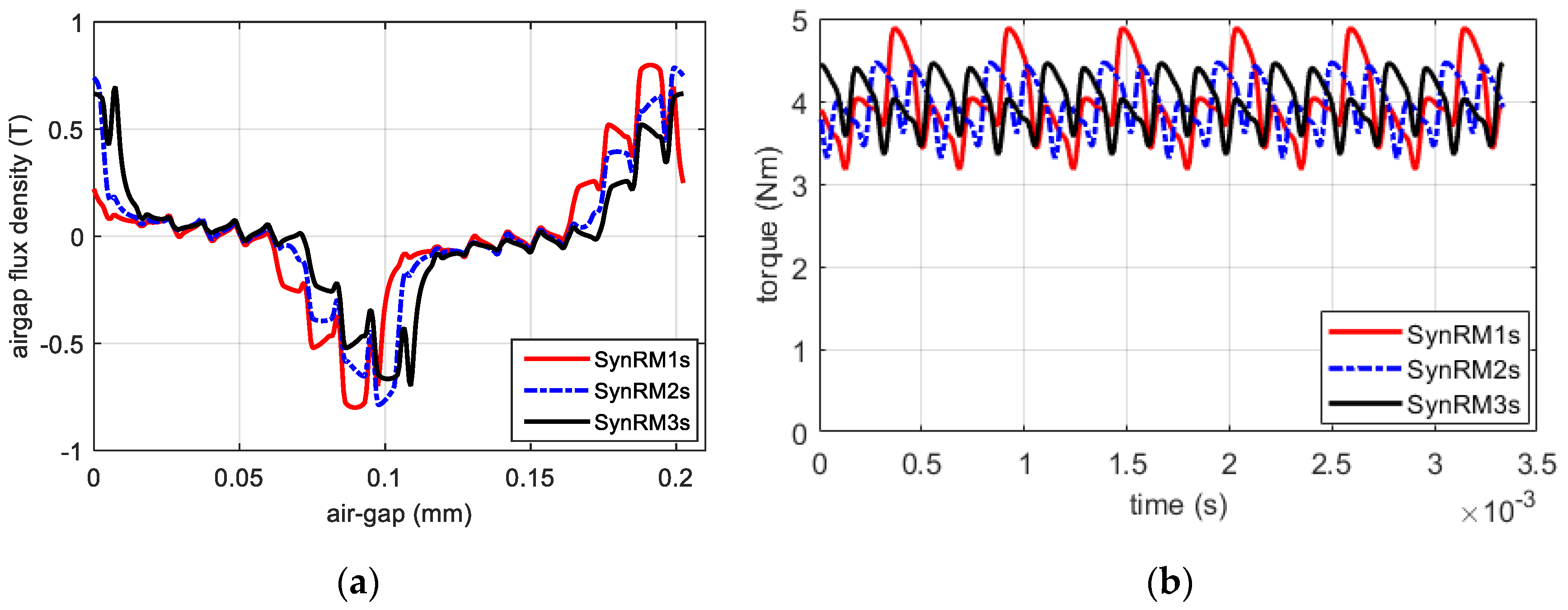
Figure 4). No abnormal behavior was found, and thus, the flux density air gap was computed for a pair of magnetic poles (see
Figure 5a). Expected oscillations were plotted, on the basis that such magnetic fluctuations justify the torque wave depicted in
Figure 5b. Just looking at the torque plot, the torque ripples look significant, but not of an abnormal shape, for an application for which the dynamics is not like traction motors.
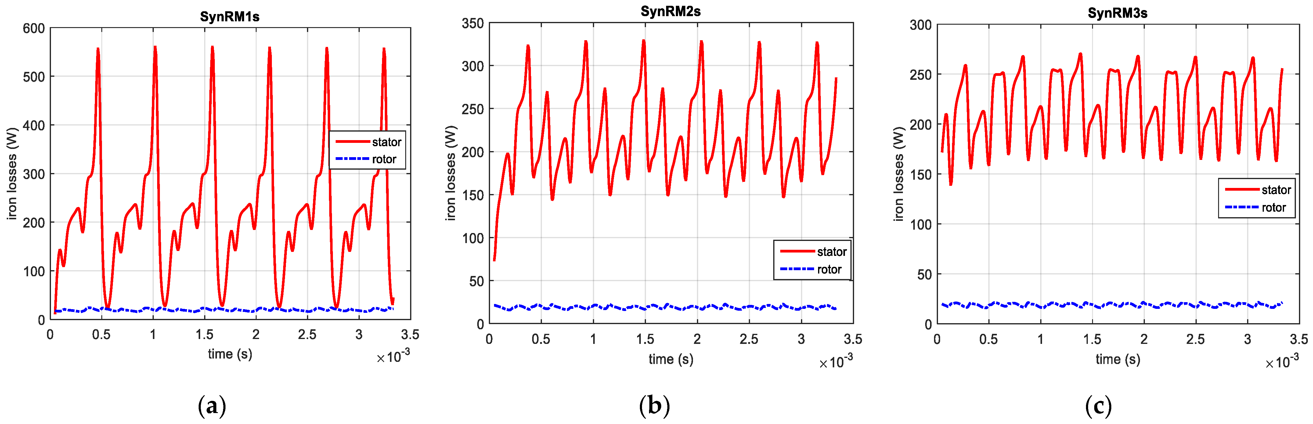
Next, we want to evaluate the iron losses within the active parts of the studied machines. Since we are operating at high speeds, the rotor iron loss component cannot be neglected (even if we are dealing with a synchronous type of machine). In
Figure 6, one can check the average iron loss values shown in
Table 1. We can say that all winding configurations produce similar iron losses, but since the first one manifests very high pics (
Figure 6a), it is expected that the torque ripples will be at their highest value. With respect to the iron losses, their values were numerically computed within the software, containing eddy and hysteresis loss components, based on the following parameters: hysteresis coefficient of 145.8 W·s·T
−2·m
−3; conductivity of 4 × 10
6 Ω
−1 m
−1; thickness of lamination of 0.35 mm; excess loss coefficient of 3.435 W·s
−1.5·T
1.5·m
−3; stacking factor of 0.97; and frequency of 300 Hz.
In
Table 2, a summary of the performances of the analyzed structures is depicted. As expected, the torque ripple of SynRMs1 is at the highest level, while the second and third analyzed variants present pretty much the same levels of iron losses. In terms of efficiency, SynRMs1 has 0.3% higher efficiency than SynRM3. At such a power level, this can be neglected, while 35.5% of the torque ripple improvement was found for the third SynRM topology, compared with SynRMs1. For the sake of comparison, a 4.5% torque ripple improvement was found compared with the SynRM2 variant, which could imply important advantage in terms of the vibration and noise sent towards the FC stack. With respect to the weight, the first variant is the lighter by 1 kg compared with the third one, while the cost is not significantly increased for the second and third variants. Thus, since efficiency is not much affected (only with 0.3%), while the weight and cost are in the same range, we intend to consider the SynRMs3 variant the best suited variant for our application.
4. Conclusions
In this paper, we have proposed a synchronous reluctance machine (SynRM) that is capable of operating at 7.5 kW and 18,000 r/min, dedicated to the fuel cell compressor application. Three winding variants were investigated: SynRMs1, with one layer and nine slots per coil span; SynRMs2, with two layers and eight slots for the coil span; and SynRMs3, with two layers and seven slots for the coil span. Based on the design parameters, we introduced the structure into a finite element analysis software, and we investigated, through simulations in a motor operating regime, the electromagnetic behavior of the studied variants. By looking at the iron loss component (and consequently at the efficiency) and, then, at the torque wave and its ripples, while evaluating the cost and weight of all topologies, we concluded that the SynRMs3 variant is the best suited for the given application.
As future work, the authors will investigate the option of skewing the rotor core or stator armature to further reduce the torque ripples. Such an approach will affect the power density of the high-speed machine, and a careful investigation should be considered to find the best compromise between torque ripple mitigation and the obtained power density, since we do not want to increase the weight and volume of the compressor system by too much.


