Proceeding Paper

Design and Construction of a Controlled Solid-State Relay with Variable Duty Ratio for DOMOTIC Applications †

Departamento de Automatización y Control Industrial, Facultad de Ingeniería Eléctrica y Electrónica, Escuela Politécnica Nacional, Quito 170525, Ecuador
*
Author to whom correspondence should be addressed.
Presented at the XXXII Conference on Electrical and Electronic Engineering, Quito, Ecuador, 12–15 November 2024.
Eng. Proc. 2024, 77(1), 14; https://doi.org/10.3390/engproc2024077014
Published: 18 November 2024
(This article belongs to the Proceedings of The XXXII Conference on Electrical and Electronic Engineering)

Abstract

:
This paper proposes the design and construction of the prototype of a solid-state relay (SSR) that is controlled remotely through an interface developed in an Android application using a WIFI connection. Likewise, the prototype has a system for measuring electrical variables such as voltage, current, and power factor, whose values are also visualized in the application for monitoring the system’s load. Experimental results demonstrate the effective control of various load profiles, including resistive and resistive–inductive loads. The SSR successfully regulates the firing angle of an electronic device called TRIAC, allowing precise control over the load. Key features include a network snubber and heatsink, enhancing the durability and reliability of the system. The main contribution of this work is the integration of IoT-based remote control and monitoring with a robust SSR design, offering enhanced functionality and reliability for domotic applications. This integration facilitates improved productivity, resource management, and equipment monitoring in smart home environments, addressing the current gap in the availability of intelligent SSR solutions.

1. Introduction

Solid-state relays (SSR) are essential devices used to control AC or DC electrical circuits by switching them on or off. These devices can handle a wide range of loads, from low-power light bulbs to industrial electric motors, allowing the activation of a power load using a simple control signal [1,2]. The advent of the Internet of Things (IoT) has revolutionized both domestic tasks and industrial operations, particularly through domotic applications. These applications enable wireless connectivity between devices, facilitating real-time data exchange via technologies such as WIFI. Integrating IoT into daily activities enhances productivity, resource management, equipment monitoring, etc. [3,4,5]. Using wireless technologies, it is possible to convert ordinary homes into smart places such that there is the opportunity to reduce energy use while maintaining optimal comfort and convenience [6].
The proliferation of smart homes and the Internet of Things has fueled a demand for intelligent and interconnected devices that enhance comfort, energy efficiency, and automation [7]. However, traditional SSRs provide reliable switching but lack the flexibility and intelligence needed for seamless integration into modern smart home ecosystems. In the context of domotic applications, which emphasize automation, energy efficiency, and remote control, conventional SSRs often fall short due to their limited ability to adjust load characteristics and fully integrate them into smart home systems [8]. Researchers have explored various approaches to enhance the capabilities of SSRs for domotic applications [9]. For instance, Setiyo Budiyanto et al. [10] proposed a system for controlling home appliances using Arduino with a web server for remote control and monitoring. The need for a variable duty ratio SSR arises from the requirement to finely tune the power supplied to different types of loads, improving both energy efficiency and system reliability. Conventional SSRs with fixed duty ratios lack the necessary adaptability. Additionally, the absence of remote monitoring and control features in these traditional systems limits their usability in modern IoT-enabled smart homes. In this context, this work presents the design and construction of a remotely controlled solid-state relay prototype with a variable duty ratio for domotic applications, proposing an efficient and improved alternative to electromechanical relays [11]. The prototype includes a measurement system for voltage, current, and power factor, all of which can be monitored via an Android application using WIFI. The system is designed to handle a domestic load of up to 120 V at 10 A, utilizing a power semiconductor to regulate the RMS voltage. Additional features include a network snubber and a heatsink to extend the system’s lifespan. The primary contribution of this work lies in integrating IoT-based remote control and monitoring with a robust SSR design, providing enhanced functionality and reliability for domotic applications. This combination improves productivity, resource management, and equipment monitoring in smart home environments, effectively addressing the current lack of intelligent SSR solutions. The following sections detail the prototype’s design, experimental setup, results, and conclusions.

2. Materials and Methods

The approach of this work is quantitative, as it involves measuring electrical variables such as voltage, current, and power factor. Additionally, mathematical methods are used to size active and passive elements that are part of the circuitry of this controlled solid-state relay. This section deals with the characteristics of solid-state relays using compact, reliable, high-speed semiconductors with an increased service life, which allows them to feed the load despite a sinusoidal voltage curve [12].

2.1. Solid-State Relays

A solid-state relay is a switching device that has no moving parts. When a control signal is applied, these devices provide a path for the AC load current in the same manner as the moving contacts of a mechanical switch [13]. The switching carried out by synchronous SSRs is established at the zero crossing of the alternating current cycle. For this reason, the probability of generating some type of electronic noise is reduced such that this type of relay is significantly used in environments where devices that are susceptible to radio frequency interference (RFI) must be controlled [14,15]. A solid-state relay uses an optocoupler for its trigger circuit. This device, utilizing photodiodes and LEDs, provides a reliable switching mechanism without moving parts [16]. According to the level of voltage, current, and switching frequency that must be handled, a photosensitive thyristor (SCR) or a triode for alternating current (TRIAC) can be used to replace the phototransistor located on the output side [17]. A complete structure of an SSR (see Figure 1) has a larger quantity of additional elements than the LED and the photosensitive semiconductor since it requires a power semiconductor, which activates the load and other circuits such as snubbers and zero crossing detectors.
When compared to conventional mechanical relays, a solid-state relay (SSR) has a longer lifespan due to the presence of optical isolation and the absence of mechanical components. However, an SSR may be more prone to failure from overloads, making the use of snubber networks highly important in its implementation [14].

2.2. Power Semiconductor

The incorporation of power semiconductor-driven SSRs with IoT software, enhanced power management strategies, and state-of-the-art reliability testing procedures highlight their benefits and possibilities in various applications. This study allows for an analysis of the crucial role played by the power semiconductor in controlling the load voltage in the prototype [18]. To select the power semiconductor for the prototype of the controlled solid-state relay, it is essential to consider the voltage to be handled as well as the type of current and its value. In this case, it is proposed to supply a load no greater than 120 V @ 10 A through an alternating current (AC) control.
The solid-state relay circuit connects and disconnects system loads based on a control signal. In this context, the TRIAC, a device from the thyristor family, is selected as the controlled power semiconductor. This element can be used in the prototype since it is used to switch alternating current as it is a bidirectional semiconductor, as proposed in [19]. TRIAC meets the design requirements in terms of voltage and current levels, as well as the value of the switching frequency, which is 120 Hz.

2.3. Design of the Solid-State Relay

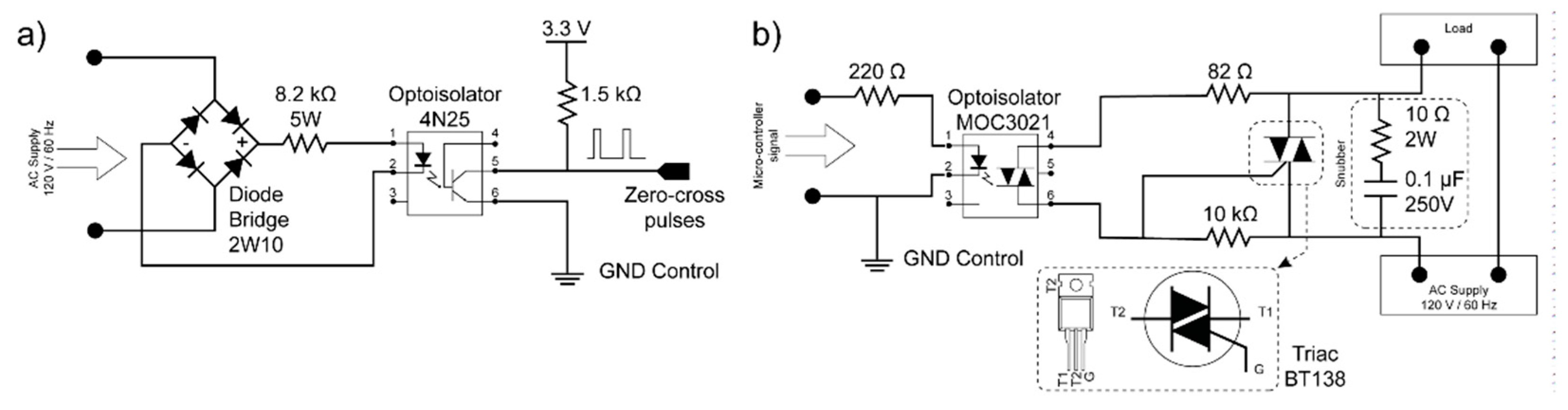
2.3.1. Zero-Crossing Detector Circuit

The sinusoidal signal of the AC supply allows the TRIAC to deactivate at each zero-crossing point as the current value drops below the holding current. Therefore, to ensure proper firing angle control, it is essential to determine the points where the zero crossings of the voltage signal corresponding to the AC supply occur. Figure 2a shows the schematic of the circuit implemented for the zero-crossing detector.

2.3.2. TRIAC Selection

In order to select a suitable model for the TRIAC, it is fundamental to consider the voltage and current values that the semiconductor must withstand in the on state (fully ON) and in the cut-off region (fully OFF). On state current that the TRIAC must handle corresponds to the maximum RMS value of 10 A, which is variable according to the load requirements. Also, the voltage that the device must withstand is the phase-neutral voltage of the AC supply, which has a maximum RMS value of 120 V; that is, the repetitive peak voltage that the TRIAC will handle results in a value of 169.71 V. According to the previously mentioned values, TRIAC to be used in the solid-state relay prototype is BT138 model. The main characteristics of the selected TRIAC can be shown in Table 1.

2.3.3. TRIAC Trigger Circuit

The circuit detailed in Figure 2b allows the TRIAC to be safely triggered using an optoisolator, which is activated through one of the microcontroller’s pins. Figure 2b shows the schematic of the circuit implemented for triggering the BT138 TRIAC. It is fundamental to mention that the TRIAC gate is excited with a phase control based on the activation of the system through the firing angle of the semiconductors. Control of the supply voltage is carried out by varying the firing angle of the thyristor gate. Alpha firing angle ( α ) is in a range between 0° and 180°. The implementation of the circuit for phase control turns out to be simple and reliable [21].

2.3.4. Snubber Network and Heat-Sink

The need for implementing a snubber network in the prototype arises from issues related to the unwanted triggering characteristics of the TRIAC, which occur when the load is significantly reactive, potentially exceeding the critical rate of change of the commutating voltage ( d V c o m / d t ) [22]. To solve this problem, the implementation of an RC snubber network between terminals MT1 and MT2 is required since this configuration limits abrupt voltage variations. The prototype requirements in terms of voltage and current levels are V O = 169.71   V , I = 10   A , and f s = 120   H z . In addition, we used the Quick Snubber Design proposed by Cornell Dubilier in [23]. The complete circuit of the controlled solid-state relay is shown in Figure 2b.
To enhance the protection of the controlled solid-state relay prototype, a heat sink is proposed to maintain the necessary thermal flow and prevent the semiconductor from reaching its melting point. For this purpose, it is essential to know the value of the TRIAC power dissipation, which is influenced by the load current and can be calculated using the equations from [24,25]. In this case, TRIAC power dissipation is P = 13.74   W . This is based on that value and other parameters, which are ambient temperature, junction temperature, and the thermal resistances of the system. In addition, we used a direct contact and the analysis of [24]; the junction-to-ambient thermal resistance is R t h j a = 5.53   ° C / W . Accordingly, the model of the heat sink is TEA40 [26], whose thermal resistance is 5.6   ° C / W .

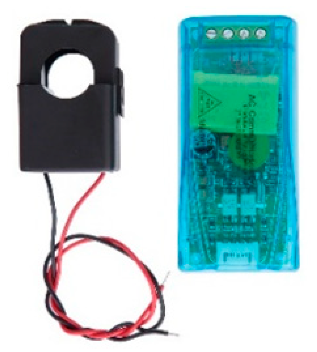
2.4. Power Measurement System

For selecting a power measurement system that focuses on acquiring voltage, current, and power factor data of the load, the requirements of the maximum RMS values 120 V @ 10 A were considered. So, a PZEM-004T V3.0 AC communication module (see Figure 3) is used, which measures AC voltage, current, active power, frequency, power factor, and the energy of the application to which it is connected. Data obtained are sent to a microcontroller through WIFI wireless communication, which presents the information in an Android application for system monitoring.

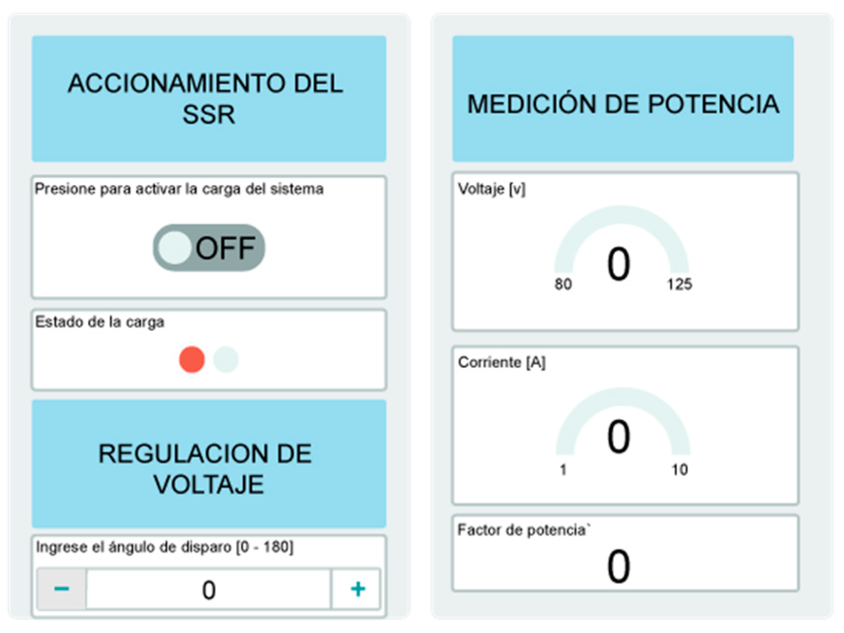
2.5. Android Application for Remote Driving and Monitoring of the Solid-State Relay Using WIFIi

To design the Android application, the Arduino Cloud interface was selected, as it supports developing projects with embedded systems through Wi-Fi connections. Among the compatible devices are ESP32 microcontrollers since these devices have an integrated WIFI module [28]. The configuration of ESP32 boards in Arduino Cloud is carried out using a device ID and a secret key. These tools, along with WIFI credentials, are ideal for connecting to the Arduino database. In this way, it is possible to generate the operation as well as remote monitoring of the prototype through a wireless network with an Internet connection. The Android application design is shown in Figure 4.

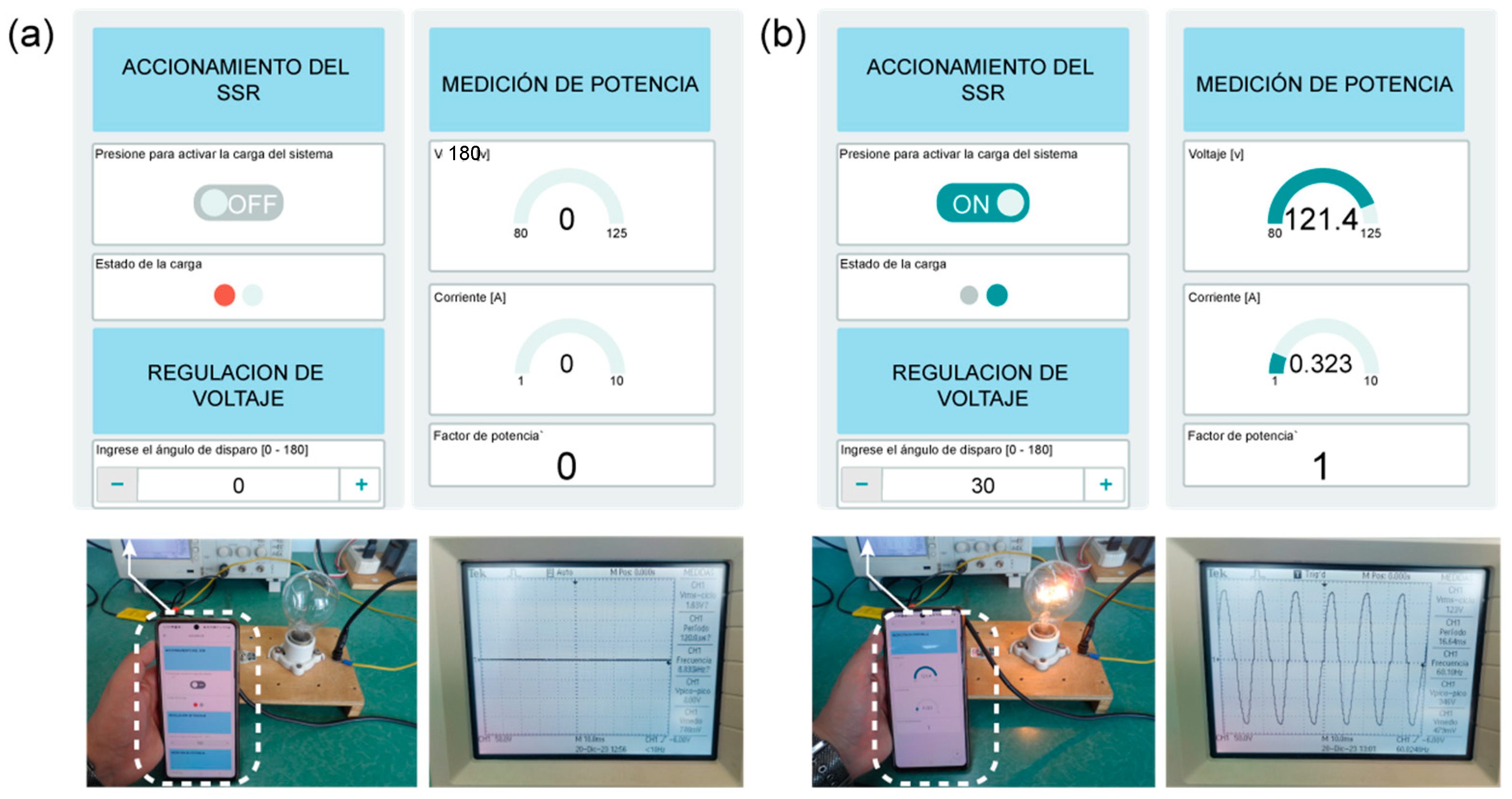
3. Results and Discussion

This section shows the operation of the prototype with different configurations of the system load, such as a resistive load (R) and a resistive–inductive load (RL). The results demonstrate the system’s ability to regulate the firing angle of the TRIAC and manage the load effectively.
For the prototype to function properly, it is important to consider that losses are generated during operation. These losses are caused by the elements within the SSR’s internal structure. For this case study, the main losses are found in the power semiconductor, which is a TRIAC BT138 with a value of 13.74 W, as well as in the resistance that is located after the diode bridge, that is, at the AC supply with a value of 0.82 W. These losses have a total estimated value of 14.56 W, which represents 1.21% of the maximum power that can be supplied to the load. This is considering that the maximum power is 1.2 kW when there is no phase lag between the voltage and the current.

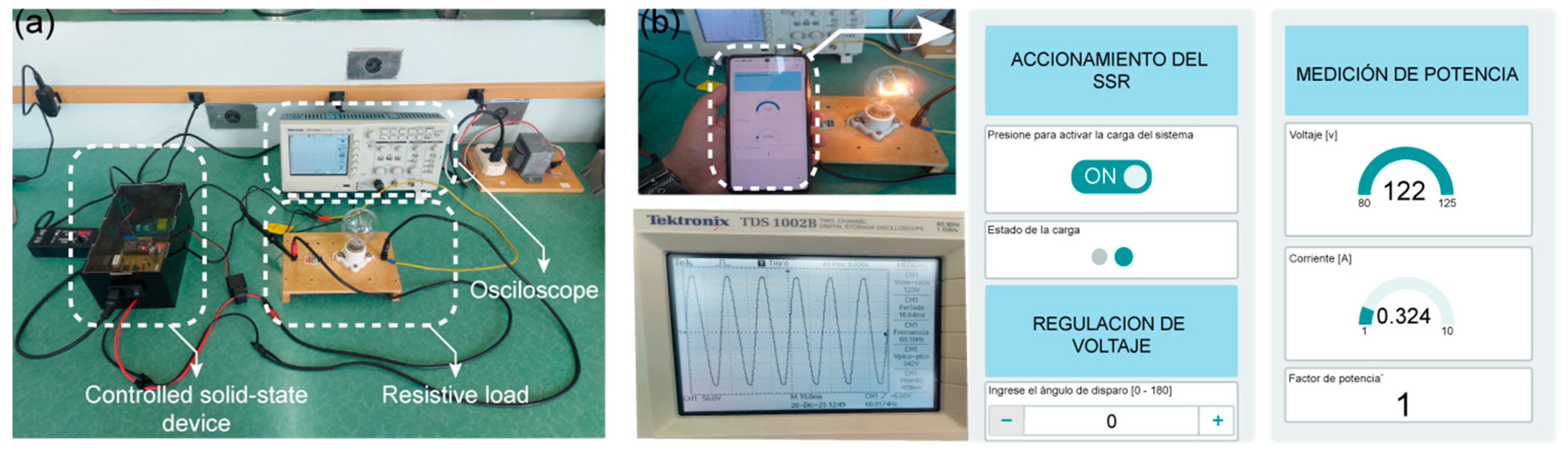
3.1. Resistive Load (R) Tests

To validate the prototype’s functionality, a 100 W incandescent light bulb was used as a resistive load. The firing angle (α) was regulated through the Android application, allowing control over the bulb’s illumination. It was possible to analyze and select the appropriate components to carry out the design and implementation of the power, control, measurement, and remote communication circuit of the system. By connecting the bulb as a load, the firing angle (α) can be regulated throughout its range, that is, from 0° to 180°, where 0 electrical degrees determines that the load is fully on, with the bulb receiving the complete mains voltage and displaying a full sine waveform. The trigger angle is regulated with the Android application, as shown in Figure 5a.
The results of the voltage, current, and power factor measurements using the PZEM-004T V3.0 module are shown in Figure 5b. On the other hand, at a firing angle of 180 electrical degrees, the load is off, as shown in Figure 6a, as the bulb does not receive any voltage and remains unlit. This demonstrates the system’s ability to completely control the load state through the firing angle adjustment.
For intermediate angles, such as 30°, the bulb’s illumination varies accordingly. Figure 6b shows the results at 30°, indicating precise control over the load’s voltage and power factor, monitored through the Android application.

3.2. Resistive–Inductive Load (RL) Test

In this test, a 250 mH inductor was added in series with the 100W incandescent bulb, creating a resistive–inductive load, as Figure 7a shows. Various firing angles were tested to observe the system’s response to the inductive component.
After connecting the inductor, several tests of the firing angle were conducted. For values less than 16 electrical degrees, the voltage regulation was affected. This is due to the inductive load, which generates a phase lag between the voltage and current. Consequently, the current conduction lasts for more than 180 electrical degrees, and the TRIAC deactivates every time the current drops to zero. In this way, the electrical current is extinguished at the β angle. Because an extinction angle exists, the critical firing angle ( α c ), can be defined as the limit value to go from continuous conduction mode to discontinuous conduction mode and vice versa. This parameter is very important to the operation of the prototype because it corresponds to the angle from which the AC control can be made. One may note from Figure 7b that the power factor no longer corresponds to 1, which is due to the presence of the inductor.

3.3. Prototype Tests and Theoretical Results Comparison

In order to verify the operation of the controlled solid-state relay, the following tables are shown below as a summary where the voltage, current, and power factor results obtained through the prototype and mathematical calculations are compared. Table 2 shows the measurements when there is a resistive load is used as the output of the system. The results are significantly similar for each of the firing angles. The main differences are because in the tests with the prototype, there are variations in the resistive value of the bulb, which changes as its temperature increases. The theoretical results were carried out using Equations (1)–(3), which are proposed in [29].
V r m s = V s 1 π π α + sin 2 α 2 1 / 2
I r m s = V r m s R = V s R 1 π π α + sin 2 α 2 1 / 2
p f = 1 π π α + sin 2 α 2
where V r m s is the RMS voltage across the load, V s is the mains voltage, α is the firing angle, R is the value of the bulb resistance, I r m s is the load RMS current, and p f is the load power factor. It is very important to consider that the approximate value of the bulb resistance is 370 Ω .
Similarly to the previous case, Table 3 shows the measurements obtained when the system has an RL load as output. Based on this information, continuous conduction is achieved for firing angles less than 16°. Likewise, the firing angle for testing the prototype cannot be less than the value mentioned above since the load voltage and current will be sinusoidal. The theoretical results were calculated using Equations (4)–(8), which are also proposed in [29].
  V r m s = V s 1 π β α + sin 2 α 2 sin 2 β 2 1 / 2
  I r m s = V s cos ϕ R θ π sin θ cos 2 α + θ + ϕ π cos ϕ 1 / 2
θ = β α
ϕ = tan 1 ω L R
p f = cos ϕ
where V r m s is the RMS voltage across the load, V s is the mains voltage, β is the extinction angle, α is the firing angle, ϕ is the impedance angle, θ is the driving angle, ω is the angular frequency, R is the value of the bulb resistance, L is the value of the inductor, I r m s is the load RMS current, and p f is the load power factor. It is very important to consider that the approximate value of the extinction angle is 196°.
As can be seen from the Table 4, while commercial SSRs are robust and reliable for specific applications, the developed SSR stands out by integrating IoT features (WIFI) for remote monitoring and control, which is particularly beneficial for smart home environments in domotic applications.

4. Conclusions

The design and construction of a controlled solid-state relay (SSR) with a variable duty ratio for domotic applications were successfully completed. This project demonstrated the feasibility of integrating IoT-based remote control and monitoring with a robust SSR design, providing enhanced functionality and reliability for smart home environments. Experimental results, as shown in Table 2 and Table 3, validate the system’s capability to regulate the firing angle for both resistive and resistive–inductive loads. The close alignment between experimental and theoretical results highlights the precision and reliability of the proposed method in controlling different load profiles.
The proposed system can be employed for automated control of household devices, efficient energy management, and real-time monitoring of electrical parameters, making it particularly useful for smart home setups that prioritize energy efficiency and automation. Additionally, the system’s ability to handle different load profiles, combined with features such as a network snubber and heatsink for enhanced durability, makes it a robust and adaptable solution for diverse domotic applications.
Furthermore, the comprehensive evaluation provided in this study shows that the SSR system not only supports seamless integration into smart home environments but also enhances the management of various electrical loads with high accuracy. Future work could explore its integration with renewable energy sources and the further optimization of control algorithms to improve system performance, extending its potential applications in both residential and industrial smart grid environments.

Author Contributions

Conceptualization, K.B. and J.M.; methodology, K.B., J.M. and W.C.; software, K.B., J.M. and J.R.; validation, K.B., W.C., J.M. and J.R.; formal analysis, J.M. and K.B.; investigation, K.B., J.M., W.C. and J.R.; resources, K.B.; data curation, W.C.; writing—original draft preparation, K.B.; writing—review and editing, J.M.; visualization, W.C.; supervision, J.M. and J.R. All authors have read and agreed to the published version of the manuscript.

Funding

This research received no external funding.

Institutional Review Board Statement

Not applicable.

Informed Consent Statement

Not applicable.

Data Availability Statement

Data are contained within the article.

Conflicts of Interest

The authors declare no conflicts of interest.

References

  1. Revista ElectroIndustria. ¿Qué es un Relé de Estado Sólido? 2020. Available online: https://www.emb.cl/electroindustria/articulo.mvc?xid=3691&ni=que-es-un-rele-de-estado-solido# (accessed on 18 July 2023).
  2. GEYA. Aplicaciones y Usos de Relés de Estado Sólido. 2022. Available online: https://www.geya.net/es/8-solid-state-relay-applications-and-uses/#:~:text=Los%20rel%C3%A9s%20de%20estado%20s%C3%B3lido%20se%20utilizan%20ampliamente%20en%20los,se%20pueden%20utilizar%20otros%20dispositivos (accessed on 18 July 2023).
  3. Cerem Comunicación. Por qué el Internet de las Cosas (iot) Promete Cambiar la Vida del ser Humano. 2022. Available online: https://www.cerem.es/blog/porque-el-internet-de-las-cosas-iot-promete-cambiar-la-vida-del-ser-humano#:~:text=Con%20IoT%20se%20puede%20programar,las%20personas%20a%20nivel%20mundial (accessed on 18 July 2023).
  4. Shaw, K. ¿Qué es el Wi-Fi y Por Qué es tan Importante? 2020. Available online: https://concepto.de/wifi/#:~:text=El%20wifi%20da%20acceso%20a%20Internet%20a%20lo,o%20en%20cada%20piso%20de%20un%20edificio%20peque%C3%B1o. (accessed on 18 July 2023).
  5. International Journal of Engineering and Advanced Technology (IJEAT). IoT Based Relay Operation. 2019. Available online: https://www.ijeat.org/wp-content/uploads/papers/v9i1/A1415109119.pdf (accessed on 29 July 2024). [CrossRef]
  6. Miletiev, R.; Yordanov, R. Compact smart solid-state relay with WiFi connectivity. In Proceedings of the 2022 International Conference on Emerging Trends in Engineering, Technology, and Science (ETETSS), Sozopol, Bulgaria, 13–15 September 2022; pp. 67–72. [Google Scholar] [CrossRef]
  7. Risteska Stojkoska, B.L.; Trivodaliev, K.V. A review of Internet of Things for smart home: Challenges and solutions. J. Clean. Prod. 2017, 140, 1454–1464. [Google Scholar] [CrossRef]
  8. Mocrii, D.; Chen, Y.; Musilek, P. IoT-based smart homes: A review of system architecture, software, communications, privacy, and security. Internet Things 2018, 1–2, 81–98. [Google Scholar] [CrossRef]
  9. Alaa, M.; Zaidan, A.A.; Zaidan, B.B.; Talal, M.; Kiah, M.L.M. A review of smart home applications based on Internet of Things. J. Netw. Comput. Appl. 2017, 97, 48–65. [Google Scholar] [CrossRef]
  10. Budiyanto, S.; Silalahi, L.M.; Silaban, F.A.; Salamah, K.S.; Rahayu, F.; Wahyuddin, M.I.; Andryana, S. Design of control and monitoring tools for electricity use loads, and home security systems with internet of things system based on Arduino Mega 2560. IOP Conf. Ser. Mater. Sci. Eng. 2020, 909, 012020. [Google Scholar] [CrossRef]
  11. Fernández, M.; Perpiñà, X.; Rebollo, J.; Vellvehi, M.; Sánchez, D.; Cabeza, T.; Llorente, S.; Jordà, X. Solid-State Relay Solutions for Induction Cooking Applications Based on Advanced Power Semiconductor Devices. IEEE Trans. Ind. Electron. 2019, 66, 1832–1841. [Google Scholar] [CrossRef]
  12. Abduraimov, E.; Khalma, D. Development of contactless solid state voltage relay. In Proceedings of the 2020 RSES International Conference, Kazan, Russia, 21–26 September 2020. [Google Scholar] [CrossRef]
  13. Mu, J.; Wang, L. Research on main circuit topology for a novel DC solid-state circuit breaker. In Proceedings of the IEEE Conference on Industrial Electronics and Applications, Taichung, Taiwan; 2010; pp. 926–930. [Google Scholar] [CrossRef]
  14. OMEGA. Relés de Estado Sólido. 2021. Available online: https://es.omega.com/temperature/pdf/SSRL240_660.pdf (accessed on 19 September 2023).
  15. Crydom SSR Ltd. Output Switching Functions of Solid-State Relays. 2011. Available online: https://pim.galco.com/Manufacturer/Crydom/TechDocument/Application%20Note/ssr_switching_functions_app3.pdf (accessed on 19 September 2023).
  16. Barkana, A.; Cook, G.; McVey, E.S. A Solid-State Relay. IEEE Trans. Ind. Gen. Appl. 1973, IGA-9, 589–594. [Google Scholar] [CrossRef]
  17. Schweber, B. Cómo Regular la Corriente o el Voltaje de Forma Segura y Eficiente con los SSR. DigiKEY, 26 February 2019. Available online: https://www.digikey.com/es/articles/how-to-safely-and-efficiently-switch-current-or-voltage-using-ssrs (accessed on 19 September 2023).
  18. Venugopal, K.B.; Srivani, S.G. Design and Analysis of MOSFET’s as Solid-State Relays for Precise AC Load Control. In Proceedings of the 2023 International Conference on Smart Technologies in Computing, Electrical and Electronics (CSITSS), Bangalore, India, 2–4 November 2023. [Google Scholar] [CrossRef]
  19. Fernández, M.; Perpiñá, X.; Vellvehi, M.; Jordà, X.; Cabeza, T.; Llorente, S. Analysis of solid state relay solutions based on different semiconductor technologies. In Proceedings of the 2017 19th European Conference on Power Electronics and Applications (EPE’17 ECCE Europe), Warsaw, Poland, 11–14 September 2017. [Google Scholar] [CrossRef]
  20. Philips Semiconductors. Triacs BT138 Series. 1997. Available online: https://pdf1.alldatasheet.com/datasheet-pdf/view/16781/PHILIPS/BT138.html (accessed on 21 November 2023).
  21. Valle, C. Diseño, Simulación y Control de Temperatura de un Horno Eléctrico Empleando Resistencias—Control Electrónico al Lado AC. Bachelor’s Thesis, Escuela Politécnica Nacional, Quito, Ecuador, 2022. [Google Scholar]
  22. González, M. Dispositivos Semiconductores de Potencia. 2015. Available online: http://orga.blog.unq.edu.ar/wp-content/uploads/sites/71/2015/06/Dispositivos-de-potencia.pdf (accessed on 30 September 2023).
  23. Cornell Dubilier. Application Guide Snubber Capacitors. Available online: https://www.cde.com/resources/technical-papers/igbtAPPguide.pdf (accessed on 13 November 2023).
  24. Philips Semiconductors. AN10384 Triacs: How to Calculate Power and Predict Tjmax. 2005. Available online: https://www.farnell.com/datasheets/1760767.pdf (accessed on 22 November 2023).
  25. Dillon, E.; Palma, P. Diseño de Un Sistema Automático de Regulación de Voltaje y Frecuencia Generados por una Micro-Central Hidro-Eléctrica. Bachelor’s Thesis, Escuela Politécnica Nacional, Quito, Ecuador, 2014. [Google Scholar]
  26. DISIPA. Catálogo General 3.0. 2019. Available online: https://disipa.net/catalogos-1 (accessed on 14 November 2023).
  27. Peacefair Electronic Technology. PZEM-004T V3.0 User Manual. Available online: https://innovatorsguru.com/wp-content/uploads/2019/06/PZEM-004T-V3.0-Datasheet-User-Manual.pdf (accessed on 24 November 2023).
  28. Espressif Systems. ESP32 ESP-IDF Programming Guide. 2023. Available online: https://docs.espressif.com/projects/esp-idf/en/latest/esp32/esp-idf-en-master-esp32.pdf (accessed on 26 November 2023).
  29. Rashid, M.H. Electrónica de Potencia: Circuitos, Dispositivos y Aplicaciones, 2nd ed.; Prentice Hall Hispanoamericana: Naucalpan de Juárez, Mexico, 1995. [Google Scholar]
  30. OMRON. Technical Explanation for Solid-state Relays. Available online: https://www.ia.omron.com/data_pdf/guide/18/ssr_tg_e_9_2.pdf (accessed on 14 October 2024).
  31. INFINEON. From Electromechanical Relays to Robust Semiconductor Solutions: Solid-State Relays with Optimized Superjunction FET Technology. Available online: https://www.infineon.com/dgdl/Infineon-Solid-state_relays_with_optimized_SJ_FET_technology-Whitepaper-v01_00-EN.pdf?fileId=8ac78c8c7bb971ed017bbaf30d3c02af&da=t (accessed on 14 October 2024).
  32. SHARP. “S108T02 Series”. Available online: https://files.seeedstudio.com/wiki/Grove-Solid_State_Relay/res/S208t02_datasheet.pdf (accessed on 14 October 2024).
Figure 1. SSR internal structure [17].
Engproc 77 00014 g001
Figure 2. Implemented circuits: (a) zero-crossing detector, (b) controlled triggering.
Engproc 77 00014 g002
Figure 3. PZEM-004T V3.0 AC module [27].
Engproc 77 00014 g003
Figure 4. Arduino Cloud interface.
Engproc 77 00014 g004
Figure 5. Experiment setup: (a) setup for resistive load, (b) measurements at 0 degrees.
Engproc 77 00014 g005
Figure 6. Experiments at different shooting angles: (a) 180 degrees, (b) 30 degrees.
Engproc 77 00014 g006
Figure 7. Experiment setup: (a) setup for rL load, (b) operation at 16 degrees.
Engproc 77 00014 g007
Table 1. Main parameters of TRIAC BT138 [20].
ParameterSymbolValue
Repetitive peak off-state voltage V D R M 600 V
RMS on-state current I T ( R M S ) 12 A
Gate trigger voltage V G T 1.5 V
Operating junction temperature T J 125 °C
Thermal resistance junction to mounting base R θ j c 1.5 K/W
Table 2. Results with a resistive load.
Firing Angle
( α )
Prototype ResultsTheoretical ResultsPercentage Errors
Voltage [V]Current [A]Power FactorVoltage [V]Current [A]Power FactorVoltageCurrentPower Factor
1220.32411200.32411.6700
30°121.40.3231118.260.320.992.660.941.01
50°115.90.1561115.50.1520.940.352.636.38
70°103.80.1420.98101.360.1370.852.413.6515.29
180°000000---
Table 3. Results with a resistive–inductive load.
Firing Angle
( α )
Prototype ResultsTheoretical ResultsPercentage Errors
Voltage [V]Current [A]Power FactorVoltage [V]Current [A]Power FactorVoltageCurrentPower Factor
16°122.60.3120.971200.3160.972.171.270
25°119.40.3090.971170.3060.972.050.980
70°105.90.2750.95100.420.2630.975.464.562.06
80°98.50.2660.9396.290.2520.972.35.564.12
Table 4. Comparison with other SSR options.
DeviceMax CurrentMax VoltageControl TypeSnubberRemote ControlDatasheet Reference
Developed SSR10 A120 VTRIACYesWIFIi---
Omron G3ZA Series 10 A240 VTRIACYesNo[30]
Infineon FET SSR5 A600 VFETNoNo[31]
Seeed Studio S108T02 Series8 A600 VTRIACYesNo[32]
Disclaimer/Publisher’s Note: The statements, opinions and data contained in all publications are solely those of the individual author(s) and contributor(s) and not of MDPI and/or the editor(s). MDPI and/or the editor(s) disclaim responsibility for any injury to people or property resulting from any ideas, methods, instructions or products referred to in the content.

