Abstract
Unlike polymers and metals, additive manufacturing (AM) of ceramic parts has only recently become an increasingly important technology, thanks to ceramic’s exceptional thermal and chemical properties. Most of the AM-processed ceramic parts must undergo a sintering process that adds additional challenges. Managing post-sintering shrinkage remains a critical challenge that impacts the dimensional accuracy and integrity of the final printed components. This is particularly important for intricate designs if the part has triply periodic minimal surface lattice structures. This study systematically analyzes the effect of lattice parameters, namely cell sizes along the X, Y, and Z axes, lattice type, and wall thickness on the post-sintering shrinkage. A number of samples with different lattice parameters were designed and printed with an LCD 3D resin printer using commercially available aluminosilicate resin. Later, the specimens were subjected to the same sintering process, and the dimensions of the green bodies and sintered parts were studied to measure volumetric and linear shrinkages.
1. Introduction
Since the turn of the millennium, Additive Manufacturing (AM) has moved from using basic thermoplastics by a fused deposition modelling to using esoteric materials such as gallium-based liquid metals [1], directly printing soft stretchable soft robotic grippers [2] to directly 3D printing using pure copper [3]. In recent years, AM of ceramic components has emerged as a groundbreaking technology due to ceramics’ unique thermal and chemical properties. Unlike polymer and metal, AM application to create ceramic parts is more complicated. The very high melting temperature and very low ductility make processing difficult, and the poor thermal shock resistance usually results in crack formation if temperature treatment (sintering) is not well calibrated and controlled. Hence, additive manufacturing of ceramics is usually achieved by powder bed fusion or vat photopolymerization. Vat photopolymerization has become very popular recently due to many manufacturers releasing cheap Stereolithography (SLA) and Digital Light Processing (DLP/LCD)-based printers. Now, ceramic parts can be relatively cheaply made using ceramic powder suspended in photopolymers. In this process, a green body is first created using AM. Then, it is put through a debinding procedure where the photopolymer is burned off, leaving a “brown body” composed of ceramic particles. Then, the brown body is sintered and post-processed to achieve the desired dimensions within tolerance [4]. During this process, the first challenge comes from this photopolymer-based approach. The resin undergoes a light cross-linking and changes from a liquid to a solid, resulting in shrinkage and internal stresses, which may cause cracking during the debinding and sintering process. The parts also undergo another instance of shrinkage during these steps, and the resin burns off [5]. Furthermore, debinding thick-shelled green bodies poses another challenge as the thick walls are prone to cracking due to the gasses generated while the resin burns off, creating pressure inside the shells. Using infill structures and keeping the shell thickness to a minimum alleviates this issue, as the gasses and heated air can escape the thin porous structure without cracking [6]. Triply Periodic Minimal Surface (TPMS) lattices have been gaining research interest recently due to their self-support characteristic due to their periodic smooth surfaces and zero mean curvature [7]. The intricate nature of these designs adds to the difficulty of managing post-sintering shrinkage. This complexity necessitates a thorough understanding of the relationship between lattice parameters and the resulting shrinkage behavior. The final dimensions of sintered ceramic lattice structures are influenced by lattice parameters, such as cell sizes along the X, Y, and Z axes, and lattice type and thickness.
In this context, we systematically investigate the effects of lattice parameters on post-sintering shrinkage in ceramic lattice structures printed with a Liquid Crystal Display (LCD) 3D resin printer. The use of commercially available aluminosilicate resin adds practical value to our research. We hope to determine the nuanced effects of cell sizes and lattice types on volumetric and linear shrinkages during the post-sintering process by designing and printing samples with different lattice parameters.
2. Methodology
2.1. Lattice Generation
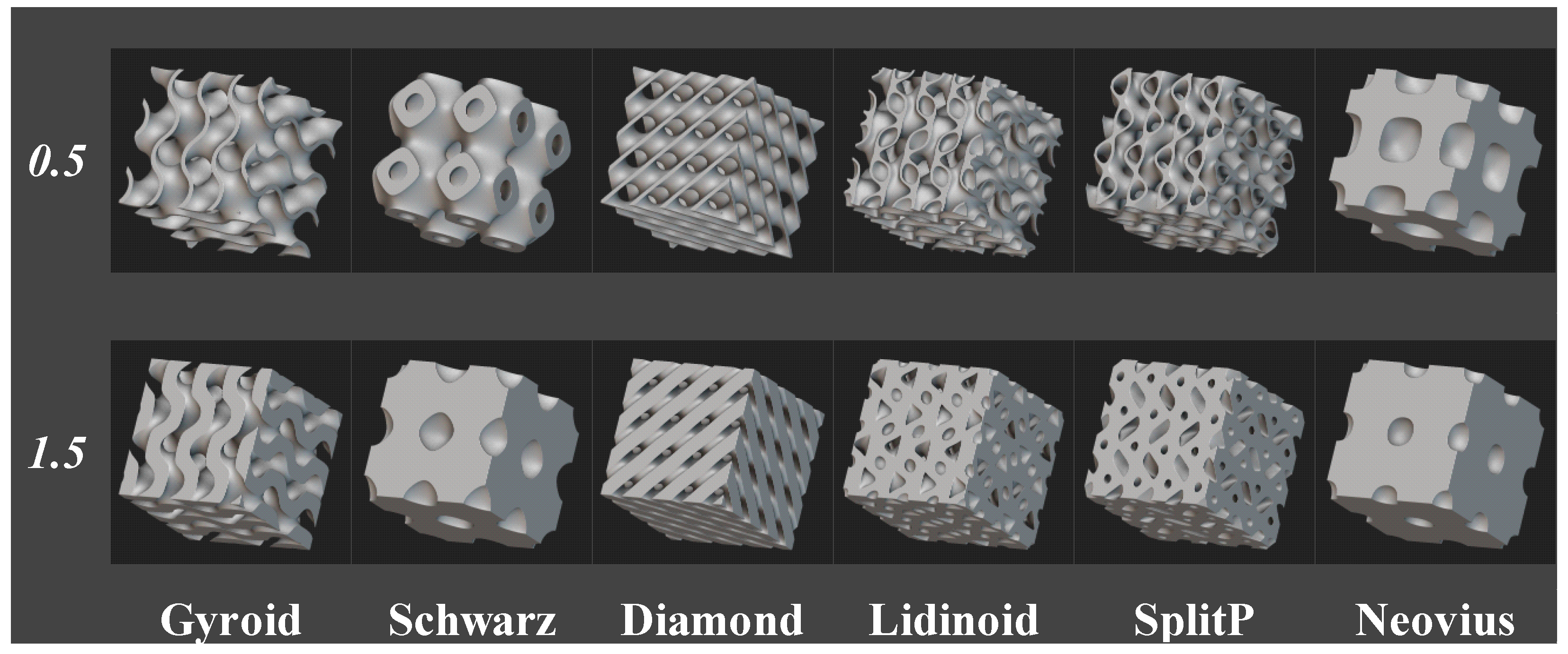
nTop software (version 4.8) [8] was used to generate the lattices. Using the software, a 10 mm3 cube was created and shelled out with TPMS lattices. Although numerous types of TPMS lattices are available [9], six types of TPMS lattices were created in both 0.5 mm and 1.5 mm shell thickness for this study, as they are readily available to model in the nTop. The lattice types are Gyroid, Schwarz, Diamond, Lidinoid, SplitP, and Neovius. In all cases, the unit cell size of the lattices was set to 5 for the x, y, and z directions. In Figure 1, We can see the array of lattices used in this study.
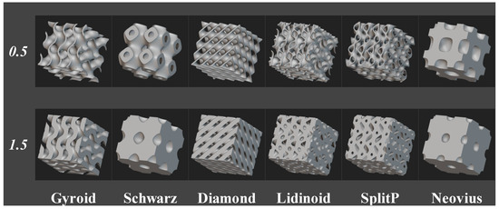
Figure 1.
Cad Models of the 6 Types of TPMS lattice and the two shell thicknesses used in this study.
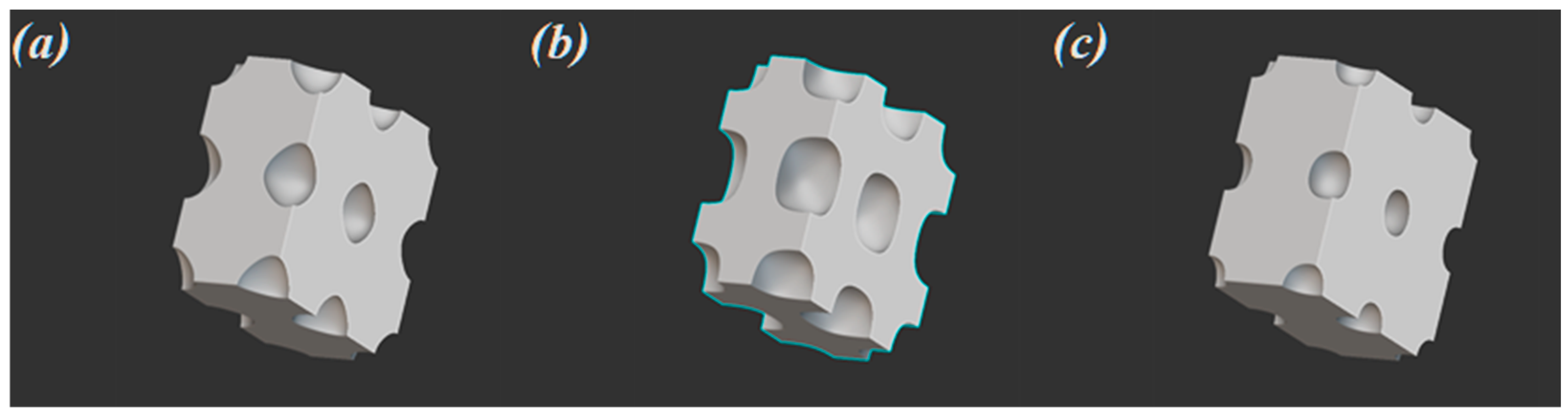
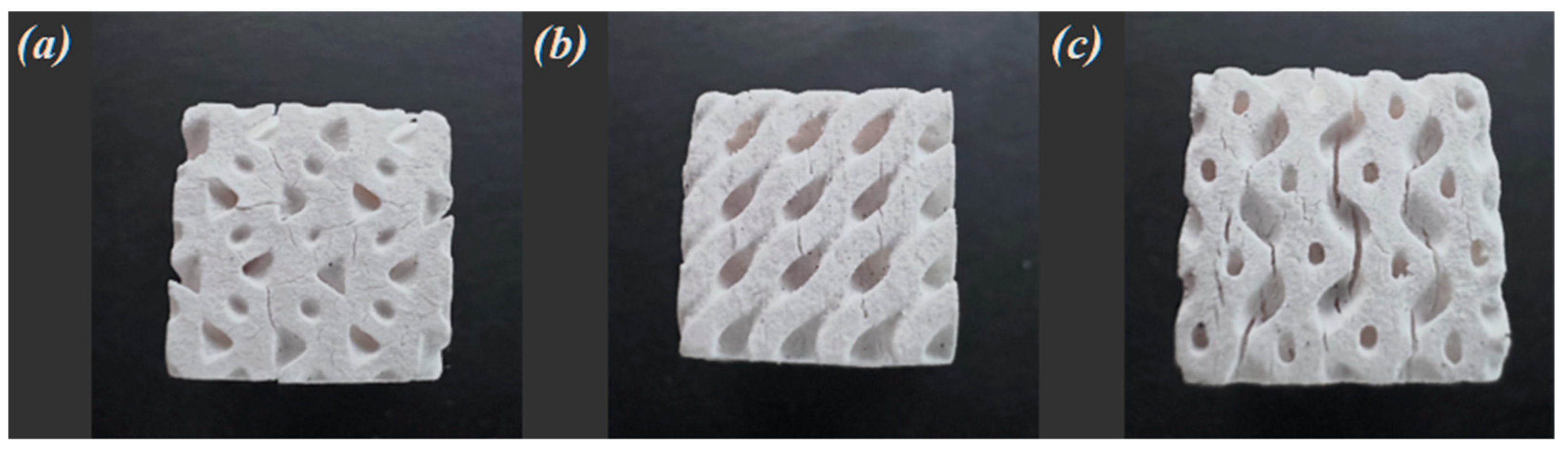
Of these lattices, the Neovius type of both 0.5 mm and 1.5 mm thickness and the Schwarz of 1.5 mm shell thickness was removed from the study, as they do not reduce the volume of the cube significantly to provide any advantage in practical applications; moreover, as they have discontinuous cavities inside the lattices, they will create a suction cup effect while printing and then trap uncured resins inside. These cavities can be seen in Figure 2.
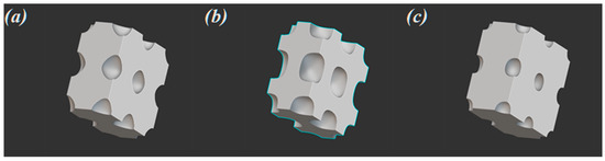
Figure 2.
Cross section to show discontinuous cavities inside (a) Schwarz with 1.5 mm shell thickness, (b) Neovius with 0.5 mm shell thickness, (c) Neovius with 1.5 mm shell thickness.
2.2. Print Parameters
An Elegoo Mars 3 Pro LCD 3D printer was used to print the lattices. The printer in question is a model manufactured by Elegoo, Shenzen, China [10]. This printer has a build volume of 143 × 89.6 × 175 mm3, an xy resolution of 0.035 mm, and it can print with a layer thickness of 0.01–0.02 mm [11]. To slice the cad file, a “Chitubox” slicer from Chitu Systems, Shenzhen, China [12] was used. Table 1 shows the parameters used for the print.

Table 1.
Parameters used in Chitubox to print the lattices on an Elegoo Mars 3 pro using Porcelite Ceramic Resin.
Porcelite UV-curable ceramic resin made by Tethon 3d, Omaha, NE, USA, was selected to print the lattices for this study [13]. This resin was designed to be used in a large variety of vat photopolymerization-based resin printers utilizing UV wavelengths between 350 and 405 nm. After the print finished, the green bodies were weighed and measured in the x, y, and z axis.
2.3. Debinding and Sintering
To facilitate debinding and sintering, we used a Vulcan 3-550 muffle furnace manufactured by Degussa-Ney Dental, Inc., Bloomfield, NJ, USA. This model of muffle furnace is capable of heating with a ramp temperature of 0.1 degree Celsius (°C) per minute. This slow ramp is essential to the debinding process of a ceramic resin-printed green body as it ensures the slow release of the gasses caused by the combustion of photopolymers inside the shell of the green body. The parts were first heated to 150 °C at 0.8 °C per minute and held at that temperature for 1 h, and then it was slowly ramped up from 0.1 °C per minute to 600 degrees °C. By this time, all the photopolymers were burned off. After a short hold period of 10 min, the ceramic green bodies are sintered to 1100 °C with a fast ramp of 3.3 °C per minute. Then, the furnace was turned off, and the parts were left to cool naturally. Table 2 shows the sintering temperature vs time table in hours. Figure 3 shows the resultant finished lattices.
Table 2.
Sintering curve.
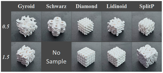
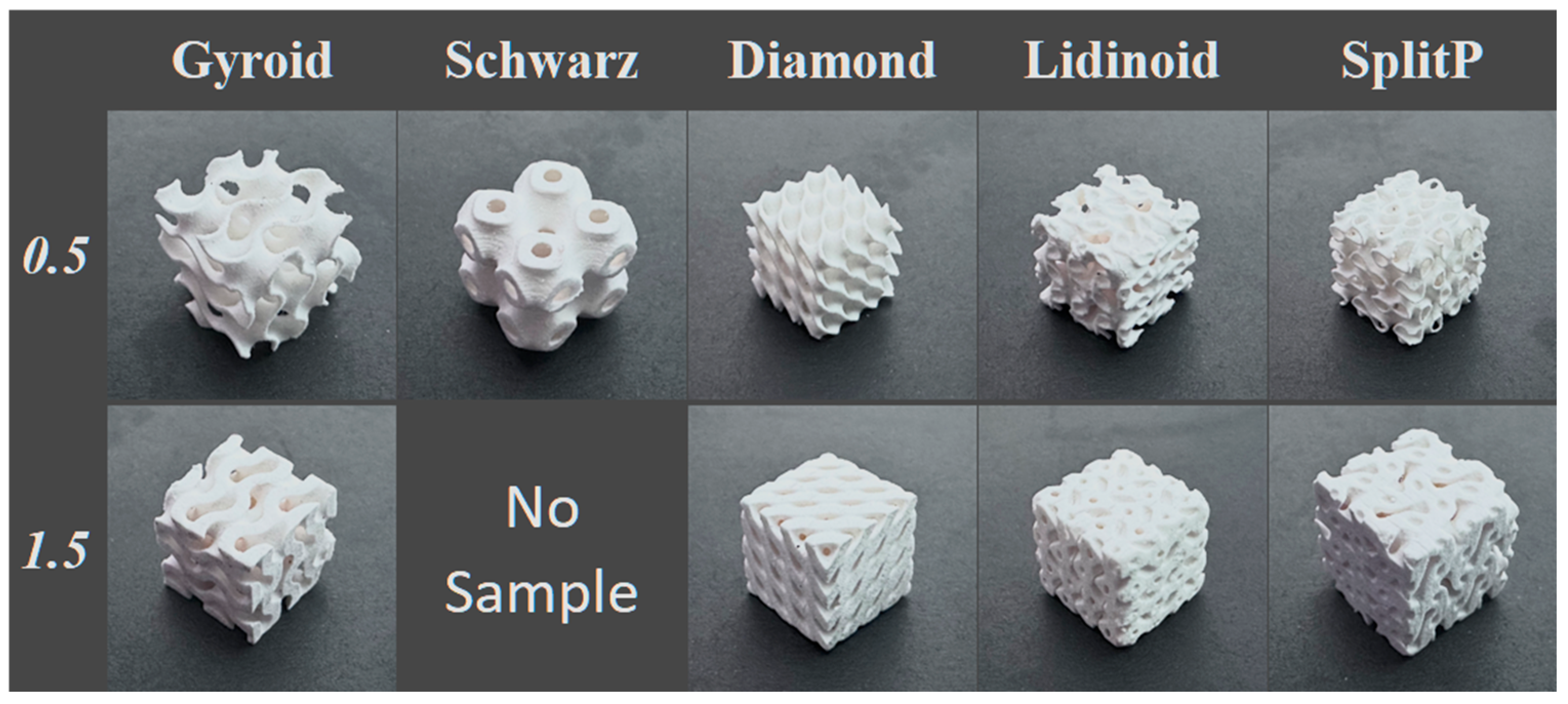
Figure 3.
Printed 10 × 10 × 10 ceramic lattices with 0.5 and 1.5 mm shell thickness after debinding and sintering.
After sintering, the resultant lattices were weighed and measured again to find how much linear and volumetric shrinkage resulted from the debinding and sintering process.
3. Discussion
Data were collected from nTop and by measuring the green bodies before debinding, sintering, and after. The volume fraction denotes how little material each type of lattice contains from a dense cube. Table 3 lists all the data from nTop and the calculated volume fraction against a cube with a volume of 1000 mm3.
Table 3.
Volume fraction calculated for all the lattice types from nTop.
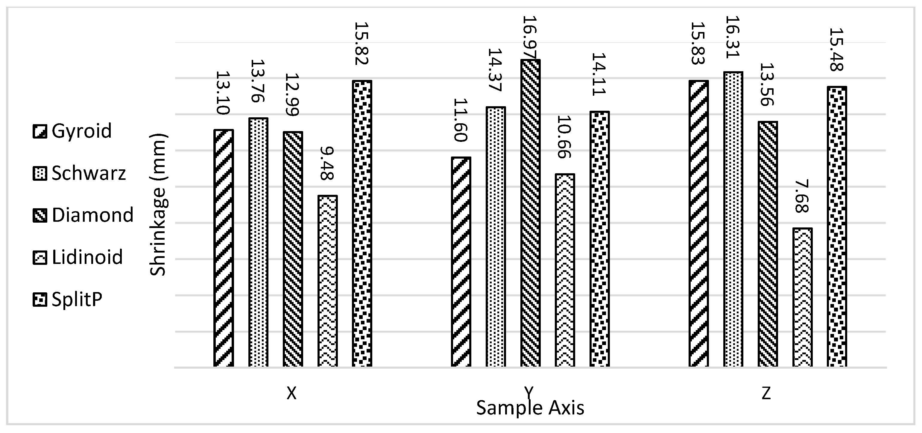
We can see that a Schwarz and Neovius with a 1.5 mm shell thickness has 84.39% and 91.86% volume of a solid cube. In order to calculate the linear shrinkage, we subtract post-sintering dimensions from pre-sintering dimensions, and express it as a percentage of the pre-sintering dimension in the x, y, and z axis. We can see in Figure 4 that for 0.5 mm shell thickness, the Lidinoid type lattice structure had the least amount of shrinkage compared to the other types. Other lattices have shrinkages ranging from 11% to 16.97%.
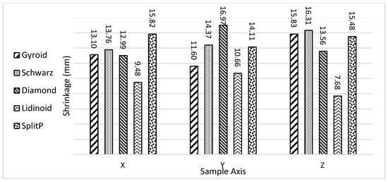
Figure 4.
Post-sintering shrinkage in percentage for 0.5 mm shell thickness for each type of lattice.
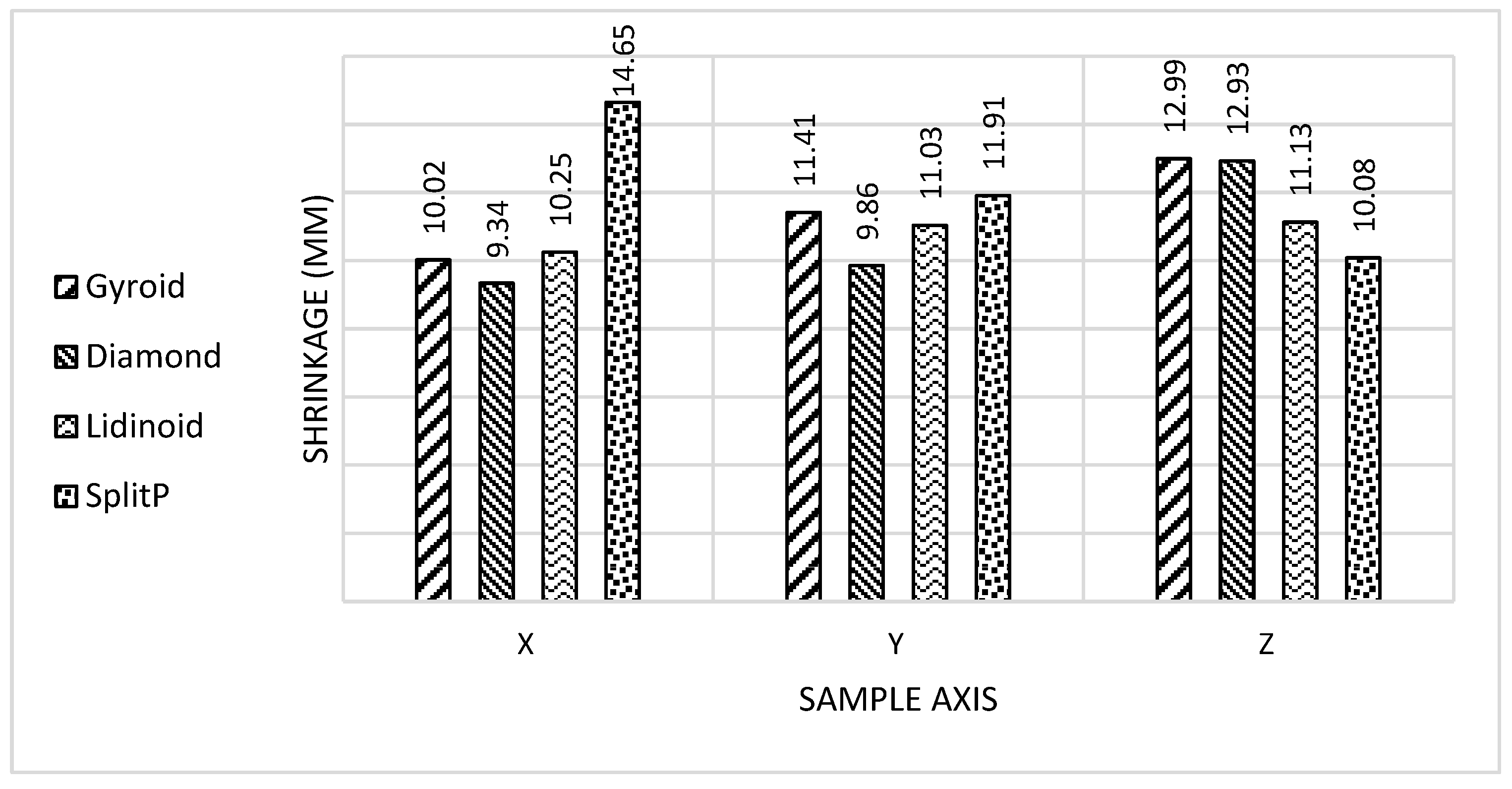
Figure 5 shows the same information for the lattices with a shell thickness of 1.5 mm. Here, we can see a trend different from what we saw for the 0.5 mm lattices.

Figure 5.
Post-sintering shrinkage in percentage for 1.5 mm shell thickness for each type of lattice.
We can see that, other than the x axis of the SplitP lattices, all other axes for the remaining lattice types show lower shrinkage percentages. As the resin, print parameter, and the debinding and sintering procedures were the same for all the samples, all samples were expected to show similar levels of shrinkage, yet here we can see the trend is not being followed. The answer lies in the samples. In Figure 6, we can see that for the 1.5 mm shell thickness samples for Diamond, SplitP, and Lidinoid types of lattices, cracks propagated from the entire section of the samples.
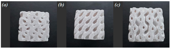
Figure 6.
Cracks on (a) Lidinoid, (b) Diamond, (c) SplitP types of lattices with 1.5 mm shell thickness.
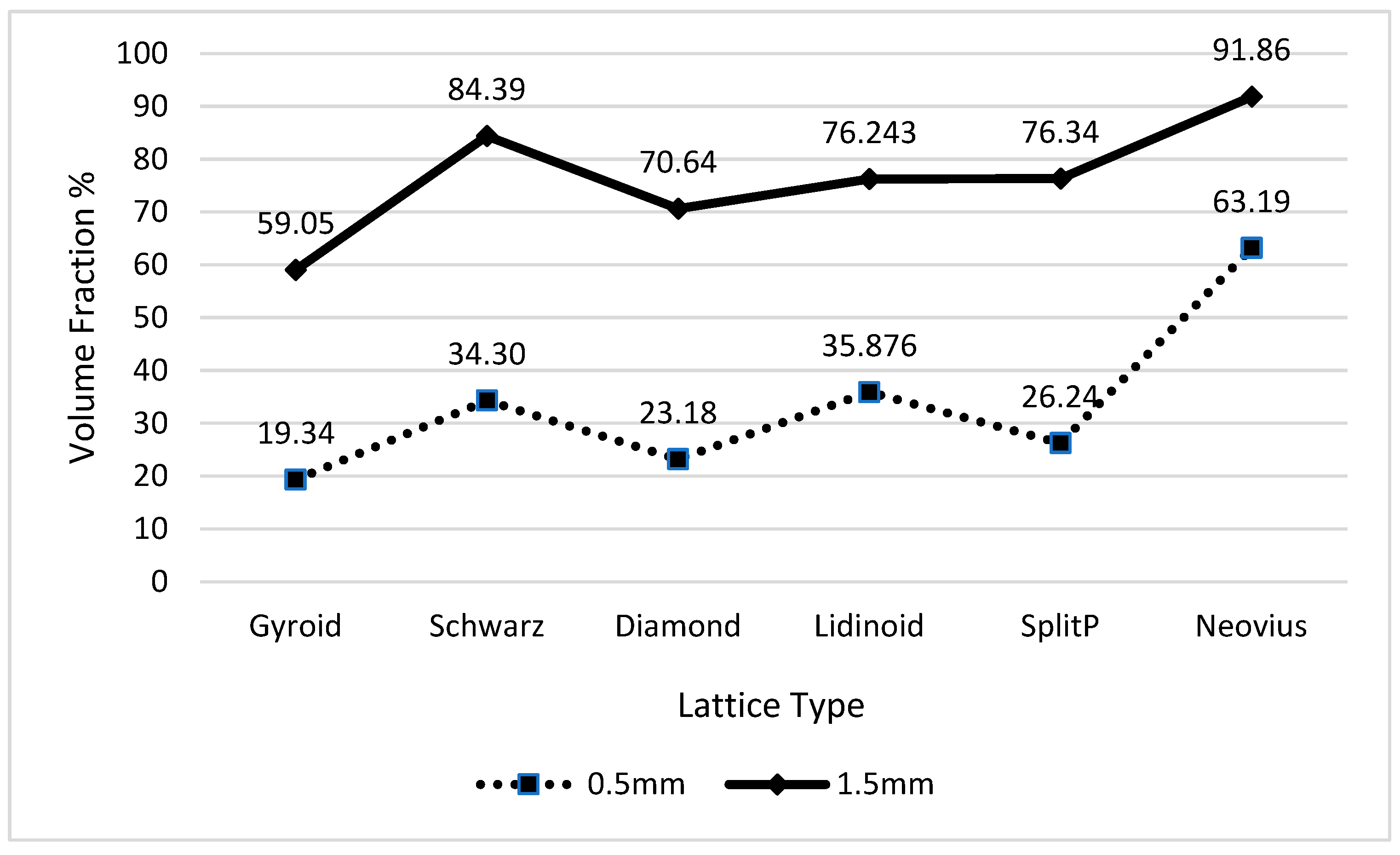
We can correlate these cracks with the volume fraction of the samples. Data from Table 2 is plotted in Figure 7. We can see that lattices with a volume fraction over 60 have exhibited cracking even with a very slow temperature ramp used during the debinding process. The gyroid lattice with a volume fraction of 59.05 printed and sintered well without any crack, whereas all the other samples over 60 have multiple cracks in all axes.
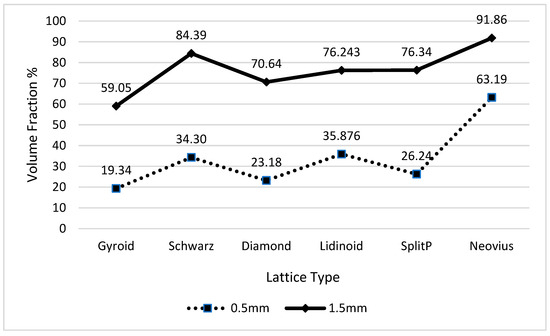
Figure 7.
Table of volume fraction for samples with 0.5 mm and 1.5 mm lattice shell thickness.
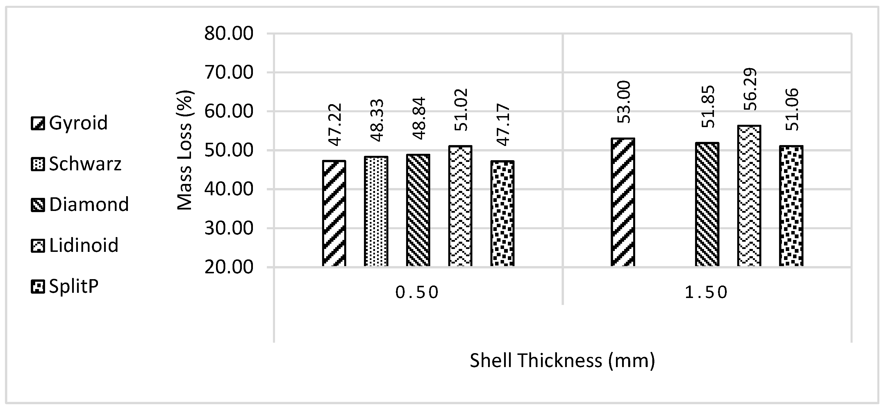
Finally, in Figure 8, we can see the shrinkage in terms of mass. As the photopolymers combust and leave the green body, they leave empty pores in the sample. The mass of the samples lost during the debinding process depends on the composition of the photopolymer resin component. As the same resin and post-processing procedure was followed for all the samples, the result is expected to be within 10% of each other, which is true for this case.
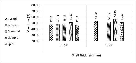
Figure 8.
Mass shrinkage after debinding and sintering.
4. Conclusions
In conclusion, our study investigated post-sintering shrinkage in ceramic lattice structures produced through LCD 3D resin printing. Our first finding is that by varying shell thickness, we can obtain continuous or discontinuous cavities, depending on the lattice type. The discontinuous cavities cause a severe issue when using any kind of vat polymerization-based AM techniques as they trap liquid resin, which cannot be drained easily, causing print failures and other issues. However, these lattices can be used to create closed-cell bodies to make compressible structures. We have identified some interesting insights about the relationship between volume fractions of ceramic resin-based prints and post-processing-induced cracks. We found that lattice structures with volume fractions exceeding 60% were prone to cracking during post-processing, specifically during debinding and impacting expected shrinkage. Thicker lattice shell thicknesses correlated with increased crack occurrence and deviations in shrinkage percentages as they increase volume fraction significantly depending on lattice type. Considering both dimensional changes and structural integrity is crucial in the design and fabrication of ceramic parts. Implementing infill structures and minimizing shell thickness can mitigate internal stresses and crack formation challenges. We were limited to one sample of each type and shell thickness due to a lack of materials; in the future, we intend to perform this study again utilizing other formulations of ceramic resin and multiple samples of each type of lattice and shell thickness.
Overall, our findings contribute to optimizing ceramic additive manufacturing, enhancing dimensional accuracy and mechanical resilience in various industrial applications.
Author Contributions
Conceptualization, M.R.A. and M.A.H.K.; Methodology, M.R.A.; Software, M.R.A.; Validation, M.R.A.; Formal Analysis, M.R.A.; Investigation, M.R.A.; Re-sources, M.A.H.K.; Data Curation, M.R.A.; Writing—Original Draft Preparation, M.R.A.; Writing—Review & Editing, M.R.A. and M.A.H.K.; Visualization, M.R.A.; Supervision, M.A.H.K. and M.R.A.; Project Administration, M.A.H.K.; Funding Acquisition, M.A.H.K. All authors have read and agreed to the published version of the manuscript.
Funding
This research received no external funding.
Institutional Review Board Statement
Not applicable.
Informed Consent Statement
Not applicable.
Data Availability Statement
The data presented in this study are available in the manuscript. For further inquiries, please contact the corresponding author (mohammad.khondoker@uregina.ca).
Acknowledgments
The authors acknowledge Robert Jones, and the Process Systems Lab at the University of Regina for their invaluable assistance during this study.
Conflicts of Interest
The authors declare no conflict of interest.
References
- Khondoker, M.A.H.; Sameoto, D. Fabrication methods and applications of microstructured gallium based liquid metal alloys. Smart Mater. Struct. 2016, 25, 093001. [Google Scholar] [CrossRef]
- Khondoker, M.A.H.; Baheri, N.; Sameoto, D. Tendon-Driven Functionally Gradient Soft Robotic Gripper 3D Printed with Intermixed Extrudate of Hard and Soft Thermoplastics. 3D Print. Addit. Manuf. 2019, 6, 191–203. [Google Scholar] [CrossRef]
- Sakib-Uz-Zaman, C.; Khondoker, M.A.H. A Review on Extrusion Additive Manufacturing of Pure Copper. Metals 2023, 13, 859. [Google Scholar] [CrossRef]
- Lakhdar, Y.; Tuck, C.; Binner, J.; Terry, A.; Goodridge, R. Additive manufacturing of advanced ceramic materials. Prog. Mater. Sci. 2021, 116, 100736. [Google Scholar] [CrossRef]
- Li, J.; An, X.; Liang, J.; Zhou, Y.; Sun, X. Recent advances in the stereolithographic three-dimensional printing of ceramic cores: Challenges and prospects. J. Mater. Sci. Technol. 2022, 117, 79–98. [Google Scholar] [CrossRef]
- Li, Z.; Zhang, Y.; Chen, X.; Lu, L.; Yi, H.; Cheng, L.; Yu, Q.; Ma, J.; Yang, J.; Peng, F. Ceramic shell fabrication via Stereo Lithography Apparatus: Recent progress on cracking problems and preventive measures. J. Mater. Res. Technol. 2024, 28, 1341–1358. [Google Scholar] [CrossRef]
- Wu, S.; Yang, L.; Wang, C.; Yan, C.; Shi, Y. Si/SiC ceramic lattices with a triply periodic minimal surface structure prepared by laser powder bed fusion. Addit. Manuf. 2022, 56, 102910. [Google Scholar] [CrossRef]
- nTop. nTop Inc, 199 Lafayette St, 4th Floor New York, NY 10012. Available online: https://ntop.com (accessed on 22 December 2023).
- Fisher, J.W.; Miller, S.W.; Bartolai, J.; Simpson, T.W.; Yukish, M.A. Catalog of triply periodic minimal surfaces, equation-based lattice structures, and their homogenized property data. Data Brief 2023, 49, 109311. [Google Scholar] [CrossRef] [PubMed]
- Elegoo. ELEGOO Official. Available online: https://www.elegoo.com/pages/about-us (accessed on 8 February 2024).
- ELEGOO Mars 3—4K User-Friendly Desktop Resin 3D Printer. ELEGOO Official. Available online: https://www.elegoo.com/products/elegoo-mars-3-lcd-3d-printer (accessed on 8 February 2024).
- CHITUBOX|All-In-One SLA/DLP/LCD Slicer|3D Printing Preprocessing Software. Available online: https://www.chitubox.com/en/about (accessed on 8 February 2024).
- Tethon 3D. Available online: https://tethon3d.com/ (accessed on 8 February 2024).
Disclaimer/Publisher’s Note: The statements, opinions and data contained in all publications are solely those of the individual author(s) and contributor(s) and not of MDPI and/or the editor(s). MDPI and/or the editor(s) disclaim responsibility for any injury to people or property resulting from any ideas, methods, instructions or products referred to in the content. |
© 2024 by the authors. Licensee MDPI, Basel, Switzerland. This article is an open access article distributed under the terms and conditions of the Creative Commons Attribution (CC BY) license (https://creativecommons.org/licenses/by/4.0/).