Abstract
Foam–CO2 EOR Flooding is not very successful if unaccompanied by foam stabilizers such as nanoparticle fly ash (NFA). This study was conducted to determine the effect of NFA on foam stability by considering particle characteristics using the Bulk Foam Method as an additional condition. The test resulted in half-life times, which showed that in the absence of NFA, when oil was added, it was 211.5 s, and in salinity conditions, it was 232.5 s. This succeeds in improving half-life times to 226 s (with oil) and 241.5 s (with salinity) by adding NFA-Type F. For further research, conducting tests using reservoir conditions is recommended.
1. Introduction
Naturally, only 40–50% of crude oil can be extracted from reservoirs after primary and secondary oil recovery stages [1]. Enhanced oil recovery (EOR) offers a great solution to assist in the process of extracting additional crude oil, which is trapped in a reservoir [2]. One common method in EOR is CO2 injection, which improves the miscibility of oil and is thus more easily produced. It improves the oil recovery factor by up to 25% over the primary and secondary recovery and can be achieved via CO2 injection [3]. In addition, CO2 flooding supports Net Zero Emission (NZE) 2050 as part of limiting the release of greenhouse gas emissions [4]. Based on the data of the Inventory of U.S. Greenhouse Gas Emissions and Sinks: 1990–2021, the gas that most contributes is CO2 at 79.4%, followed by methane at 11.5%, N2O at 6.2%, and others at 3% [5]. Thus, CO2 injection, referring to the implementation of Carbon Capture, Utilization, and Storage (CCUS) is a great solution to limit the effect of global warming and climate change [4].
The application of CO2 injection in heterogeneous reservoirs has a high propensity of encountering problems related to unfavorable mobility due to the properties of pure CO2, leading to an ineffective displacement process [6], as shown in Figure 1. The physical properties of CO2, such as its lower density and viscosity compared to reservoir fluids, cause gravity override, viscous fingering, and early CO2 breakthrough [7]. The gas tends to flow preferentially in high-permeability streaks and may bypass the reservoir fluids in low-permeability regions, resulting in poor sweep efficiency [8]. To overcome these challenges, foam has been proposed, which reduces gas mobility in high-permeability zones relative to low-permeability zones, thus achieving a uniform displacement front [9].
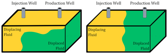
Figure 1.
(Left) pure CO2 injection; (right) CO2–foam injection.
One of the challenges in foam applications is foam stability. Lamellae, as part of the foam, are thermodynamically unstable and easily break. Generally, the stability of foam is influenced by the surfactant as the foaming agent [10]. However, the application of a surfactant is expensive and has a high adsorption rate to the rock surface [11]. Thus, in recent years, nanoparticles have become potentially applicable, especially for conventional good-quality (<5 mD) and unconventional or low-permeability (<0.1 mD) oil reservoirs [12]. One potential nanoparticle to replace the expensive foam booster is fly ash [13]. Fly ash is a coal power plant by-product with excessive quantities, up to 500 million tonnes across the world annually, of which only 25 to 30% is re-utilized in several sectors [14]. The main compound of coal fly ash is SiO2 [15], which is as the most effective foam-stabilizer additive [16]. In this work, the fly ash particle size was reduced to nanoparticles and characterized to improve its effectiveness in stabilizing foam. The aims of this research were to investigate the effect of nano fly ash on foam stability, considering the compounds of the nanoparticles, using static tests where salinity and the presence of oil were observed.
2. Materials and Methods
2.1. Nanoparticle Characterizations
Nanoparticles (NPs) can be characterized by their size and shape, as well as their size distribution, degree of aggregation, and surface area, which influences NP applications. X-Ray Diffraction (XRD) is one of the widely used techniques to characterize NPs. This technique provides chemical information associated with the crystal structure, such as the degree of crystallinity. For this research, XRD was used to investigate the particle compositions and crystal structures of fly ash before and after a mechanical activation process, which reduces the size of the nanoparticles. The results were determined by comparing the position and intensity of the peak with the reference pattern data, which are available from the International Centre for Diffraction Data (ICDD). However, this technique is not suitable for amorphous materials and it exceeds the XRD peak for particle sizes under 3 mm [17]. The other technique is Particle Size Analysis (PSA), which measures the distributions of particle sizes with equivalent spherical diameters (D10, D50, D90) for both liquid and powder samples [18]. Using this method, the results are not influenced by the flow behavior and can be obtained rapidly. In addition, the particle shape cannot be investigated through PSA. For this research, there were two types of nano fly ash (NFA) that were observed, which are Type F and Type C. This classification is based on chemical compounds such as SiO2, which is the main compound used to stabilize foam.
2.2. Foam Stability Test
Bulk foam is a method used in this research to test foam stability. This method was conducted with an ambient temperature and pressure using a graduated cylinder to investigate the effect of adding nano fly ash (NFA) on the stability of foam. Alpha Olefin Sulfonate, as an anionic surfactant, which is applied as a foaming agent, was dissolved in brine at a constant concentration of 0.7 wt%. Additional variables, which were the type of fly ash, light oil, and salinity (NaCl), were also observed. The constant concentration of each variable was 1 wt% for NFA, 5 wt% for light oil, and 2 wt% for NaCl.
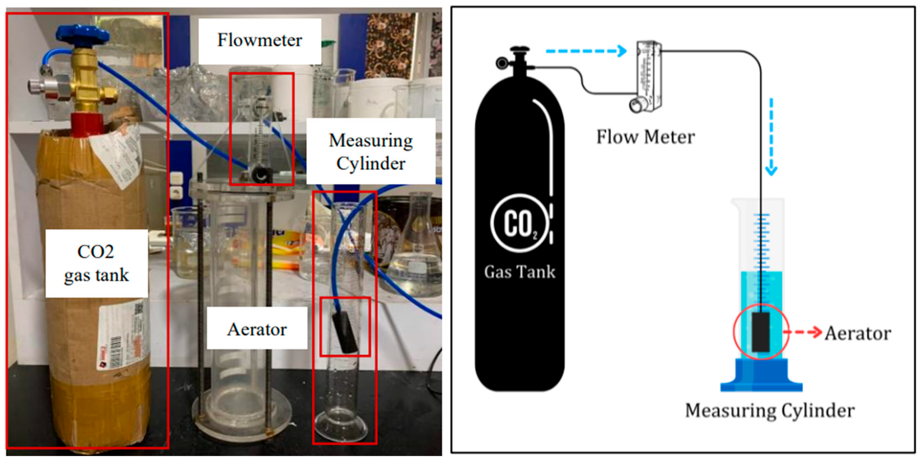
The foam stability test was conducted using a 250 mL glass graduated cylinder and several other components, as shown in Figure 1. An aerator as porous media, to generate uniform bubble foam, was connected to a CO2 gas tank through a PVC pipe. The flow rate of the CO2 gas was set constant at 0.2 L/min using a flow meter. CO2 gas was injected for 1 min, and then, the foam started to generate. After that, the column height of the foam was recorded. At that point, the time at which the foam had decayed to half the initial volume was recorded as the half-life times.
3. Results
3.1. X-Ray Diffraction (XRD)
The particle compositions of Type-C and Type-F NFA were investigated via X-Ray Diffraction or XRD, as shown in Table 1. For Type-C NFA, before the mechanical activation process, the highest mineral content was Quartz or SiO2 at 50%. After reducing the size of the nanoparticles, the content changed and had additional compounds. The Quartz content decreased to 9.2%, and the other compound with the highest content was Calcium Cyclo-Hexaaluminate (Ca3Al2O6) at 43.7%. The other result of XRD was Type-F NFA, which was similar to Type C, in that before the mechanical activation process, the highest content was Quartz or SiO2 at 93.8%. Then, the compounds changed after the mechanical activation process, of which Quartz (SiO2) was 59.7%.

Table 1.
Comparing compounds of fly ash before and after the mechanical activation process.
3.2. Particle Size Analysis
The result of the Particle Size Analysis (PSA) for this research was not only the size of the particles but also the Polydispersity Index (PI), which analyzes the particle size distribution, as shown in Table 2. Before the mechanical activation process, the particle size of Type-C NFA was 1923.7 nm or 1.9 µm, and Type F was 4279.2 nm or 4.3 µm. Then, after that process, the size of the particles was successfully decreased, for which Type-C NFA was 409.8 nm and Type F was 640.8 nm.
Table 2.
Particle Size Analysis result.
3.3. Bulk Foam Test
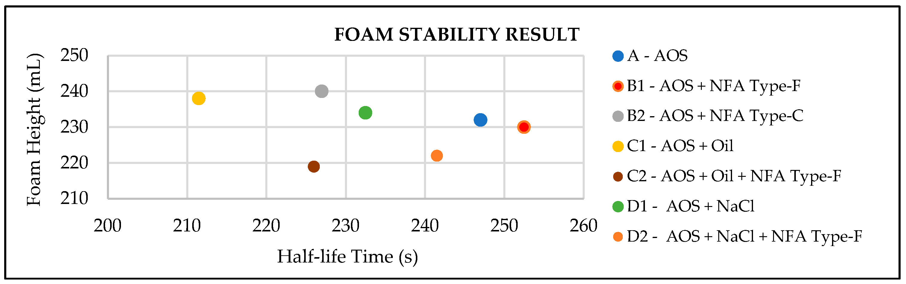
After investigating the nano fly ash (NFA) characteristics, the bulk foam test was conducted, for which the result is shown in Figure 2 and listed in Table 3. The first experiment was to screen how effective the two types of NFAs were in stabilizing the foam. Sample B1 and B2 interpreted the application of Type-F and Type-C NFA, respectively. From the half-life times, the conclusion was that Type-F NFA has a longer time to decay, rather than Type C. This means that the foam was more stable using Type F as a stabilizer. Afterwards, this research applied additional conditions, which were used to investigate the effect of adding oil and salinity. The result showed that the stability of foam was influenced by oil and salinity, which was interpreted by Sample A, C1, and D1. Thus, Type-F NFA, as the most effective stabilizer foam, was applied. It successfully increased the half-life times, which is shown by comparing Sample C1 and C2 as the effect of adding oil, while Sample D1 and D2 was the effect of increasing the salinity.
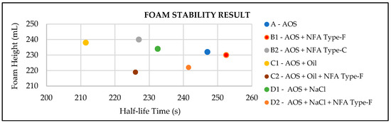
Figure 2.
Foam stability test results.
Table 3.
Foam stability test results.
4. Discussion
4.1. Nanoparticle Characteristizations
The mechanical activation process of fly ash was successful in reducing the particle size of nanoparticles, which was shown in the result of the particle characterization. Using X-Ray Diffraction (XRD), compounds of fly ash changed along with the particle size decreasing. This indicates that the crystal structure was changed to become amorphous. The other compounds that occurred were influenced by many factors. The possibility of the factors was due to new crystal structure formation after the mechanical activation process [19] or there were other contaminants during the process.
After the mechanical activation process, fly ash turned into nanoparticles, which were 409.8 nm for Type C and 640.8 nm for Type F. Particle Size Analysis (PSA) resulted in other parameters besides the particles size, which including the Polydispersity Index (PI). The result of the PI for both nano fly ash (NFA) types was below 0.5, which were 0.293 (Type-C) and 0.304 (Type-F). This indicates that the NFA size was quite uniform as the particle size distribution was tight because the PI value was less than 0.5 [20].
4.2. Nano Fly Ash Effect on Foam Stability
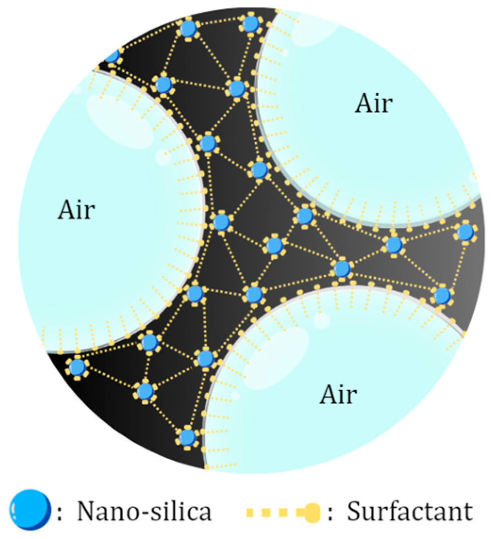
Type-F nano fly ash (NFA) successfully became a foam stabilizer, which improved the half-life time from 247 to 252.5 s. This was caused by rich silica compounds that are able to adsorb into the gas–liquid interface and form foam structures that are more stable, as shown in the schematic in Figure 3. However, the application of NFA at excessive concentrations can cause aggregation and precipitation in the foam film interface that causes damage to foam stability [21]. Besides the NFA concentrations, its type also influences foam stability due to NFA compounds. The result showed that Type-C NFA decreased the half-life time to 227 s. The content of Ca2+ in the Type-C NFA may cause precipitation during the flooding process, which will decrease the concentration of surfactant on the lamella [22]. In addition, due to the high content of CaO, Type-C NPs have cementitious characteristics, which may occur as coagulation if it contacts water [23]. Thus, for a further procedure, this research continued to use Type-F fly ash, which has a high content of SiO2, which may increase the foam strength and interface film viscosity to improve foam stability.
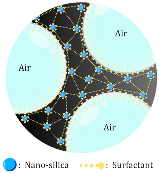
Figure 3.
Schematic of silica nanoparticles stabilizing foam.
4.2.1. Foam Stability in Light Oil Presence
The presence of light oil influenced the foam stability, which decreased the half-life time from 247 to 212.5 s. This occurred due to many factors. Oil emulsion droplets, which have smaller particles rather than the lamella, may break the gas–liquid interface. This is because the oil droplets spread out on the lamella surface and then force the liquid to discharge from the film to plateau borders, which causes a thinner film and breakage of the foam. If the oil droplets do not spread out, they will coalesce creating a lens shape on the gas–liquid interface, which breaks the bubble film if it gets into the lamella [24]. By adding Type-F NFA as nanoparticles, it adsorbed on the gas–liquid interface, which charged the foam surface. The bubbles, which have the same charge, repel each other, thus creating the lamellae thickener [25]. Thus, the foam film was more stable when Type-F NFA was applied, which improved the half-life time from 212.5 to 226 s.
4.2.2. Foam Stability in Salinity Conditions
Foam is influenced by salinity, as shown in Figure 4. In this research, salinity was increased by adding 2 wt% NaCl to investigate the foam stability, which resulted in a decrease in the half-life time from 247 to 232.5 s. In the absence of Type-F NFA, salinity reduced the foam stability because of the destruction of electrostatic forces between lamellae. This occurred because the disjoining pressure is reduced, which results in decreasing foam stability [26]. Additionally, when Type-F NFA was added, the foam stability was not improved significantly, and it was not as stable as in the absence of salinity. It only improved from 232.5 to 241.5 s. The presence of high salinity in nanoparticle applications may increase the Van der Waals forces and decrease repulsive electrostatic forces of nanoparticles. Thus, it decreases the zeta potential, which accelerates the aggregation rate of nanoparticles [27].
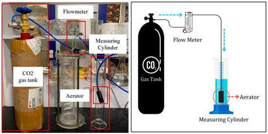
Figure 4.
Schematic of foam stability test.
5. Conclusions
This study conducted tests for applying fly ash as nanoparticles to stabilize foam. Through a laboratory experiment, it was concluded that nano fly ash is suitable for foam stabilizers for both additional conditions of the presence of oil and salinity.
- 1 wt% Type-F nano fly ash (NFA) stabilized the foam, which was observed by increasing the half-life time, which has been shown in Sample B1, C2, and D2.
- Type-C NFA was not suitable as a foam stabilizer due to the cementitious characteristics because it contains high CaO, which decreased the half-life time of the foam.
- The presence of light oil caused foam film rupture, which could be prevented by adding Type-F NFA as a foam stabilizer.
- Adding 2 wt% NaCl to increase the salinity decreased the zeta potential value, which made the foam film more unstable, and adding Type-F NFA did not result in a significant improvement in foam stability due to aggregation rate acceleration.
The existing NFA analysis was conducted using raw materials of fly ash that contained several compounds, which disrupted the process of silica stabilization in the foam. Therefore, the mechanism by which the main compound of NFA, silica, stabilizes foam is not fully understood. Also, it is crucial to apply the reservoir conditions when investigating how silica can withstand harsh conditions. Thus, further in-depth analysis is required in the future.
Author Contributions
Conceptualization, G.W.R. and A.A.P.; methodology, G.W.R.; validation, G.W.R. and A.A.P.; formal analysis, G.W.R.; investigation, G.W.R.; resources, G.W.R.; data curation, G.W.R.; writing—original draft preparation, G.W.R.; writing—review and editing, G.W.R., A.A.P., D.A.M., M.Y. and H.I.; supervision, S.R. and A.A.P.; project administration, A.A.P.; funding acquisition, A.A.P., M.Y. and H.I. All authors have read and agreed to the published version of the manuscript.
Funding
This research was funded by Universitas Pertamina and PT. GMJ Global Energy.
Institutional Review Board Statement
Not applicable.
Informed Consent Statement
Not applicable.
Data Availability Statement
Data are contained within the article.
Acknowledgments
The authors would like to express their sincere gratitude to Universitas Pertamina PT. GMJ Global Energy and the Clean Energy Technologies Research Institute (CETRI), University of Regina, Canada, for providing resources to carry out this study and for their funding and administrative support. Moreover, the authors appreciate PT Nanotech Indonesia Global Tbk for being a material supplier. Also, the authors would like to extend their gratitude to Universiti Teknologi PETRONAS in providing access to academic resources.
Conflicts of Interest
The authors declare no conflicts of interest.
References
- Cui, K.; Li, H.; Chen, P.; Li, Y.; Jiang, W.; Guo, K. New Technique for Enhancing Residual Oil Recovery from Low-Permeability Reservoirs: The Cooperation of Petroleum Hydrocarbon-Degrading Bacteria and SiO(2) Nanoparticles. Microorganisms 2022, 10, 2104. [Google Scholar] [CrossRef] [PubMed]
- Sircar, A.; Rayavarapu, K.; Bist, N.; Yadav, K.; Singh, S. Applications of nanoparticles in enhanced oil recovery. Pet. Res. 2022, 7, 77–90. [Google Scholar] [CrossRef]
- Liao, G.; He, D.; Wang, G.; Wang, L.; Wang, Z.; Su, C.; Qin, Q.; Bai, J.; Hu, Z.; Huang, Z.; et al. Discussion on the limit recovery factor of carbon dioxide flooding in a permanent sequestration scenario. Pet. Explor. Dev. 2022, 49, 1463–1470. [Google Scholar] [CrossRef]
- Dziejarski, B.; Krzyżyńska, R.; Andersson, K. Current status of carbon capture, utilization, and storage technologies in the global economy: A survey of technical assessment. Fuel 2023, 342, 127776. [Google Scholar] [CrossRef]
- Environmental Protection Agency. Inventory of U.S. Greenhouse Gas Emissions and Sinks; U.S. Environmental Protection Agency: Washington, DC, USA, 2023. [Google Scholar]
- Massarweh, O.; Abushaikha, A.S. A review of recent developments in CO2 mobility control in enhanced oil recovery. Petroleum 2022, 8, 291–317. [Google Scholar] [CrossRef]
- Enick, R.M.; Olsen, D.; Ammer, J.; Schuller, W. Mobility and Conformance Control for CO2 EOR via Thickeners, Foams, and Gels—A Literature Review of 40 Years of Research and Pilot Tests. In Proceedings of the Eighteenth SPE Improved Oil Recovery Symposium, Tulsa, OK, USA, 14–18 April 2012; Society of Petroleum Engineers: Dallas, TX, USA, 2012. [Google Scholar]
- Tungdumrongsub, S.; Muggeridge, A. Layering and Oil Recovery: The Impact of Permeability Contrast, Gravity, Viscosity and Dispersion. In Proceedings of the SPE EUROPEC/EAGE Annual Conference and Exhibition, Barcelona, Spain, 14–17 June 2010; Society of Petroleum Engineers: Dallas, TX, USA, 2010. [Google Scholar]
- Føyen, T.; Alcorn, Z.; Fernø, M.; Barrabino, A.; Holt, T. CO2 mobility reduction using foam stabilized by CO2- and water-soluble surfactants. J. Pet. Sci. Eng. 2021, 196, 107651. [Google Scholar] [CrossRef]
- AlYousif, Z.; Kokal, S.; Alabdulwahab, A.; Gizzatov, A. CO2-Foam Rheology: Effect of Surfactant Concentration, Shear Rate and Injection Quality. In Proceedings of the SPE Kingdom of Saudi Arabia Annual Technical Symposium and Exhibition, Dammam, Saudi Arabia, 23–26 April 2018; Society of Petroleum Engineers: Dallas, TX, USA, 2018. [Google Scholar]
- Agrawal, D.; Xu, K.; Darugar, Q.; Khabashesku, V. Enhanced Oil Recovery by Nanoparticle-Induced Crude Oil Swelling: Pore-Scale Experiments and Understanding. In Proceedings of the SPE Asia Pacific Oil & Gas Conference and Exhibition, Brisbane, Australia, 23–25 October 2018; Society of Petroleum Engineers: Dallas, TX, USA, 2018. [Google Scholar]
- Afekare, D.; Garno, J.; Rao, D. Enhancing oil recovery using silica nanoparticles: Nanoscale wettability alteration effects and implications for shale oil recovery. J. Pet. Sci. Eng. 2021, 203, 108897. [Google Scholar] [CrossRef]
- Yang, Y.; Cheng, T.; You, Z.; Liang, T.; Hou, J. Profile Control Using Fly Ash Three-Phase Foam Assisted by Microspheres with an Adhesive Coating. Appl. Sci. 2021, 11, 3616. [Google Scholar] [CrossRef]
- Mathapati, M.; Amate, K.; Prasad, C.D.; Jayavardhana, M.; Raju, T.H. A review on fly ash utilization. Mater. Today Proc. 2022, 50, 1535–1540. [Google Scholar] [CrossRef]
- Zhang, Y.; Liu, Q.; Ye, H.; Yang, L.; Luo, D.; Peng, B. Nanoparticles as foam stabilizer: Mechanism, control parameters and application in foam flooding for enhanced oil recovery. J. Pet. Sci. Eng. 2021, 202, 108561. [Google Scholar] [CrossRef]
- Ibrahim, A.F.; Nasr-El-Din, H.A. CO2 Foam for Enhanced Oil Recovery Applications. In Foams—Emerging Technologies; Intechopen: London, UK, 2019. [Google Scholar]
- Mourdikoudis, S.; Pallares, R.M.; Thanh, N.T.K. Characterization techniques for nanoparticles: Comparison and complementarity upon studying nanoparticle properties. Nanoscale 2018, 10, 12871–12934. [Google Scholar] [CrossRef] [PubMed]
- Blott, S.J.; Croft, D.J.; Pye, K.; Saye, S.E.; Wilson, H.E. Particle size analysis by laser diffraction. Geol. Soc. Lond. Spéc. Publ. 2004, 232, 63–73. [Google Scholar] [CrossRef]
- Hitesh; Wattal, R.; Lata, S. Development and characterization of coal fly ash through low-energy ball milling. Mater. Today Proc. 2021, 47, 2970–2975. [Google Scholar] [CrossRef]
- Rao, S.; Song, Y.; Peddie, F.; Evans, A. Particle size reduction to the nanometer range: A promising approach to improve buccal absorption of poorly water-soluble drugs. Int. J. Nanomed. 2011, 6, 1245–1251. [Google Scholar]
- Phong, G.M.; Pilus, R.M.; Mustaffa, A.; Thangavel, L.; Mohamed, N.M. Relationship between fly ash nanoparticle-stabilized-foam and oil production in core displacement and simulation studies. Fuel 2020, 266, 117033. [Google Scholar] [CrossRef]
- Sugihardjo, S. Surfactant Properties Evaluation for Chemical Flooding. Sci. Contrib. Oil Gas 2008, 31, 34–39. [Google Scholar] [CrossRef]
- Eftekhari, A.A.; Krastev, R.; Farajzadeh, R. Foam Stabilized by Fly Ash Nanoparticles for Enhancing Oil Recovery. Ind. Eng. Chem. Res. 2015, 54, 12482–12491. [Google Scholar] [CrossRef]
- Osei-Bonsu, K.; Shokri, N.; Grassia, P. Foam stability in the presence and absence of hydrocarbons: From bubble- to bulk-scale. Colloids Surf. A Physicochem. Eng. Asp. 2015, 481, 514–526. [Google Scholar] [CrossRef]
- Ibrahim, A.F.; Nasr-El-Din, H.A. Stability Improvement of Carbon Dioxide Foam Using Nanoparticles and Viscoelastic Surfactants for Enhanced-Oil-Recovery Applications. SPE Reserv. Eval. Eng. 2020, 23, 414–430. [Google Scholar] [CrossRef]
- Emami, H.; Tanha, A.A.; Manshad, A.K.; Mohammadi, A.H. Experimental Investigation of Foam Flooding Using Anionic and Nonionic Surfactants: A Screening Scenario to Assess the Effects of Salinity and pH on Foam Stability and Foam Height. ACS Omega 2022, 7, 14832–14847. [Google Scholar] [CrossRef] [PubMed]
- Latif, W.M.S.M.; Sharbini, S.N.; Sulaiman, W.R.W.; Idris, A.K. Utilization of silicon dioxide nanoparticles in foam enhanced oil recovery—A comprehensive review. In Proceedings of the 1st International Postgraduate Conference on Mechanical Engineering (IPCME2018), Pahang, Malaysia, 31 October 2018. [Google Scholar]

Disclaimer/Publisher’s Note: The statements, opinions and data contained in all publications are solely those of the individual author(s) and contributor(s) and not of MDPI and/or the editor(s). MDPI and/or the editor(s) disclaim responsibility for any injury to people or property resulting from any ideas, methods, instructions or products referred to in the content. |
© 2025 by the authors. Licensee MDPI, Basel, Switzerland. This article is an open access article distributed under the terms and conditions of the Creative Commons Attribution (CC BY) license (https://creativecommons.org/licenses/by/4.0/).