Abstract
Machining is a critical aspect of metalworking since it is used to cut metal. Machine tools, particularly cutting tools, are critical in metalworking for successful metal cutting. They have a significant role in developing distinct shapes and forms. Machining has become more crucial in modern automated manufacturing systems because of the massive upsurge in production time and the necessity to offset the high capital cost. Specifically, the Taguchi approach is used in this experiment because it uses an orthogonal array to investigate the parameters through a fixed number of experiments. In this case, three parameters (speed, depth of cut, and feed) were combined to produce nine possible result combinations. Stainless steel and mild steel are machined with the help of a ceramic tool insert with certain combinations. This is performed to estimate tool wear and surface roughness. The comparative study was conducted for two different materials: stainless steel (SS) and mild steel (MS).
1. Introduction
A main machining process called turning involves cutting metal and removing chips to create final products with the correct size, shape, and surface roughness. Choosing the appropriate machining parameters for a certain product may be challenging. Indeed, it is determined by the expertise of the engineers and the design table for machine tools. As a result, optimisation is more important than ever to fulfill the needs of the machined item in terms of cost and quality. The main objective of Taguchi’s design was to make sure the product works effectively in noisy environments, which increases the likelihood that it will last a long time. The Taguchi technique is easy to use and does not require much work. As a result, a variety of businesses are using Taguchi’s technology to raise the caliber of their production procedures. Important factors in the machining process are the cutting force and surface roughness. Cutting forces have an influence on the exactness of the workpiece’s dimensions, its deformation, and its chip formation. In industries, a minimum of ten components through precise surface roughness is always necessary to meet consumers’ requirements. This is possible through the optimisation route, which is the subject of this research.
S. K. Thangarasu et al. [1] explored a turning process, and the estimation of cutting forces was performed. Turning with an enriched cutting tool has various advantages over grinding, the most notable of which is a reduced cycle time. Cutting fluid is not required, which upsurges the expanse of time available, the flexibility of the operation, the suitability of the MRR, surface unevenness, and a typical environmental effect. Cutting forces delivered to a MS workpiece by a cemented carbide insert tool were measured via a full-bridge dynamometer at different depths of cut and speed of cut, along with feed rates. Experiments were designed following Taguchi principles. The measured cutting forces were associated with the expected ones to determine a feasible proposed design.
Manoj Nayak et al. [2] examined the mechanical, microstructure, and machining properties of D6 steel in both the annealed and hardened stages. Researchers discovered that the feed rate and depth of cut (DOC) impact surface roughness. However, the feed rate and DOC have a major effect on the foremost cutting force. When machining annealed steel, cutting speed does not distress surface roughness and is the major driving factor for the cutting action. High cutting speeds besides a medium depth of cut resulted in significant wear.
C Moganapriya et al. [3] showed that cutting speed (43.1 percent) and DOC (35.8 percent) were the most critical drivers of tool wear. Although the usage of cutting fluid (13.7 percent) drastically impacted the tool wear, the feed rate was shown to be the most critical factor in determining tool wear. L. A. Looney et al. [4] found that obtaining the desired surface finish when cutting on a low feed rate requires ideal cutting conditions. The occurrence of roughness plus tool wear was seen when cutting at high speed and with a medium DOC.
A. J. Makadia et al. [5] showed that the DOC had a strong influence on MRR and, also, on the cutting speed, although the DOC followed via the feed had the most excellent effect on the amalgamation of the two. Turning tests were conducted on an AISI 1020 mild steel workpiece whose nose radius was a 0.8 mm carbide insert. The impact of various constraints, like the feed rate, DOC, and cutting speed, on the roughness of the machined surface was examined.
S. Debnath et al. [6] used the orthogonal array-based Taguchi technique to conduct the minimum number of experiments. The feed rate effect was shown to significantly contribute to the workpiece’s surface roughness, accounting for 34.3 percent of the total. In addition, the flow velocity of the cutting fluid had a momentous influence on the outcome (33.1 percent). In contrast, the DOC and the cutting speed had only minimal control over the surface unevenness of the cut material.
R. Suresh et al. [7] discovered that multilayer coating on carbide substrates, compared with uncoated carbide tools, increases the tool’s lifespan while simultaneously decreasing the cutting force. Models for second-order mathematical analysis were used to investigate the impact of cut depth on machining physiognomies—for instance, surface roughness, tool wear, explicit cutting force and machining power, and force—while machining chromium-based materials.
Experiments have demonstrated that extending tool life can lead to less tool wear. By combining the force constituents applied to the cutting tool, the overall work produced by machining with a cutting tool was computed. Increasing the feed rate, cutting speed, and DOC results in a rise in tool temperature, which shortens the tool’s useful life. In response to the rise in feed and primary cutting force at the chip and tool interface, an upsurge in temperature was observed; however, this temperature decreased with the rise in the DOC [8,9,10]. These studies have exposed that increasing the speed of the cut results in lowered cutting tool forces and lowered temperature of machined surfaces [11]. Further research revealed that tool wear was accountable for the increased temperature of the machined surface and cutting tool forces [12]. The chip’s temperature increased as the cutting speed improved [13].
2. Experimental Details
2.1. Stainless Steel 304
The utmost prevalent kind of SS is SAE 304 as shown in Figure 1 used for the experimental work. The crucial non-iron constituents of steel are nickel (8–10.5%) and chromium (18–20%) [1]. This kind of SS is austenitic compared with carbon steel, it has lesser electrical and thermal conductivity. While still magnetic, it is not as magnetic as steel. Since it is easier to mould into diverse forms, it is more extensively utilised and has a tougher erosion resistance than ordinary steel.
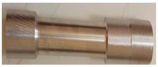
Figure 1.
Stainless steel specimen.
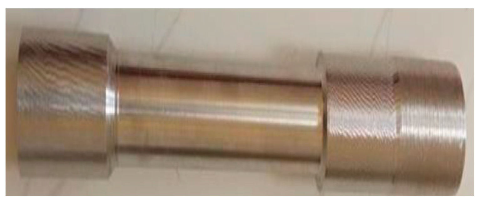
2.2. Mild Steel 1020
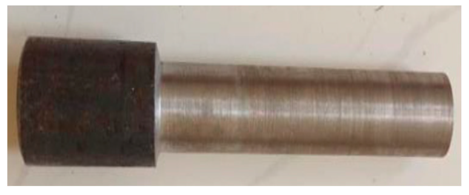
Mild steel 1020 shown in Figure 2 used for the research work is a common-purpose low tensile carbon steel with low hardenability properties, normally delivered in the cold drawn, turned, and polished situations, with a distinctive tensile strength range of 410–790 Mpa, and 119–235 Brinell hardness range.

Figure 2.
Mild steel specimen.
2.3. Profile Projector
Profile projector is used to compare measured contour models and complex shape stampings. It is simple and effective and is a standard optical instrument that measures around 360°, so the screen’s X-Y axis aligns with a straight edge of the machined item. This projection screen is expanded to provide an easier linear measurement while displaying the specimen’s profile. The edge of the specimen might line up with the grid on the screen. Simple distance measurements may be taken from there. This is carried out on a larger specimen profile, which makes measurement easier and less error-prone. The enlarged projection screen of a profile projector is utilised in the most widely used lighting method called diascopic illumination, sometimes referred to as transmitted illumination. An opaque specimen is translucent and light-permeable; light cannot travel through it, but it will define the specimen’s profile. On the screen, the sample may be measured. There will be episcopic lighting in addition to a profile projector illuminating overhead. This displays any inside locations or bores that require measurement and cleaning. This standard optical instrument measurement is simple and effective and is used for intricate stampings, gears, cams, threads, and the contour model.
2.4. Surfcom Flex
Surfcom Flex shown in Figure 3 is easy to use and it boosts shop floor operability. It takes only three button presses to accomplish a measurement. An essential attachment, a strap, can be added to either side mini-USB connector with Surfcom Flex for PC connection. The data can be transmitted to a PC for analysis.
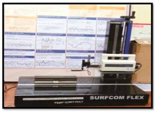
Figure 3.
Surfcom Flex used for experimental work.
2.5. Tool Holder and Tool Insert
The tool holder which is shown in Figure 4a is a universal term for connectors used to mount the cutting tools in the machine tool equipment that accomplishes numerous processes. It impacts the machining accurateness of machine tools plus the product quality, so they can claim high exactness for which not even microscopic inaccuracy is endurable.
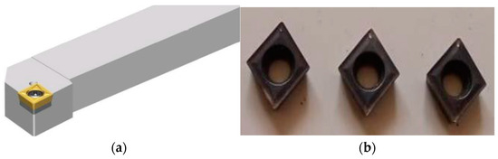
Figure 4.
(a) Tool holder and (b) tool insert.
Ceramic tool inserts shown in Figure 4b have become essential insert materials as they have high thermo-stability, wear resistance, and high resistance to corrosion. Because they can resist temperatures up to 2204 °C, the work material can be softened, allowing deeper and cleaner cuts. Ceramic tools are manufactured using the powder metallurgy technique from aluminum oxide (Al2O3) or silicon nitride compounds combined with additions like titanium oxide and magnesium oxide to enhance cutting characteristics. In addition to their high hardness, ceramic materials can keep their qualities at extremely high temperatures, have excellent electrical and wear resistance, and chemical inertness, all of which make them the ultimate choice for tooling. At temperatures above 537 degrees Celsius (2320 degrees Fahrenheit), the metallic binders in carbide and cement tools begin to weaken, but ceramic tools remain solid.
3. Results and Discussion
Table 1 demonstrates how cutting parameters such as speed (112, 180, 280), feed (0.045, 0.070, 0.125), and DOC (0.5, 1.0, 1.5) are chosen for assessing surface roughness plus tool wear while turning stainless steel and mild steel with ceramic-based tool inserts.

Table 1.
Cutting parameters.
Numerous cutting constraints were selected for an in-depth understanding of the machining process. The detailed selected constraints are displayed in Table 1. The various processes carried out were grouped with the suitable name and are presented in Table 2.
Table 2.
Experimental results of turning stainless steel.
Table 2, Figure 5 and Figure 6 displays several metrics for stainless steel resulting from the profile projector and Surfcom Flex, such as the arithmetical mean roughness value (RA) in μm, mean roughness depth (RZ) in μm, total height of the profile (RT) in μm, reduced peak height (RPK) in μm, and tool wear in μm
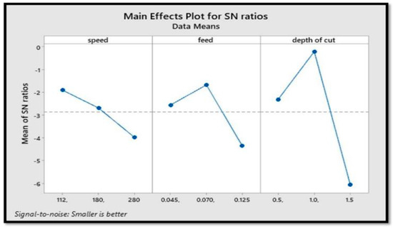
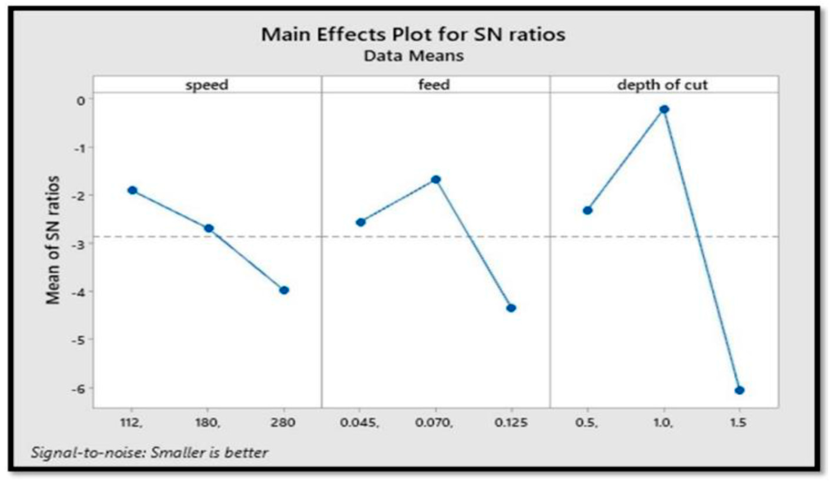
Figure 5.
Stainless steel surface roughness vs. depth of cut, speed, and feed.
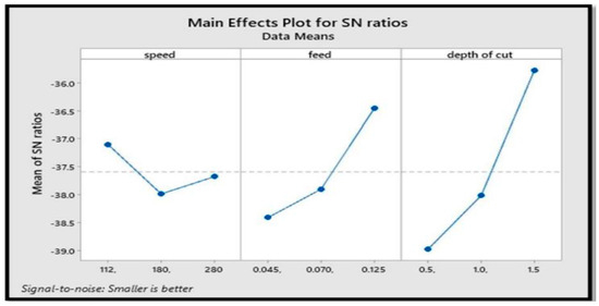
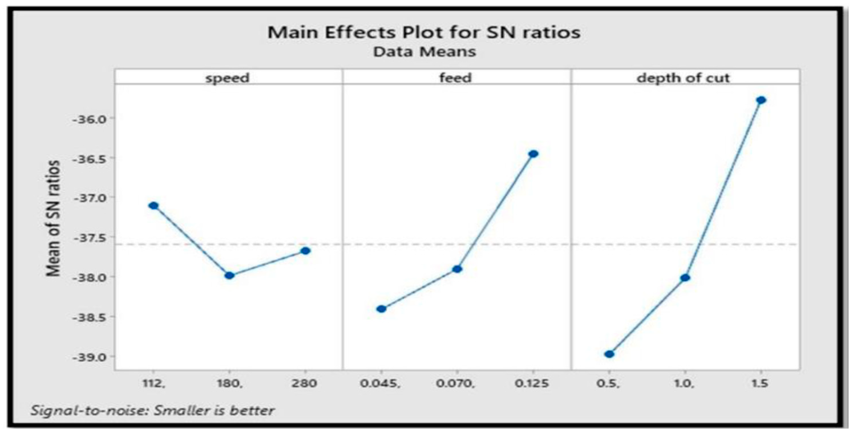
Figure 6.
Tool wear vs. speed, feed, and depth of cut.
To assess tool wear and surface roughness, mild steel is turned using a ceramic tool insert. The following Table 3, Figure 7 and Figure 8 displays the RA (μm), RZ (μm), RT (μm), RPK (μm), and tool wear acquired using the profile projector and Surfcom Flex.
Table 3.
Experimental results of turning mild steel.
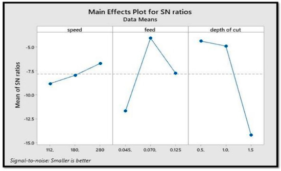
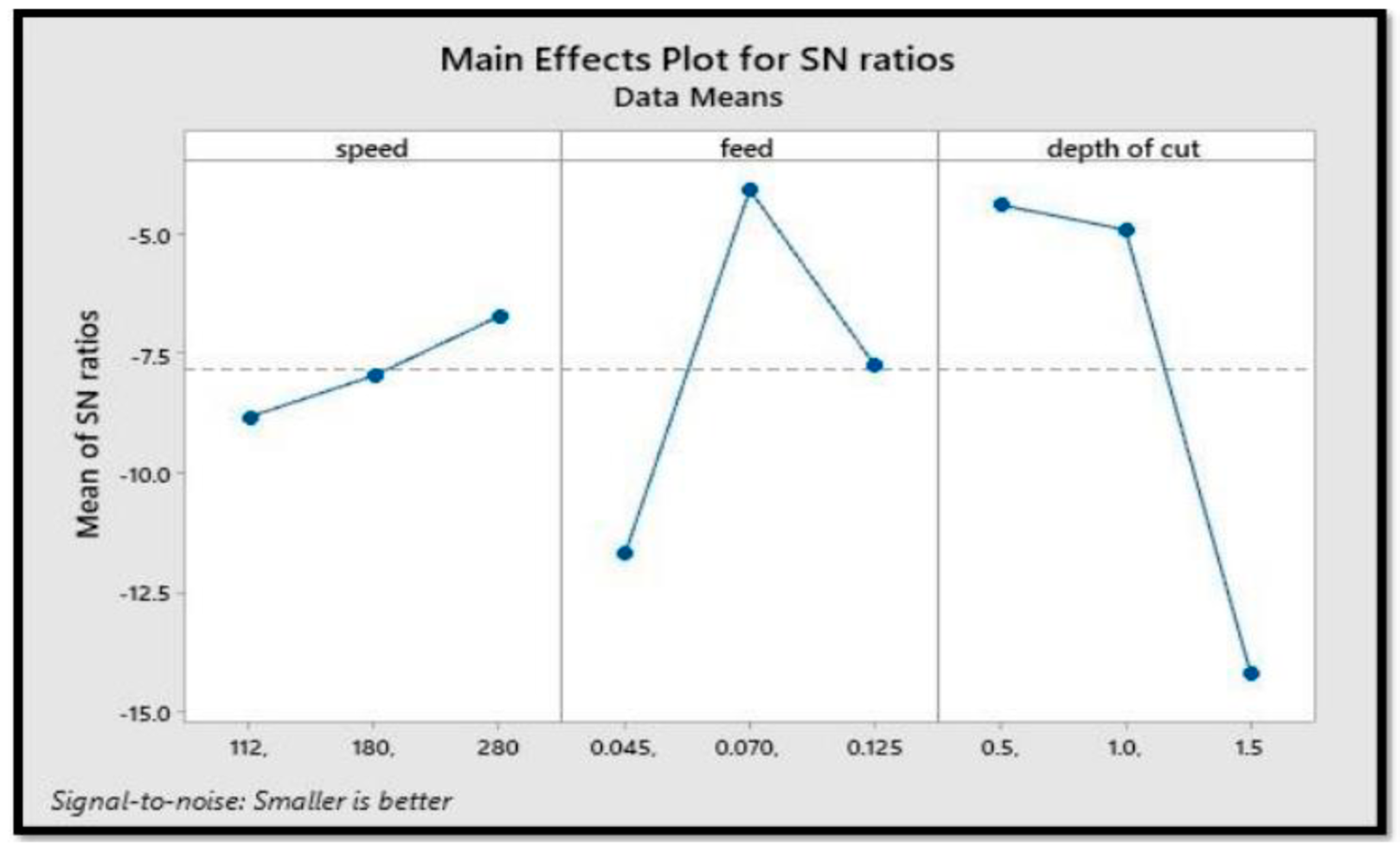
Figure 7.
Mild steel surface roughness vs. speed, feed, and DOC.
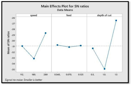
Figure 8.
Tool wear vs. speed, feed, and depth of cut of mild steel.
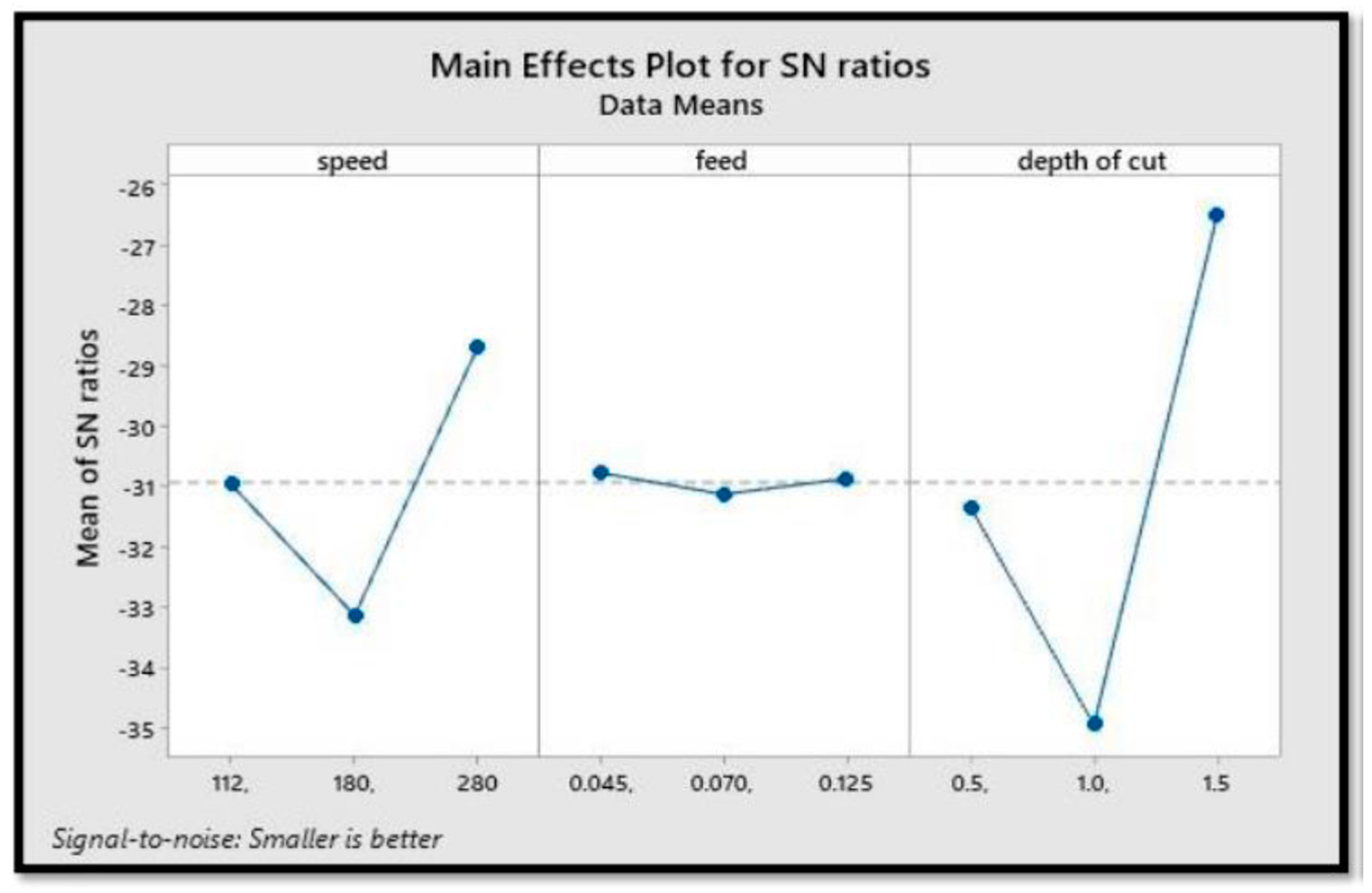
When the quality physiognomy is continuous for engineering analysis, the S/N ratio characteristics may be classified into three stages: the smaller the better, the more nominal the better, and the higher the better. The smaller the better characteristic’s S/N ratio was used in the experiment to determine the ideal tool wear rate and to minimise surface irregularities in the workpiece.
4. Conclusions
This study aims to see if Taguchi’s orthogonal array can forecast surface unevenness of tool wear when machining SS and MS with ceramic tool inserts while keeping factors like speed, feed, and DOC in mind.
Because of the high strength of stainless steel, tool wear is the highest compared with mild steel. When we look at surface roughness, we see that it impacts parameters like speed, feed, and DOC. For higher feed, the surface unevenness is low, and tool wear is also low when we talk about the DOC. The surface irregularity will diminish as the spindle speed increases.
Considering the above parameters, the average surface irregularity for SS at the speed of 180, feed of 0.045, and DOC of 1.0 is 0.583, which is the lowest among all orthogonal arrays. For mild steel at the speed of 280, feed of 0.070, and DOC of 0.5, the average surface roughness value is 0.825, the lowest among all orthogonal arrays. The material, speed, feed, and DOC all influence surface roughness.
Author Contributions
Conceptualization, S.R. and J.I.H.; methodology, S.R. and J.I.H.; investigation, S.R. and P.R.J.; resources, S.R., J.I.H. and P.R.J.; data curation, M.C.P.S., B.V. and K.S.V.; writing—original draft preparation, S.R., J.I.H., P.R.J., M.C.P.S., K.S.V. and B.V.; writing—review and editing, S.R. and P.R.J. All authors have read and agreed to the published version of the manuscript.
Funding
This research received no external funding.
Institutional Review Board Statement
Not applicable.
Informed Consent Statement
Not applicable.
Data Availability Statement
Data are contained within the article.
Conflicts of Interest
The authors declare no conflicts of interest.
References
- Thangarasu, S.K.; Shankar, S.; Thomas, A.T.; Sridhar, G. Prediction of Cutting Force in Turning Process-an Experimental Approach. IOP Conf. Ser. Mater. Sci. Eng. 2018, 310, 012119. [Google Scholar] [CrossRef]
- Nayak, M.; Sehgal, R. Effect of Tool Material Properties and Cutting Conditions on Machinability of AISI D6 Steel During Hard Turning. Arab. J. Sci. Eng. 2015, 40, 1151–1164. [Google Scholar] [CrossRef]
- Moganapriya, C.; Rajasekar, R.; Ponappa, K.; Kumar, P.S.; Pal, S.K.; Kumar, J.S. Effect of coating on tool inserts and cutting fluid flow rate on the machining performance of AISI 1015 steel. Mater. Test. 2018, 60, 1202–1208. [Google Scholar] [CrossRef]
- Looney, L.A.; Monaghan, J.M.; O’Reilly, P.; Taplin, D.M.R. The turning of an Al/SiC metal-matrix composite. J. Mater. Process. Technol. 1992, 33, 453–468. [Google Scholar] [CrossRef]
- Makadia, A.J.; Nanavati, J.I. Optimisation of machining parameters for turning operations based on response surface methodology. Measurement 2013, 46, 1521–1529. [Google Scholar] [CrossRef]
- Debnath, S.; Reddy, M.M.; Yi, Q.S. Influence of cutting fluid conditions and cutting parameters on surface roughness and tool wear in turning process using Taguchi method. Measurement 2016, 78, 111–119. [Google Scholar] [CrossRef]
- Suresh, R.; Joshi, A.G.; Suresh, R.; Joshi, A.G. Investigations on Machinability Characteristics of Hardened AISI H13 Steel with Multilayer Coated Carbide Tool Using Statistical Techniques. Available online: https://services.igi-global.com/resolvedoi/resolve.aspx?doi=10.4018/978-1-5225-2440-3.ch009 (accessed on 7 November 2021).
- Gaitonde, V.N.; Karnik, S.R.; Figueira, L.; Davim, J.P. Analysis of Machinability During Hard Turning of Cold Work Tool Steel (Type: AISI D2). Mater. Manuf. Process. 2009, 24, 1373–1382. [Google Scholar] [CrossRef]
- O’Sullivan, D.; Cotterell, M. Temperature measurement in single point turning. J. Mater. Process. Technol. 2001, 118, 301–308. [Google Scholar] [CrossRef]
- Dogu, Y.; Aslan, E.; Camuscu, N. A numerical model to determine temperature distribution in orthogonal metal cutting. J. Mater. Process. Technol. 2006, 171, 1–9. [Google Scholar] [CrossRef]
- Bensouilah, H.; Aouici, H.; Meddour, I.; Yallese, M.A.; Mabrouki, T.; Girardin, F. Performance of coated and uncoated mixed ceramic tools in hard turning process. Measurement 2016, 82, 1–18. [Google Scholar] [CrossRef]
- Joshi, K.K.; Behera, R.K.; Anurag. Effect of minimum quantity lubrication with Al2O3 Nanofluid on Surface Roughness and its prediction using hybrid fuzzy controller in turning operation of Inconel 600. Mater. Today Proc. 2018, 5 Pt 3, 20660–20668. [Google Scholar] [CrossRef]
- Muthusamy, Y.; Kadirgama, K.; Rahman, M.M.; Ramasamy, D.; Sharma, K.V. Wear analysis when machining AISI 304 with ethylene glycol/TIO2 nanoparticle-based coolant. Int. J. Adv. Manuf. Technol. 2016, 82, 327–340. [Google Scholar] [CrossRef]


Disclaimer/Publisher’s Note: The statements, opinions and data contained in all publications are solely those of the individual author(s) and contributor(s) and not of MDPI and/or the editor(s). MDPI and/or the editor(s) disclaim responsibility for any injury to people or property resulting from any ideas, methods, instructions or products referred to in the content. |
© 2024 by the authors. Licensee MDPI, Basel, Switzerland. This article is an open access article distributed under the terms and conditions of the Creative Commons Attribution (CC BY) license (https://creativecommons.org/licenses/by/4.0/).