Abstract
The study presents an analysis and guide for the synthesis of a spherical shaped gear mesh in kinematic sculptures. The specific conditions for generating such arrangements are investigated, like the mesh condition for constrained gear systems, the geometry of forming gears, possible patterns, choice of dimensions, and number of teeth. The starting geometry is also partially described, which is based on convex polyhedrons. It is a solid three-dimensional figure with flat polygonal faces that are closed, where all the angles between adjacent faces are less than or equal to 180 degrees, and there are no concave regions or indentations in its structure. Two different examples are presented based on two different polyhedrons with different gear arrangements.
1. Introduction
A kinematic sculpture is a form of artistic expression or art installation that incorporates mechanical or moving elements with the aim of achieving dynamic and interactive qualities. The primary focus of kinematic sculptures lies in the exploration of motion, kinetics, and the interaction between form and movement. These sculptures often rely on mechanical principles and engineering techniques to achieve the desired effects. They are characterized by the integration of various mechanisms, such as gears, levers, springs, cam mechanisms, and others, enabling the sculpture to perform complex and visually impressive movements.
In many cases gears play a pivotal role in achieving these outcomes. They allow for the precise positioning and synchronization of movements, as well as the transmission of a constant angular velocity. Various complex gear solutions are used, which can rarely be seen in other branches of mechanical engineering, such as beveloid and hypoloid gears, non-circular gears, etc. Such sculptures often feature the arrangement of gears in a closed loop, where each gear is meshed with at least two neighboring gears. In this context, the careful selection of gear teeth and the angle between the components are of paramount importance for realizing the mechanism’s functionality.
1.1. Possible Starting Geometries for a Spherical Gear Arrangement
In order to arrange gears in a repeating pattern around the surface of a sphere, they have to be divided into repeating shapes. This is known as tessellation [1]. Using regular sided shapes makes it easier to complete the gearing arrangement since repeated patterns of gear meshes can be used. From the literature it is known that the only regular polygons that can possibly tessellate around a sphere are spherical triangles, squares, and pentagons [1]. This leads to the five so-called platonic solids [2]. These are regular polyhedrons, three-dimensional geometric shapes on which all its faces are identical regular polygons. In other words, each face is a congruent polygon with equal sides and angles. The same number of faces meet at each vertex (corner) of the solid. There are exactly five Platonic solids, as shown in Figure 1.
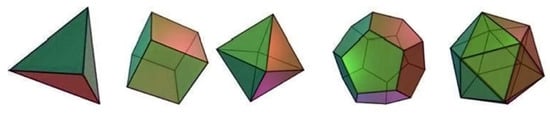
Figure 1.
The five Platonic solids [2].
- Tetrahedron: A tetrahedron has four triangular faces, and three faces meet at each vertex.
- Hexahedron (or Cube): A hexahedron, commonly referred to as a cube, has six square faces, and three faces meet at each vertex.
- Octahedron: An octahedron has eight triangular faces, and four faces meet at each vertex.
- Dodecahedron: A dodecahedron has twelve pentagonal faces, and three faces meet at each vertex.
- Icosahedron: An icosahedron has twenty triangular faces, and five faces meet at each vertex.
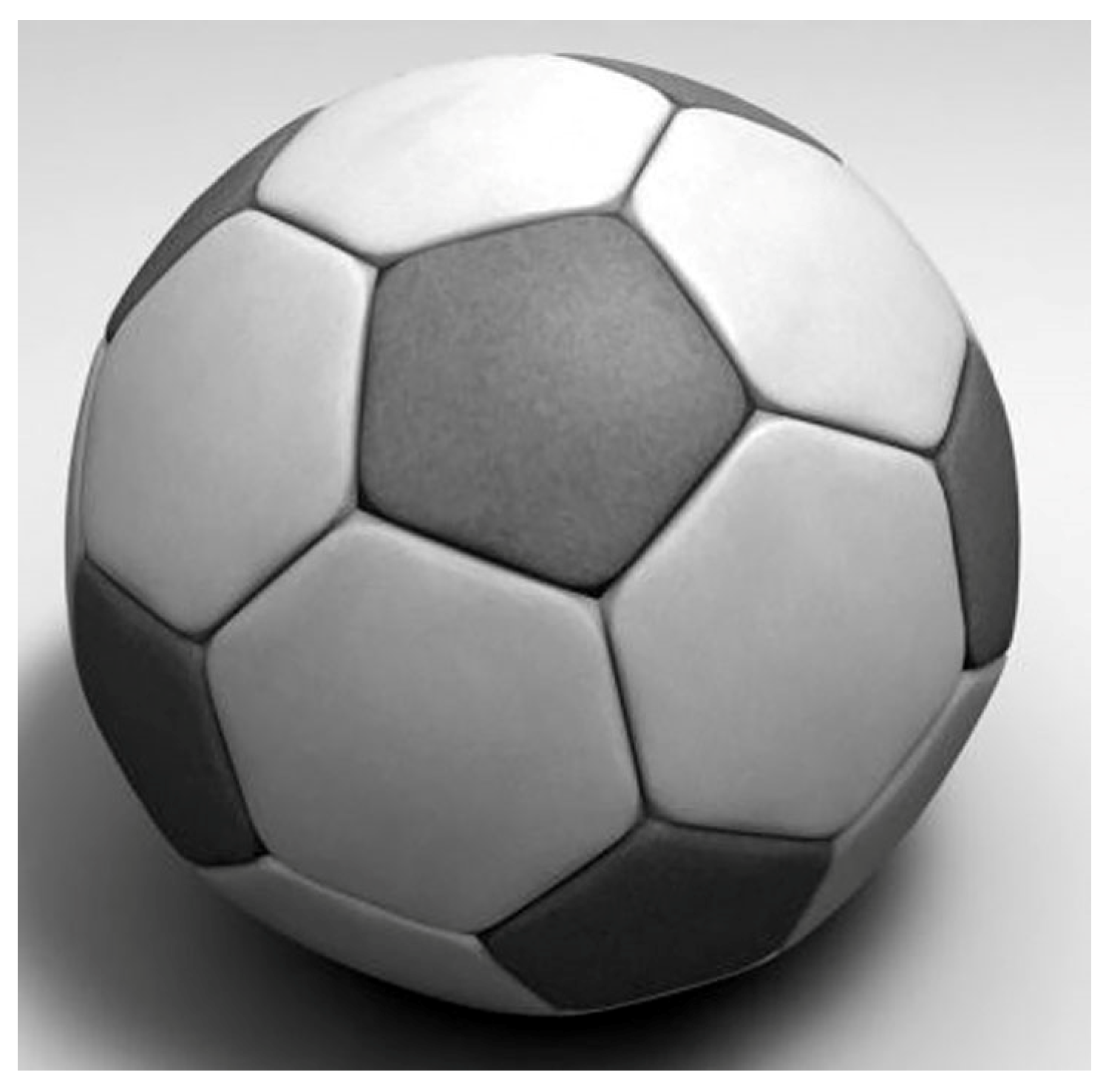
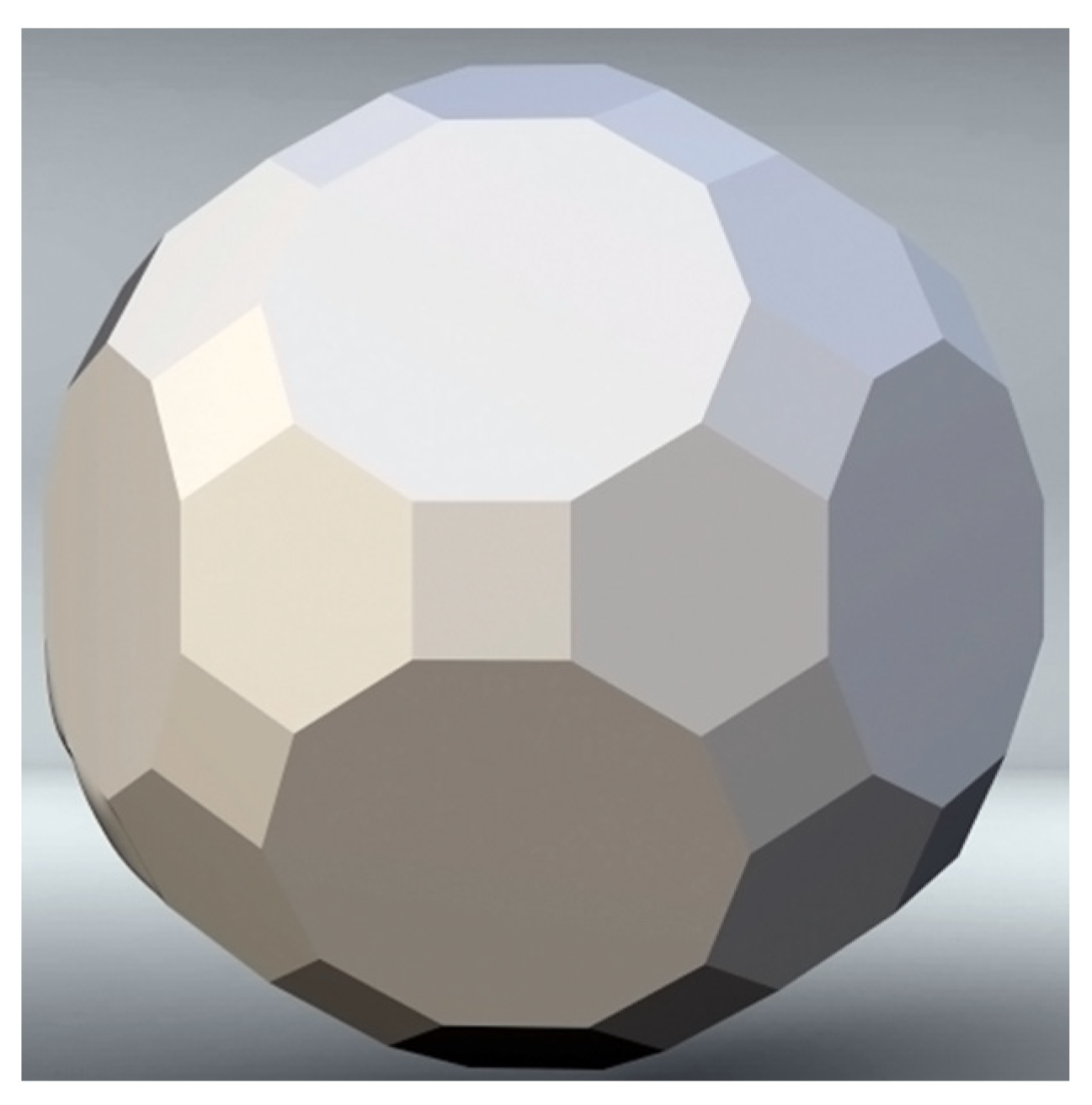
However, truncating (cutting off) the vertices at a uniform distance from the centers of these geometries results in new polyhedrons that are partially regular or “semiregular” because they have faces that are regular polygons (polygons with equal sides and angles), but not all faces are necessarily the same. These are also known as Archimedean solids. There are a total of 13 Archimedean solids, each corresponding to a specific combination of regular polygons as faces. Perhaps the most famous example is the truncated icosahedron used in sports balls, as shown in Figure 2.

Figure 2.
Truncated icosahedron football (soccer ball) [image source—www.free3d.com (accessed on 10 August 2023)].
1.2. Gear Mesh Considerations
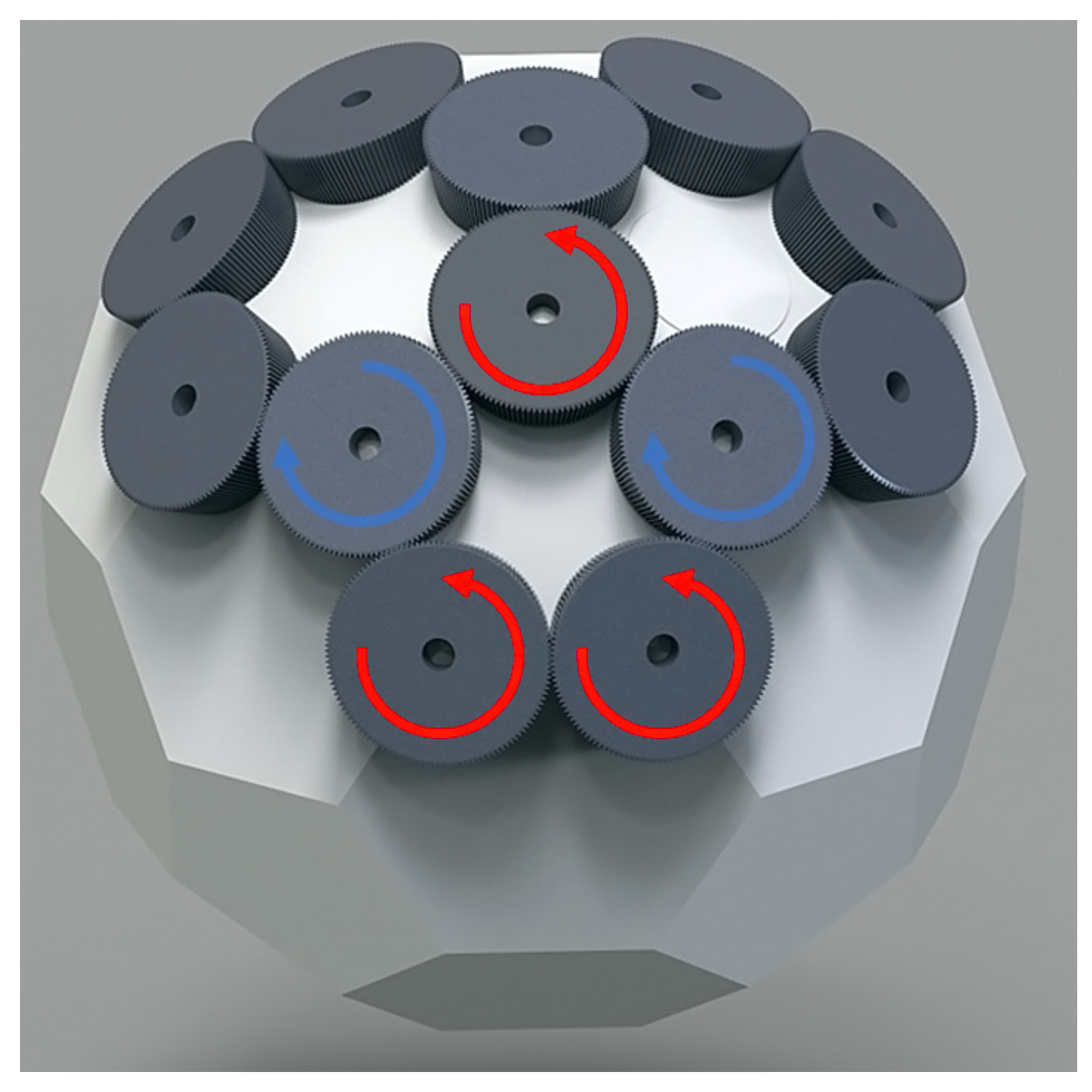
When choosing the gear type and arrangement, a few things need to be considered. First is the location of the gears. Their axes can coincide with the vertices of the polyhedron or can be placed in the center of each polygon face, or a combination of both. In either case the number of gears and their placement should not result in a closed loop of gears with an odd number of gears. This would result in two neighboring gears with the same direction of rotation and would make the working of the mechanism impossible, as shown in Figure 3.

Figure 3.
Gear interference caused by placing the gear axes on the vertices of an odd-sided polygon. Colored arrows indicate direction of rotation.
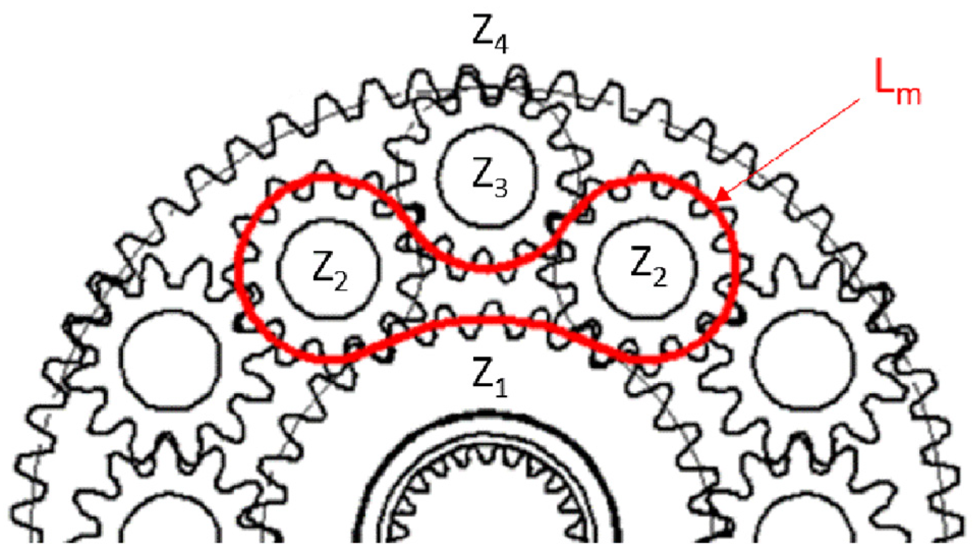
A polyhedron which consists of polygons with an even number of edges is better suited. Usually, straight bevel gears are used when they need to be arranged in a spherical pattern. The apex or gear cones coincide with the center of the circumscribed sphere of the chosen polyhedron. Furthermore, it is easier to meet the closed loop meshing conditions when a larger number of teeth are used, and the undercut or pointing of gears is avoided. Another simplification is to use integer numbers for edge lengths of the polyhedron and gear modules. Anyway, edge length and sphere size of choice can be achieved with the application of necessary tooth profile shifts. The assembly condition for closed loop gearing or constrained gear system states that the mesh path defined by the arcs of the reference diameters of the gears must divide to an integer number by pitch as shown in Figure 4.
where Lm is the length of the mesh path and m is the module of gear.

Figure 4.
Length of mesh path in constrained planetary gear system. z1—sun gear, z2—inner row planet gears, z3—outer row plant gears, z4—ring gear.
In the next sections two different gear mesh spheres will be modelled, each with a different polyhedron as a starting geometry, and a different gear arrangement.
2. Synthesis of Polyhedron-Based Gear Mesh Spheres
2.1. Truncated Cuboctahedron Gear Sphere
The first example is based on a truncated cuboctahedron [3]. It is a polyhedral that consists of 12 squares, 8 regular hexagons and 6 regular octagons, shown in Figure 5.
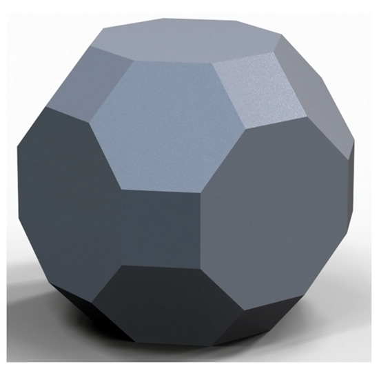
Figure 5.
Model of truncated cuboctahedron.
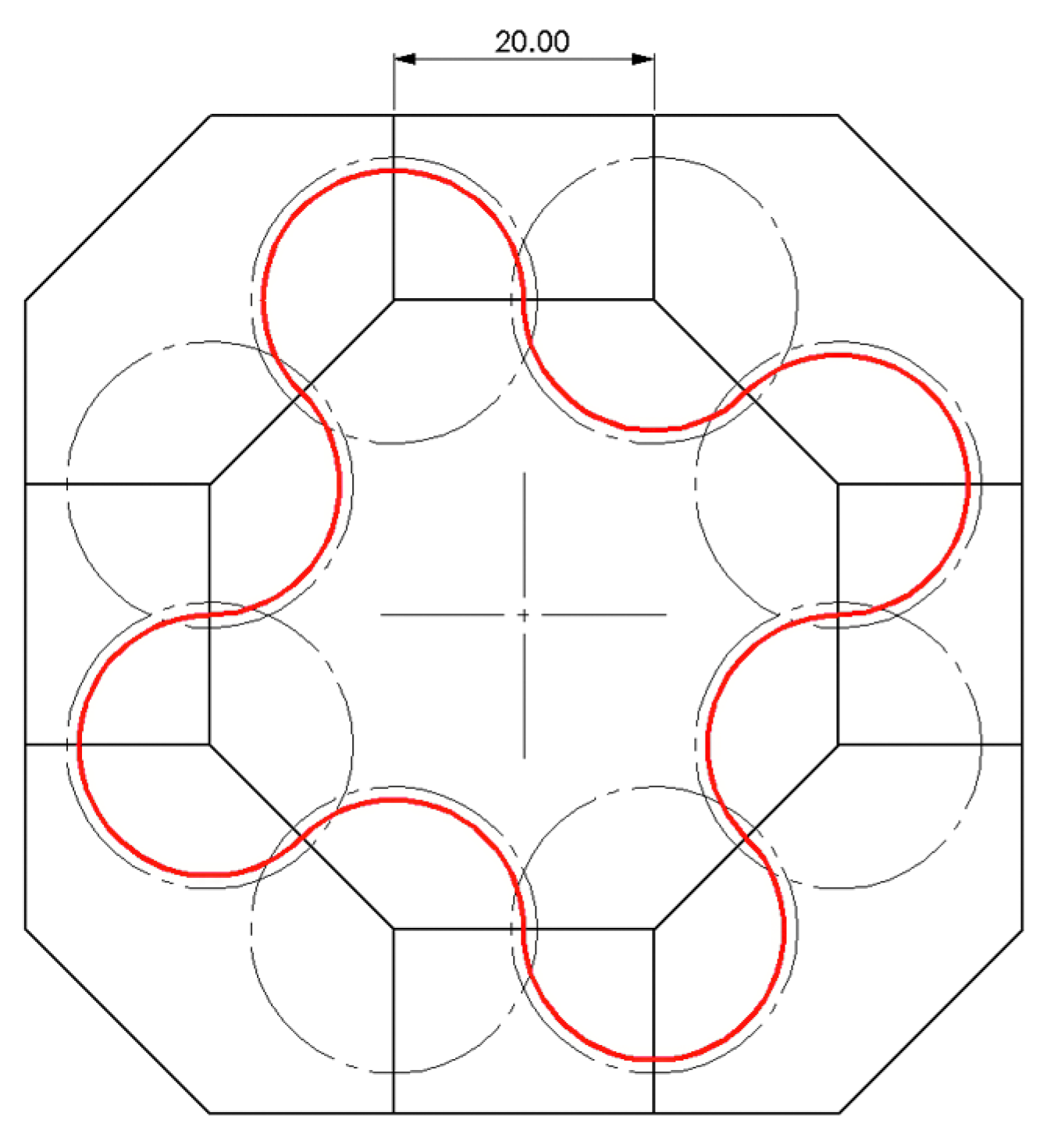
Because it consists of polygons with even sides, it is possible to locate gear axes on all its 48 vertices. To do that, the bevel gears must follow the rule described in Equation (1). One way to do that is to look at the problem in two dimensions and make a planar projection of the bevel gears. Or simply put, to make a two-dimensional closed gear loop for each of the polygons with spur gears placed on each of the edges. Then use this calculation to obtain the number of teeth that satisfies the condition and use the same number in the bevel gears. As previously stated, using an integer number for the sides of the polygon and the gear module simplifies the task. In this case a length of 20 mm for the side is chosen which also represents the center distance between the gears. For simplicity, module 1 is used for the gears, then the closed mesh path length for the polygons is calculated. From the results it can be seen that a gear with 20 teeth satisfies the conditions. An example of the mesh path for the octagon is presented in Figure 6.
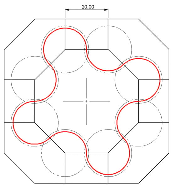
Figure 6.
Mesh path length for octagonal closed loop of gears.
After that the following equation can be used to determine the radius of the circumscribed sphere:
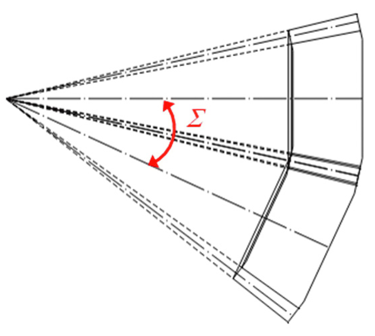
Using the chosen length of the side of the polygons and the radius of the sphere, an isosceles triangle can be constructed. Using trigonometry, the angle between the radiuses can be obtained which will be the same as the shaft angle-Σ (Figure 7) for the bevel gears since the radius of the sphere is the axis of the gear. In this case it is 24.92°.

Figure 7.
Shaft angle Σ for bevel gears.
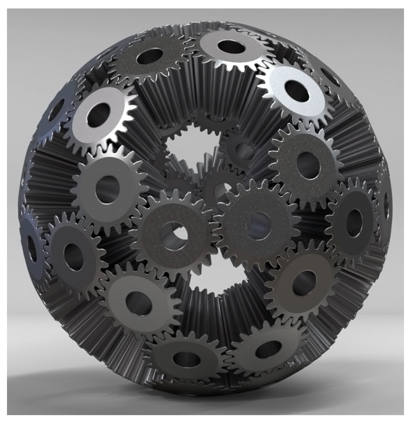
With knowledge of the shaft angle, number of teeth, module, and the gear width of choice, the full geometry of the bevel gears can be obtained. Information on the geometry of bevel gears can be found in numerous mechanical engineering and machine design books [4,5]. These parameters can also be input into gear modelling software so that a 3D model of the gears is obtained. With that done all that is left is to arrange the gears of the vertices of the polyhedral so that the pitch point of their axes coincides with the center of the sphere. The resulting model of the arrangement is shown in Figure 8.

Figure 8.
Truncated cuboctahedron gear sphere.
2.2. Truncated Icosidodecahedron Gear Sphere
A truncated icosidodecahedron is an Archimedean solid that consists of 30 squares, 20 regular hexagons and 12 regular decagons, shown in Figure 9. A good article on modelling such a figure can be found in [6].
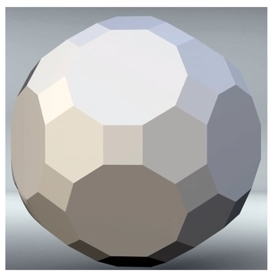
Figure 9.
Model of truncated icosidodecahedron.
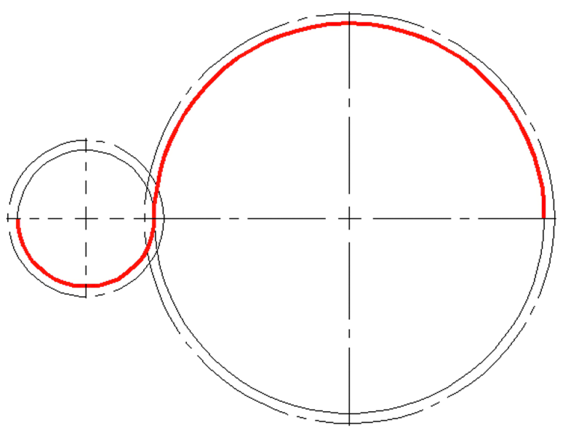
In this example the gears will be located on the faces of the polyhedron. Two different sized gears will be used. The large ones will be located on the decagon faces and the small ones on the square faces with the gear axes coinciding with the center of the polygons. So, the shaft angle is determined by these two axes. The angle between these two axes is the same as the inner dihedral angle between the square and the decagon, which is 31.72 degrees. The teeth matching conditions can be determined in similar manner as with the previous example with the truncated cuboctahedron. In a two-dimensional view the mesh path length defined by the reference diameters of the gears is shown in Figure 10 and again, it must divide evenly by pitch (π.m).

Figure 10.
Mesh path length for truncated icosidodecahedron.
Since each large gear is surrounded by five evenly spaced small ones, the number of the teeth of the large one should divide evenly by 5. To determine the size of the gears the inscribed circles of the square and decagon can be used as a guide for the reference diameters. Although strict following of the dimensions is not necessary if the shaft angle and mesh path conditions are satisfied, and the resulting pattern of gears does not result in neighbor interference. In this example instead of chosen side length, the circumscribed sphere radius will be used as a starting dimension. A value of 100 mm is used for rc. From this, the length of the edge of the polyhedron can be determined using this equation:
This results in an edge length of 26.299 mm. This will also be the diameter of the inscribed circle of the square faces and the reference diameter of the small bevel gear for the decagon faces. The radius of the inscribed circle Ri can be determined from the following equation:
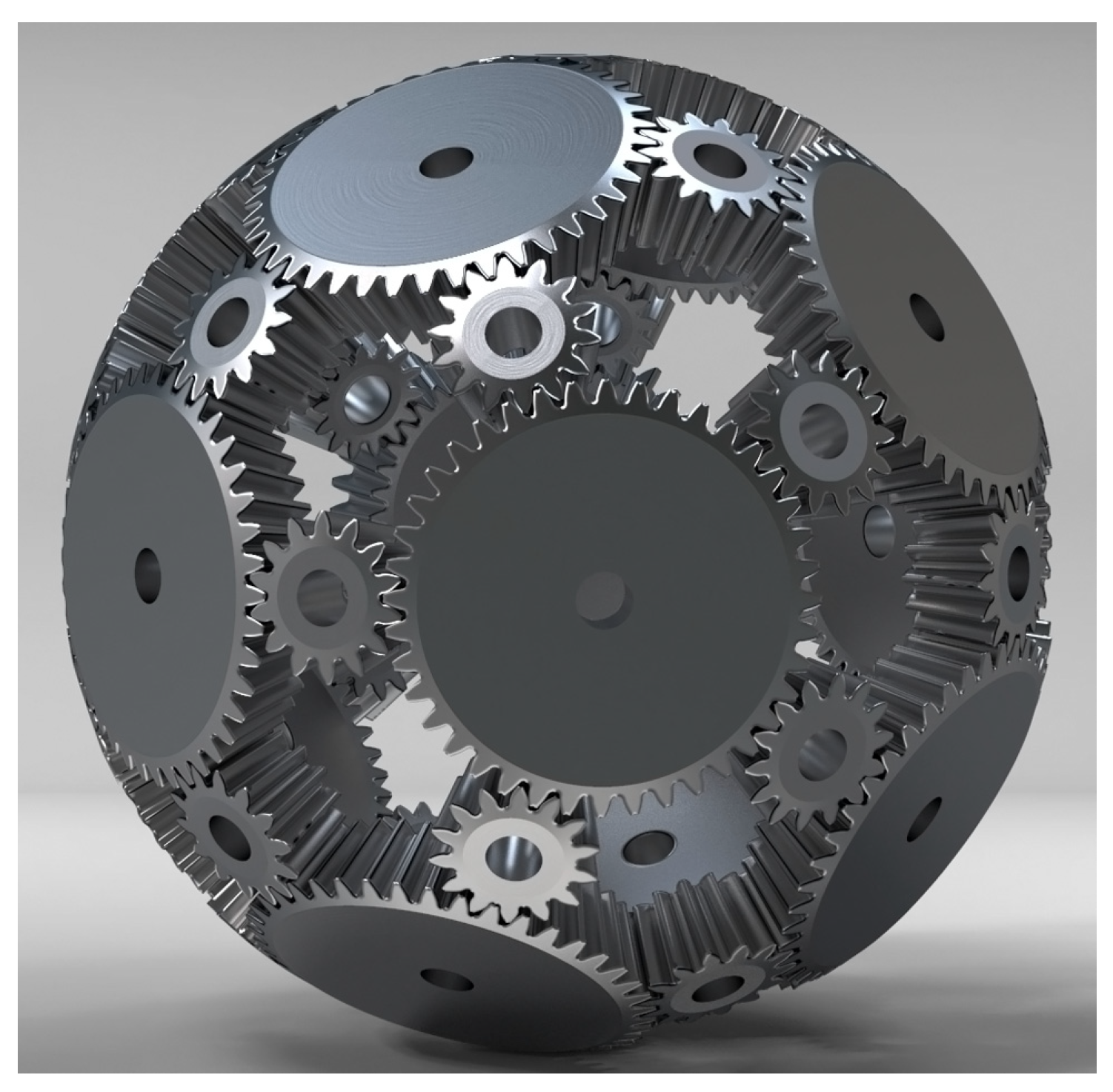
The result is 40.47 mm, which is the reference radius of the large bevel gear. It is not possible to use these values for reference diameters with standard gear modules. The closest that complies with all the specific conditions are 80 mm for the large gear and 28 for the small. Using module two, this results in 40 teeth in the large gear and 14 in the small gear. It should be noted that this will result in a slight deviation from the initially chosen radius of circumscribed sphere volume of the model. However, with custom modules and careful selection of gear profile shift coefficients, almost any exact numbers can be achieved. Like the previous example, from knowledge of the module, the number of teeth and the shaft angle, the full geometry of the bevel gears can be obtained. All that is left is to arrange the gears on the faces of the polyhedron. The resulting model is shown in Figure 11.
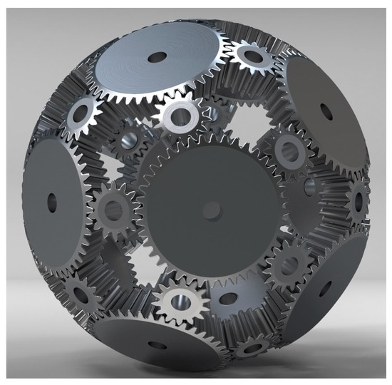
Figure 11.
Truncated icosidodecahedron gear sphere.
3. Conclusions
The presented specific conditions and approaches for synthesis of a spherical shaped gear arrangement resulted in the successful generation of two different models. However, these techniques are not limited to these examples only. Creating spherical or other shaped gear arrangements are possible with other polyhedrons and geometrical shapes, if the assembly and neighbor conditions are met.
Despite not performing as responsible and demanding tasks as transmissions in classical mechanical engineering, the gear mechanisms presented in the article and others that are similar have their own significant challenges. The implementation of such projects requires careful design and consideration of the specific requirements for the assembly and kinematics of the products. Synthesizing these complex and rarely encountered gear engagements can enhance the skills of designers working in the field of gear transmissions.
Author Contributions
Conceptualization and methodology, A.A. and V.I.; software, A.A.; investigation, A.A. and V.I.; resources, V.I.; writing and editing, A.A. and V.I.; visualization, A.A.; supervision, V.I. All authors have read and agreed to the published version of the manuscript.
Funding
This research was funded by the Research and Development Sector at the Technical University of Sofia, grant number 231ИП0019-06.
Institutional Review Board Statement
Not applicable.
Informed Consent Statement
Not applicable.
Data Availability Statement
The data presented in this study are available on request from the corresponding author. The data are not publicly available due to privacy restrictions.
Conflicts of Interest
The authors declare no conflicts of interest.
References
- Soto, H.; Bechthold, D. Tessellating the Sphere with Regular Polygons. Math. Teach. 2004, 97, 165–167. [Google Scholar] [CrossRef]
- De Hovitz, D.C. The Platonic Solids an Exploration of the Five Regular Polyhedra and the Symmetries of Three-Dimensional Space; 2016. Available online: https://www.whitman.edu/Documents/Academics/Mathematics/2016/DeHovitz.pdf (accessed on 10 August 2023).
- Rajpoot, H. Mathematical Analysis of Cuboctahedron; M.M.M. University of Technology: Gorakhpur, India, 2014. [Google Scholar]
- Jelaska, D.T. Gears and Gear Drives; John Wiley & Sons Ltd.: Hoboken, NJ, USA, 2012. [Google Scholar]
- Litvin, F. Gear Geometry and Applied Theory, 2nd ed.; Gear Load Sharing; Cambridge University Press: Cambridge, UK, 2004. [Google Scholar]
- Design & Build a Truncated Icosidodecahedron! Available online: https://www.instructables.com (accessed on 10 August 2023).


Disclaimer/Publisher’s Note: The statements, opinions and data contained in all publications are solely those of the individual author(s) and contributor(s) and not of MDPI and/or the editor(s). MDPI and/or the editor(s) disclaim responsibility for any injury to people or property resulting from any ideas, methods, instructions or products referred to in the content. |
© 2024 by the authors. Licensee MDPI, Basel, Switzerland. This article is an open access article distributed under the terms and conditions of the Creative Commons Attribution (CC BY) license (https://creativecommons.org/licenses/by/4.0/).