1. Introduction
Steel construction is experiencing significant global growth. In addition to enhancing cost-effectiveness, construction speed, and quality, professionals are actively involved in the development of environmentally sustainable and green steel buildings, across their entire lifecycle. In general, steel is an expensive material when compared to the alternatives, but over the lifespan of a structure, it demonstrates its affordability through significant cost savings. Cold-formed steel is becoming more popular due to its light weight and cost-saving benefits.
Due to their exceptional strength-to-weight ratio and simplicity in construction, structural members made from cold-formed steel can result in a more cost-effective design than those using hot-rolled steel members. Cold-formed steel (CFS) is remarkably long-lasting and durable and may be recycled endlessly. Repurposing CFS for building restorations provides a sustainable and environmentally responsible choice. Construction projects may be completed more quickly using CFS, while adhering to green building guidelines and regulations. CFS improves the energy efficiency of buildings, promoting ecologically friendly and sustainable building methods. In steel-framed homes and commercial structures, light-gauge CFS sections are frequently employed as members for roof trusses. Many studies have concentrated on cold-formed steel open sections with various edge stiffeners, and different arrangements of plain and lipped channels. Stiffeners effectively disperse axial loads, enhance overall stability, and postpone the beginning of local and overall buckling when used on the flanges or webs of these columns. As a result, the structural integrity and load-bearing capacity of CFS columns are increased. Young (2008) carried out an investigation of CFS built-up closed sections with intermediate stiffeners. Investigations on the strength and behavior of cold-formed steel columns were performed both experimentally and numerically. The column strengths determined in their research was contrasted with the design strengths found in CFS buildings, which were determined using a variety of international standards. There are different calculation processes for stainless, high-strength, and carbon steel axially compressed cold-formed profiles. The current trends in this discipline are shown in the results of authors who have published their work in international publications. A computational and experimental examination of cold-formed, centrally compressed components is also presented in [
1,
2,
3,
4,
5].
Significant research has been carried out on CFS lipped columns and columns using back-to-back plain angles. These studies aimed to explore the effect of local bucking and global buckling, to give design guidance for CFS angle columns [
6,
7,
8,
9].
Chen (2007) and Gunalan (2014) used finite element analysis to examine the behavior of CFS columns with a lipped channel cross-section at high temperatures. The failure loads and load-shortening curves of lipped channel columns were examined, which gave a general guideline about the behavior of CFS lipped channel columns [
10,
11].
In the investigation by Anbarasu (2019), the finite element code ABAQUS was employed to create a numerical model. Geometric and material nonlinearity was included in the finite element models. In their finite element modeling, the impacts of the initial local and general geometric flaws were taken into account [
12]. This provided a general guideline on the finite element modelling aspect when using ABAQUS. Many studies have been carried out by Zhang and Young on closed-section cold-formed steel columns with web stiffeners. Built-up closed sections were made using high-strength steel plate with varying thicknesses and column lengths. Web stiffeners were introduced and their effect was studied for different boundary conditions [
13,
14,
15,
16,
17,
18].
Four distinct cross-sectional geometries for built-up cold-formed steel columns were studied by Meza et al. (2020). Individual channels and flat plates with nominal thicknesses ranging from 1.2 mm to 2.4 mm were used to create built-up sections, which were then joined using either bolts or self-drilling screws [
19]. It was observed in a study by Roy et al. (2019) that the design strength can overestimate the capacity of built-up columns that are subject to local buckling failure, but this is often 15% more conservative [
20].
2. Materials and Methods
In this investigation, V-shaped web stiffeners were added to enhance the web’s strength through preventing distortional and local buckling.
The ultimate strength of cold-formed steel stud columns with holes under axial compression was predicted through the effective width method using Equation (1)
where P
M = ultimate strength of the cold-formed stud column; A
net is the net cross-sectional area; fy = yield strength; Ae is the effective cross-sectional area, which can be predicted by calculating the effective width of the cross section, as given in Equation (2).
where bc is the breadth of the plate’s crushed zone, b is the width of the plate, and t is the thickness of the plate. For the CFS axis and stud columns, bc = b, α =1, and ρ = (235 k1k/φfy), where k1 is the plate’s interaction buckling coefficient, taking the influence of the holes into account.
2.1. Details of Specimen Cast:
Table 1 Shows the Section Details of Specimen achieved as per IS 801 [
21] and BS 5950 Part-5 [
22] and Cast.
2.2. Bolt Calculation
Section 100 × 40 × 15 × 2.0
Number of bolts
Factored load/strength of bolt in joints = 93.53/5.90 = 14 bolts
Table 2 shows the connection details of the specimen.
High-strength MS250 steel sheets having a yield stress of 250 MPa were used to fabricate the CFS specimens, which were then brake-pressed.
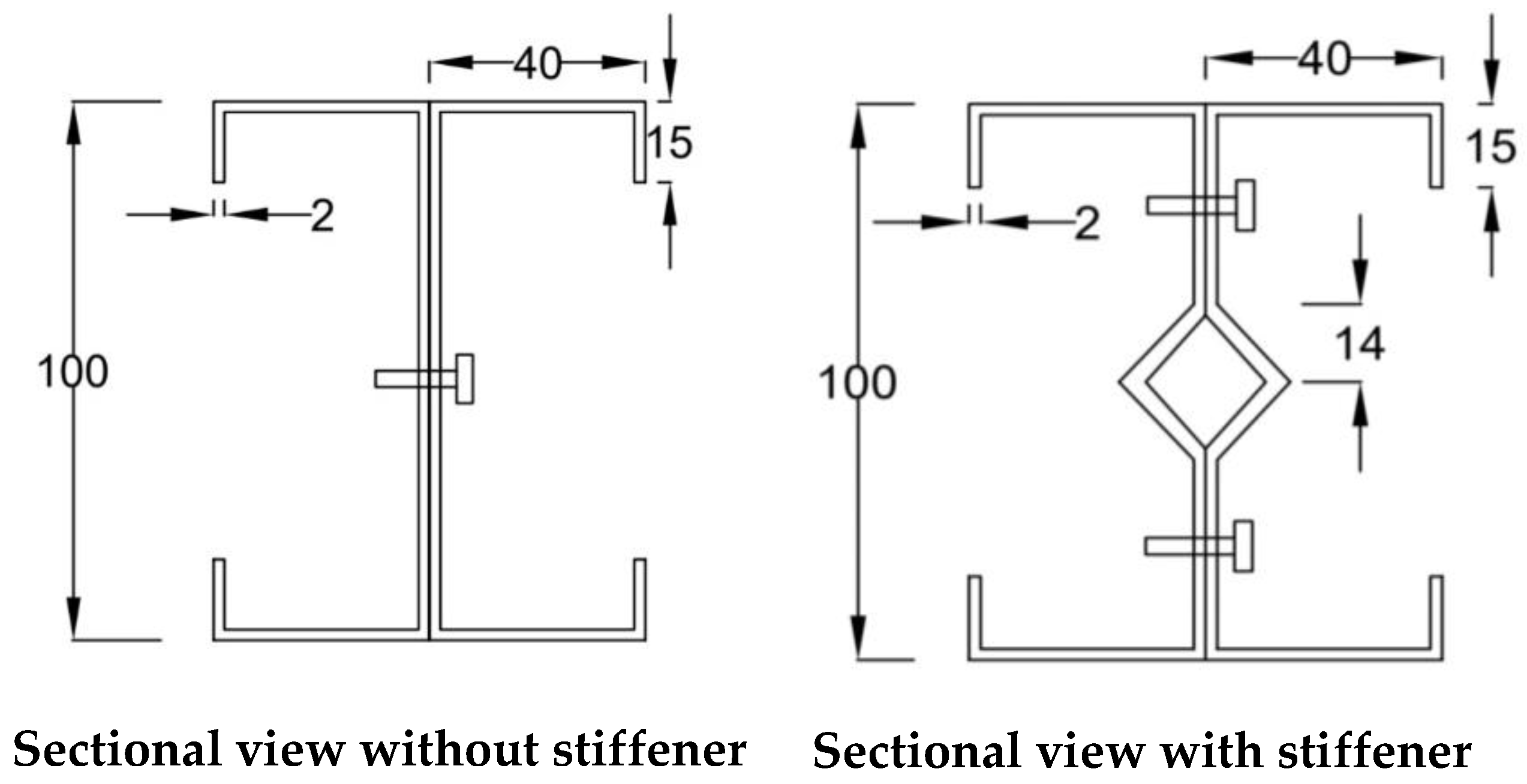
Figure 1 illustrates a cross-section of the specimens used in the experimental study. Specimen 1 was made through casting with a normal back-to-back channel section with a nominal web width of 100 mm and a nominal thickness of 2 mm. Specimen 2 was made by joining two channels back-to-back, and the stiffener position was created by bending the ineffective section of web to strengthen the column. For both lipped channels, the lip’s nominal width was 15 mm, the flange width was 40 mm, and the height of both columns was 1230 mm.
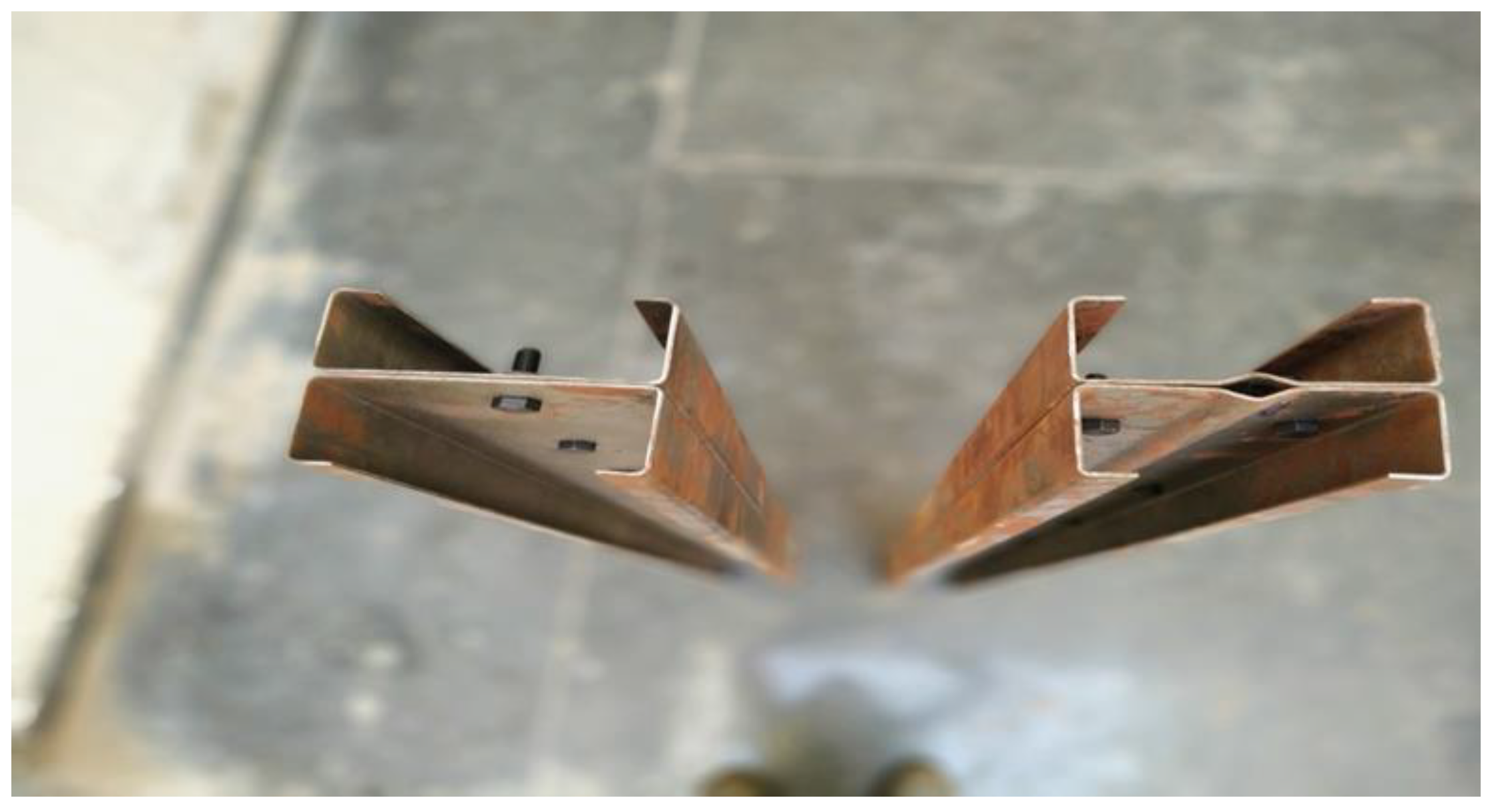
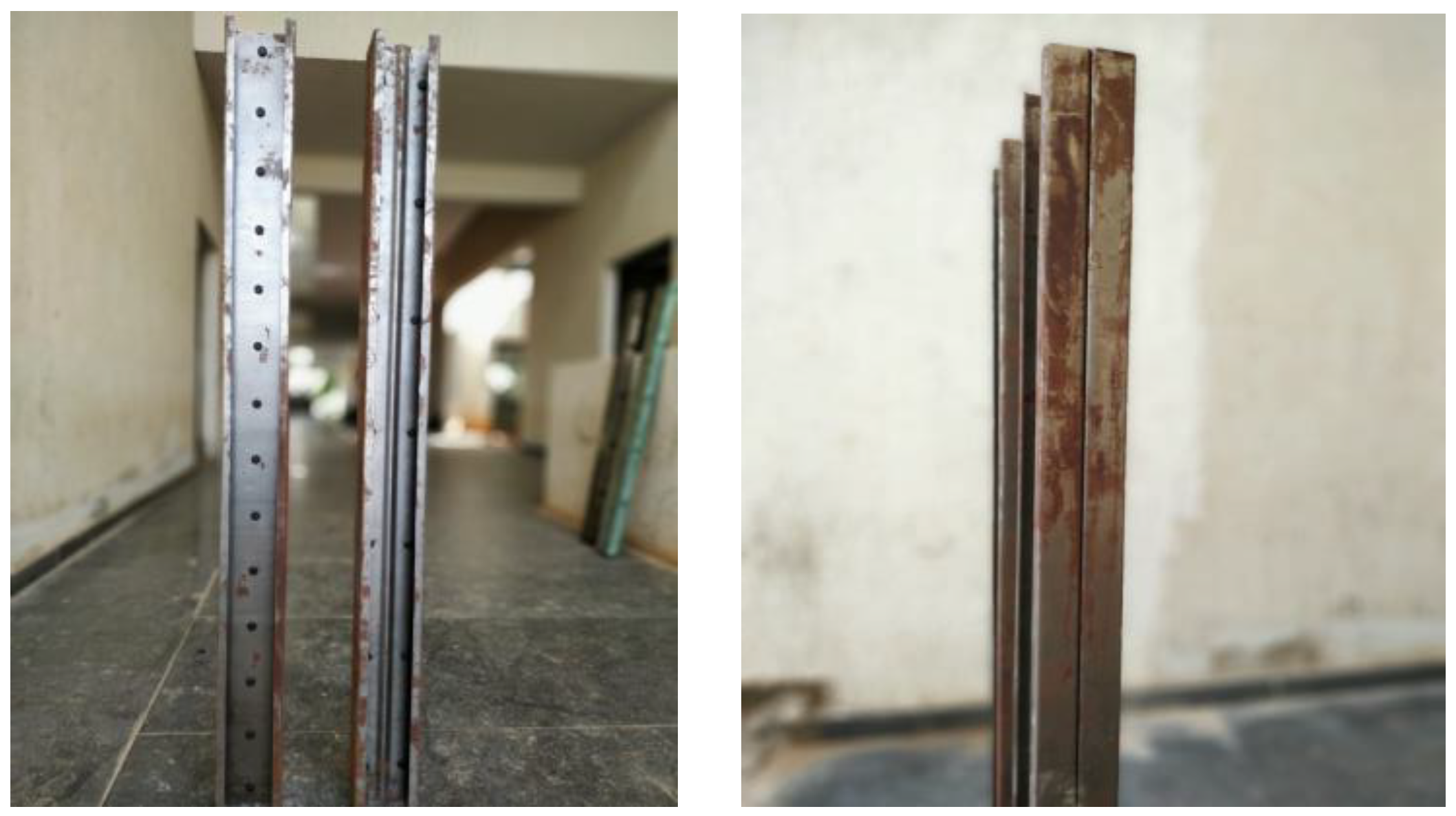
Figure 2 and
Figure 3 show a top view and elevation view of the specimen cast.
Table 3 shows the properties of the cold-formed steel section for the experimental test.
2.3. Experimental Setup
The compression test was carried out on a loading frame with a 100-ton capacity. Rubber gaskets were inserted between the base plate and the loading platens, to replicate hinged-end conditions at both supports. A hydraulic jack was used to apply a load axially. LVDT and dial gauges were used to measure the readings.
Figure 4 displays the test specimen securely positioned within the loading frame.
The alignment was verified and deflection gauges were affixed at the required positions. Load cells were positioned between the proving ring and the support. A gradual axial load was applied using a hydraulic jack, and essential measurements were taken from the proving ring and deflection gauges. Graphs were generated based on the acquired results. Theoretical calculations (as per codes and from the literature) were performed and compared with the experimental results. The experimental results were contrasted with the numerical data generated through an ANSYS finite element model.
3. Finite Element Modelling
This research utilized the finite element analysis software ANSYS to create models for the specimens under investigation. These models were employed to assess the ultimate loads and overall deformations of steel columns under simply supported end conditions, both with and without web stiffeners, in comparison to the experimental results.
3.1. Element Types
Table 4 provides an overview of the element types used in this model. Shell elements, such as SHELL181 (as illustrated in
Figure 5), are commonly employed for modeling thin-walled structures, delivering accurate results within a reasonable time frame when compared to volume elements. The ANSYS element library includes several shell elements, like SHELL43 and SHELL93, each offering features tailored for the effective representation of thin-walled structures. SHELL181 is well-suited for analyzing structures ranging from thin to moderately thick shells, making it suitable for linear, large rotation, and/or large strain nonlinear applications. Loads are applied using load-bearing plates.
Among the various element types available, SOLID45 stands out as one of the most suitable options. Other elements such as SOLID46, SOLID65, and SOLID70 are also available, but SOLID45 offers a range of capabilities including plasticity, creep, swelling, stress stiffening, large deflection, and large strain capabilities.
3.2. Material Properties
The experimental test results were used as input data within ANSYS to define the steel properties. To ascertain the modulus of elasticity and yield strength of the cold-formed steel, coupon tests were conducted. Additionally, compression tests were carried out to ascertain the material’s stress and strain properties. The resulting values from these tests can be found in
Table 5.
3.3. Modelling
Upon defining suitable material properties, a model was constructed using the graphical user interface.
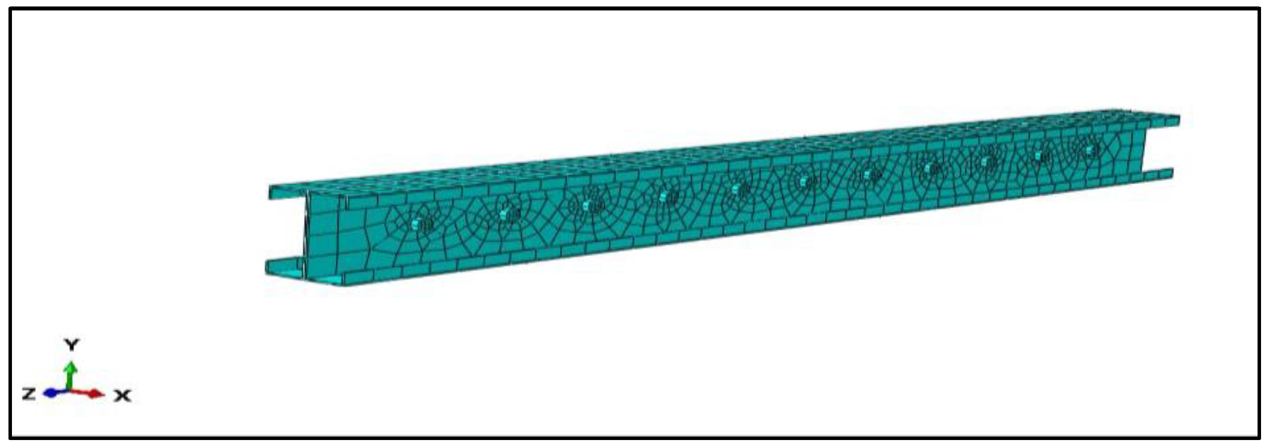
Figure 6 illustrates the meshing of the modeled column. A variable density mesh was created using the mapped meshing technique. A fine mesh was applied in the vicinity of the perforations, while a coarser mesh was used further away from them.
Figure 6 depicts the element mesh generated for the p2-wnf model, showcasing the distinct regions of the mesh in detail.
3.4. Loading
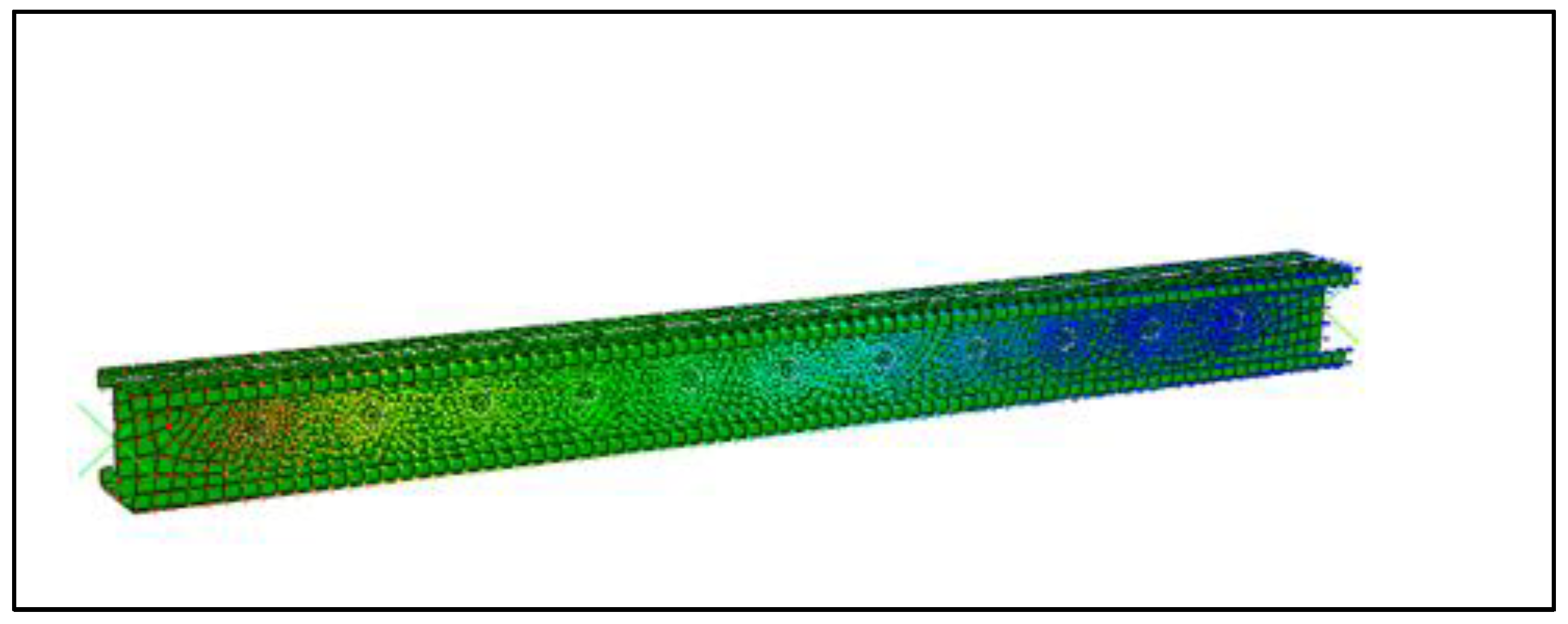
The force “p” was applied along the central axis of the column. At each node on the plate, the applied force was distributed as one-tenth of the total force. The stress results can be observed in
Figure 7.
4. Result and Discussion
4.1. Experimental Results
Figure 8 shows the stress–strain curve obtained from experimental testing on the back-to-back channel specimen with and without stiffeners. From the nonlinear stress–strain curve behavior in the cold-formed steel columns, it is observed that when subjecting the cold-formed steel columns to an increasing amount of stress (load), the relationship between stress and strain was not linear. In addition, when more stress was applied to the material, it did not respond with a proportional increase in strain (deformation). Instead, the material exhibited a nonlinear response. This behavior is seen in the stress–strain curve in
Figure 8a. The strain hardening resulted from the cold-forming process, which reinforced the material. The influence was more noticeable in the stainless-steel sections than in the regular carbon-steel sections, due to the high ratio of ultimate to yield strength and the shape of the stress–strain curve. Furthermore, due to the application of solely axial force and the presence of stiffeners, distortional buckling and local buckling were not observed. The experimental results show that in the columns with stiffener, there was a decrease in strain by 27.4% compared to that of the normal columns without stiffener.
Figure 8b shows the load vs. strain graph from the experimental testing. From the graph, it can be observed that specimens with stiffener showed a linear pattern up to a load of 88 kN, after which they started deflecting.
4.2. Validation in Experimental and Numerical Results
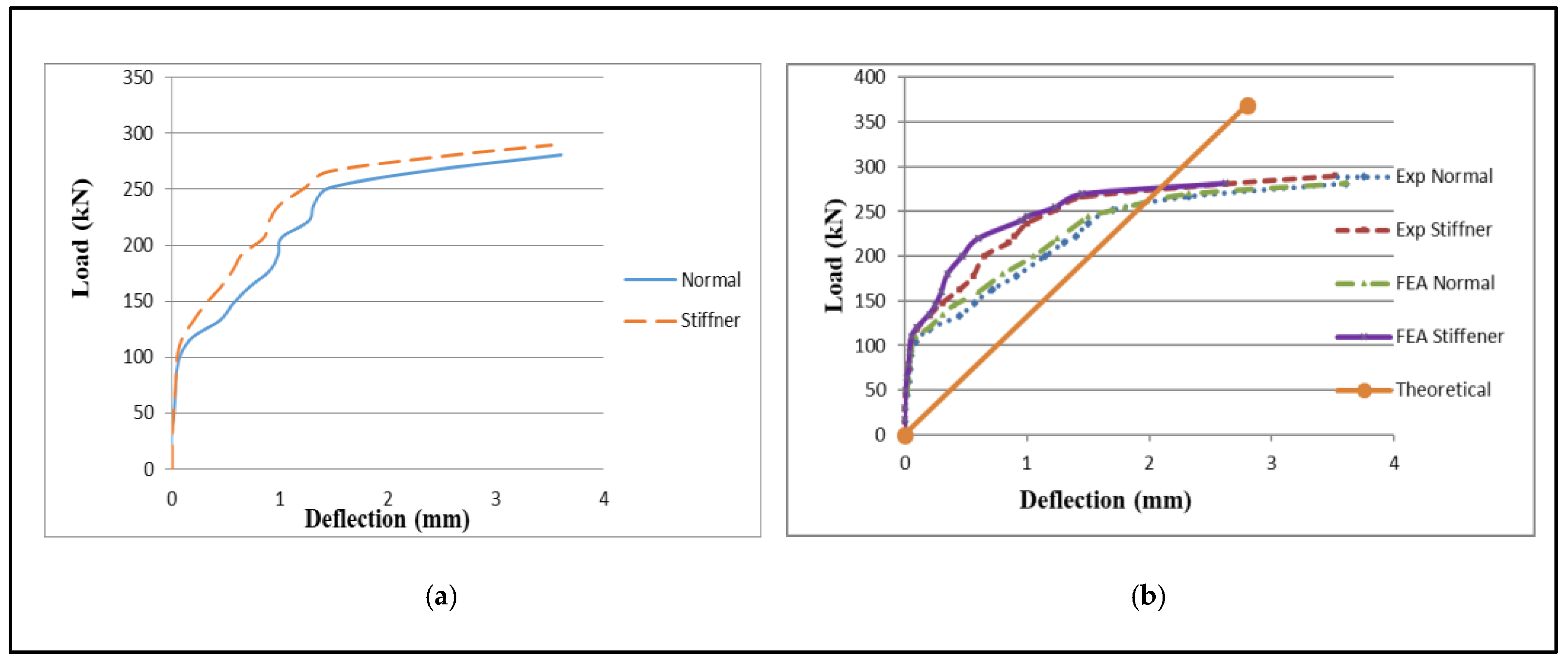
Figure 9a shows a load vs. deflection graph from the experimental and numerical analysis, along with literature and theoretical validations.
Figure 9b shows the load deflection curves of the tested specimens. The experimental results show that the stiffened columns deflected 29.43% less than the normal columns. This proved that the V-shaped stiffener was effective in improving the structural integrity of the column.
The numerical results showed that the stiffened column deflected 32% less than the normal column. This proved that the intermediate stiffener improved the structural integrity of the column, and an efficient cross-sectional arrangement was finally developed that boosted the strength of the specimen by 32%. This falls in line with the literature [
1,
2,
3,
4,
5]. Instead of more material being introduced into the specimen, efficient use of the material produced this noticeable improvement.
This study additionally confirmed the accuracy of the ANSYS shell finite element model through comparing it to the experimental results. The numerical outcomes achieved in this research exhibited a reasonably close alignment with the experimental values for laterally unconstrained columns. Further parametric studies could be performed with the available finite element modelling. The nonlinear stress–strain behavior observed in cold-formed steel columns opens the door for parametric studies and the development of more efficient column sections. By systematically exploring variables like material properties, cross-sectional dimensions, position of stiffeners, spacing of bolts at different intervals and with various screw diameters, and loading conditions, more effective sections could be achieved. This research fosters innovation, offering tailored solutions that maximize the potential of cold-formed steel in various construction applications.
5. Conclusions
This study involved both experimental and numerical examinations of cold-formed steel built-up sections with intermediate stiffeners. The test specimens were fabricated using high-strength zinc-coated grade steel with a nominal yield stress of 240 N/mm2.
Tensile coupon testing was employed to determine the material properties of the cold-formed steel specimens. The columns with pinned ends were tested at specified lengths, and the observed failure modes included local buckling and distortional buckling of the webs.
The test strength was compared with an advanced numerical model developed using FEM, it was also compared with the designed strengths obtained using theoretical values.
The experimental results showed that the column with stiffener decreased the strain by 27.4% compared to that of the normal column without stiffener.
The experimental results showed that the stiffened columns deflected 29.43% less than the normal column. This proved that the V-shaped stiffener was effective in improving the structural integrity of the column.
The numerical result showed that the stiffened column deflected 32% less than the normal column. This proved that the intermediate stiffener improved the structural integrity of the column.
From the comparison of the experimental and ANSYS results, a variation of less than 15% was observed in all cases, which is within the permissible limit.
From the results of the comparisons, the ultimate load obtained from the FEM was slightly higher than the experimental ultimate load, and the design strength calculated from the required code was conservative compared with the experimental ultimate load.
Author Contributions
Conceptualization: P.P. and K.K.; Methodology: A.R.J. and R.S.; Software, A.R.J. and R.S.; Formal analysis: A.R.J. and R.S.; Writing—original draft preparation, A.R.J. and R.S; Writing—review and editing, P.P. and K.K. All authors have read and agreed to the published version of the manuscript.
Funding
This research received no external funding.
Institutional Review Board Statement
Not applicable.
Informed Consent Statement
Not applicable.
Data Availability Statement
Will be made available on request.
Conflicts of Interest
The authors declare no conflict of interest.
References
- Young, B. Research on cold-formed steel columns. Thin-Walled Struct. 2008, 46, 731–740. [Google Scholar] [CrossRef]
- Davies, J. Recent research advances in cold-formed steel structures. J. Constr. Steel Res. 2000, 55, 267–288. [Google Scholar] [CrossRef]
- Bešević, M.; Prokić, A.; Landović, A.; Kasaš, K. The Analysis of Bearing Capacity of Axially Compressed Cold Formed Steel Members. Thin-Walled Struct. 2016, 61, 88–97. [Google Scholar]
- Liu, D.; Liu, H.; Chen, Z.; Liao, X. Structural behavior of extreme thick-walled cold-formed square steel columns. J. Constr. Steel Res. 2017, 128, 371–379. [Google Scholar] [CrossRef]
- Quach, W.M.; Teng, J.G.; Chung, K.F. Effect of the manufacturing process on the behaviour of press-braked thin-walled steel columns. Thin-Walled Struct. 2010, 32, 3501–3515. [Google Scholar] [CrossRef]
- Shifferaw, Y.; Schafer, B.W. Cold-formed steel lipped and plain angle columns with fixed ends. Thin-Walled Struct. 2014, 80, 142–152. [Google Scholar] [CrossRef]
- Young, B.; Ellobody, E. Buckling Analysis of Cold-Formed Steel Lipped Angle Columns. J. Struct. Eng. 2005, 131, 1570–1579. [Google Scholar] [CrossRef]
- Gunalan, S.; Mahendran, M. Improved design rules for fixed ended cold-formed steel columns subject to flexural–torsional buckling. Thin-Walled Struct. 2013, 73, 1–17. [Google Scholar] [CrossRef]
- Young, B.; Chen, J. Column tests of cold-formed steel non-symmetric lipped angle sections. J. Constr. Steel Res. 2008, 64, 808–815. [Google Scholar] [CrossRef]
- Chen, J.; Young, B. Cold-formed steel lipped channel columns at elevated temperatures. Eng. Struct. 2007, 29, 2445–2456. [Google Scholar] [CrossRef]
- Gunalan, S.; Mahendran, M. Experimental and numerical studies of fire exposed lipped channel columns subject to distortional buckling. Fire Saf. J. 2014, 70, 34–45. [Google Scholar] [CrossRef]
- Anbarasu, M. Numerical investigation on behaviour and design of cold-formed steel built-up column composed of lipped sigma channels. Adv. Struct. Eng. 2019, 22, 1817–1829. [Google Scholar] [CrossRef]
- Zhang, J.-H.; Young, B. Experimental investigation of cold-formed steel built-up closed section columns with web stiffeners. J. Constr. Steel Res. 2018, 147, 380–392. [Google Scholar] [CrossRef]
- Zhang, J.-H.; Young, B. Compression tests of cold-formed steel I-shaped open sections with edge and web stiffeners. Thin-Walled Struct. 2012, 52, 1–11. [Google Scholar] [CrossRef]
- Zhang, J.-H.; Young, B. Finite element analysis and design of cold-formed steel built-up closed section columns with web stiffeners. Thin-Walled Struct. 2018, 131, 223–237. [Google Scholar] [CrossRef]
- Meza, F.J.; Becque, J.; Hajirasouliha, I. Experimental study of cold-formed steel built-up columns. Thin-Walled Struct. 2020, 149, 106291. [Google Scholar] [CrossRef]
- Young, B. Design of channel columns with inclined edge stiffeners. J. Constr. Steel Res. 2004, 60, 183–197. [Google Scholar] [CrossRef]
- Yan, J.; Young, B. Column Tests of Cold-Formed Steel Channels with Complex Stiffeners. J. Struct. Eng. 2002, 128, 737–745. [Google Scholar] [CrossRef]
- Meza, F.J.; Becque, J.; Hajirasouliha, I. Experimental study of the cross-sectional capacity of cold-formed steel built-up columns. Thin-Walled Struct. 2020, 155, 106958. [Google Scholar] [CrossRef]
- Roy, K.; Ting, T.C.H.; Lau, H.H.; Lim, J.B.P. Experimental Investigation into the Behaviour of CFS Built-Up Channels Subjected to Axial Compression. In Advances in Transportation Engineering; Springer: Singapore, 2019; pp. 89–105. [Google Scholar]
- IS 801; Code of Practice for Use of Cold Formed Light Gauge Steel Structural Members in General Building Construction. Bureau of Indian Standards: New Delhi, India, 1975.
- BS 5950-5; Structural Use of Steelwork in Building Part 5: Code of Practice for Design of Cold Formed Thin Gauge Sections. BSI: London, UK, 1998.
| Disclaimer/Publisher’s Note: The statements, opinions and data contained in all publications are solely those of the individual author(s) and contributor(s) and not of MDPI and/or the editor(s). MDPI and/or the editor(s) disclaim responsibility for any injury to people or property resulting from any ideas, methods, instructions or products referred to in the content. |
© 2024 by the authors. Licensee MDPI, Basel, Switzerland. This article is an open access article distributed under the terms and conditions of the Creative Commons Attribution (CC BY) license (https://creativecommons.org/licenses/by/4.0/).


 ,
, 


