Abstract
The objective of this research is to develop a suitable chassis dynamometer to test new vehicles for compliance with emission standards for type-approval in Pakistan. There is a lack of facilities and protocols for testing new passenger vehicles to measure vehicle exhaust gas emissions. This study is performed to fill this gap and might help local authorities in the implementation of exhaust emission test procedures. Assessment of exhaust emissions can be performed by placing the vehicle over the chassis dynamometer. An air-cooled eddy current dynamometer is selected for this purpose. The road load equation is used to simulate the real-life performance of a vehicle while driving at different speeds.
1. Introduction
Pakistan currently has emission standards of Tiers Pak-II that are equivalent to standards of EURO 2. The measuring method for Tier Pak-II is the New European Driving Cycles (NEDC). Therefore, it is the latest technology recently adopted by automobile manufacturers in Pakistan. Now, it is mandatory for all automobile manufacturers in Pakistan to follow the emission standards. However, the problem is that there is no independent approval authority within Pakistan that can offer testing services to vehicle manufacturers to make sure that the specific emission standards are met. Table 1 (first two columns) shows the specifications shared by one of the leading manufacturers in Pakistan, in which the emission standards followed by the manufacturer can be seen clearly. However, on the other hand, any CO2 emission data in compliance with EURO-II cannot be seen.

Table 1.
Technical specifications of passenger cars manufactured in Pakistan (first two columns) and other important parameters of various vehicles manufactured in Pakistan (last five columns).
Researchers are performing experimental and numerical investigations on a chassis dynamometer design. Lourenco et al. [1] proposed a model for a vehicle and twin roller chassis dynamometer to improve mobility systems. Zhang et al. [2] enclosed the latest research (on vehicle chassis dynamometer development) in a review article and proposed the AC chassis dynamometer as a mainstream trend. Different measurement aspects, road simulation, and control systems are also discussed.
This research is targeted to design a chassis dynamometer for type-approval of new passenger vehicles manufactured in Pakistan underneath environmental legislations in force. This chassis dynamometer could be used as a test platform for direct performance testing of new passenger vehicles in the laboratory. Another feature of this study is to obtain insight into the real-world emissions behavior of road vehicles in varying operating situations. Exhaust emissions are analyzed by a vehicle driving on the chassis dynamometer inside the modern emission testing laboratory (SGS Pakistan Pvt. Ltd.) at Karachi to verify the fitness of the vehicle in terms of pollutant emissions. Initially, roller design calculations are performed using numerical design tools. Then, the structure of the chassis dynamometer is designed for the power absorption from the chassis dynamometer at the time of the emission test.
2. Materials and Methods
2.1. Design of Chassis Dynamometer
The vehicle behavior under different road conditions is described by the road load equation (RLE). This RLE (Equation (1)) is a fundamental requirement of a chassis dynamometer. In order to simulate the real-life performance of a vehicle, RLE is used to calculate the change in torque with the change in vehicle speed. Its primary importance is that it provides a linkage between performance on the road and performance in the test cell.
where is the resistance to progress (N), V is the vehicle speed (km/h), a is the value equivalent to rolling resistance (N), b is the value equivalent to frictional resistance N/(km/h), c is the value equivalent to the coefficient of air resistance N/(km/h)2, M is the mass of the vehicle (kg), and θ is the road slope in radians.
Power required at any vehicle speed is shown in Equation (2) [3]:
First, there is the need to conduct an elementary survey of vehicle specifications manufactured in Pakistan. In this context, Table 1 (last five columns) presents power and some other performance parameters for many light-duty cars manufactured in Pakistan.
2.2. Components Selection
Detailed information regarding the selection of the dynamometer, transmission shafts, and roller design is included in Table 2. Figure 1a shows the position of front and rear rollers with maximum and minimum angles of tires, and Figure 1b shows the isometric view of rollers and shaft with designed dimensions.
Table 2.
Important final designed specifications of chassis dynamometer.
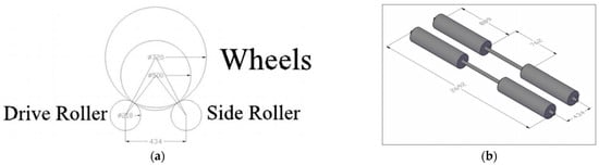
Figure 1.
(a) Position of front and rear rollers with maximum and minimum angles of tires. (b) Isometric view of rollers and shaft with designed dimensions.
A wheel’s rpm (N) is calculated by using Equation (3) [3], where R is the tire radius.
As in this research, the design of the chassis dynamometer is for a European type-approval test in which the maximum vehicle speed is 120 km/h, but to incorporate some tolerances, a 140 km/h maximum is considered. To calculate roller rpm, Equation (4) is used [3]:
where N1 and N2 are the rpms of the tire and roller, and D1 and D2 are the diameters of the tire and roller. For rollers (having 889 mm face length), a mild steel schedule 40 pipe is employed.
3. Results and Discussion
The final designed specifications of the chassis dynamometer are enclosed in Table 2. This test platform will be able to measure exhaust emissions when integrated with emission testing equipment. It will be the first step in testing the performance and ensuring the emission limits of new passenger cars manufactured in Pakistan.
As per NEDC, the complete testing requires around 20 min if performed without any interruption. NEDC consists of two segments. In the first segment, the vehicle under testing is driven through an urban driving cycle (ECE), which is completed four times. Every ECE comprises 15 phases. In the second segment, one extra-urban driving cycle (EUDC) is completed, which comprises 13 phases. Table 3 encloses the sample testing data for gaseous pollutants and the EUDC gear shift breakdown summary.
Table 3.
Sample testing data for gaseous pollutants and EUDC gear shift breakdown summary.
4. Conclusions
This study is focused on the design of a chassis dynamometer facility for European type-approval of new passenger vehicles manufactured in Pakistan. Exhaust emissions examination can be performed by putting the vehicle over this chassis dynamometer. For this purpose, an air-cooled eddy current dynamometer from Mustang having a maximum load absorption capability of 250 hp is selected, and RLE is used to simulate the real-time performance of a vehicle while driving at varying speeds.
Author Contributions
Conceptualization; K.U. and M.K.; methodology; M.H.; software; A.-B.S.; validation; H.A., M.A. and M.H.; formal analysis; M.A.; investigation; K.U.; writing; K.U. and M.H.; supervision.; M.K. All authors have read and agreed to the published version of the manuscript.
Funding
This research received no external funding.
Institutional Review Board Statement
Not applicable.
Informed Consent Statement
Not applicable.
Data Availability Statement
Not applicable.
Conflicts of Interest
The authors declare no conflict of interest.
References
- de Menezes Lourenço, M.A.; Eckert, J.J.; Silva, F.L.; Santiciolli, F.M.; Silva, L.C.A. Vehicle and Twin-Roller Chassis Dynamometer Model Considering Slip Tire Interactions. Mech. Based Des. Struct. Mach. 2022, 51, 6166–6183. [Google Scholar] [CrossRef]
- Zhang, X.; Zhou, Z. Research on Development of Vehicle Chassis Dynamometer. J. Phys. Conf. Ser. 2020, 1626, 012150. [Google Scholar] [CrossRef]
- Martyr, A.J.; Plint, M.A. Engine Testing: Theory and Practice; Elsevier: Amsterdam, The Netherlands, 2011. [Google Scholar]
Disclaimer/Publisher’s Note: The statements, opinions and data contained in all publications are solely those of the individual author(s) and contributor(s) and not of MDPI and/or the editor(s). MDPI and/or the editor(s) disclaim responsibility for any injury to people or property resulting from any ideas, methods, instructions or products referred to in the content. |
© 2023 by the authors. Licensee MDPI, Basel, Switzerland. This article is an open access article distributed under the terms and conditions of the Creative Commons Attribution (CC BY) license (https://creativecommons.org/licenses/by/4.0/).