1. Introduction
Aluminum, a lightweight and durable material, has become increasingly popular in the construction industry due to its numerous benefits [
1,
2]. Its inherent properties, such as a high strength-to-weight ratio, corrosion resistance, and recyclability, make it an ideal choice for various construction applications. The use of sheet aluminum, in particular, has seen a significant rise. Sheet aluminum is versatile and can be easily formed into various shapes making it suitable for a wide range of applications in construction, from roofing and cladding to interior design. Its malleability allows for the creation of unique and complex designs, contributing to both the aesthetic and functional aspects of a building. In recent years, the advent of computational design and digital fabrication has further expanded the possibilities for using sheet aluminum in construction [
3]. These technologies enable the creation of bespoke geometries that were previously difficult or impossible to achieve. For structural applications, [
4,
5] however, sheet aluminum is still underused. This paper will present two research workflows developed in an academic setting at University of Montreal’s School of Architecture that enable the structural use of low thickness aluminum sheets to build curved architectural skins and bespoke nodes for reticulated structures. They aim to fill gaps currently existing in the construction of large curved architectural surfaces and metal node-based reticulated structures.
1.1. Discretization of Large Curved Architectural Surfaces
Given the complexity of the construction of large architectural surfaces, discretization is a necessity, acting as an approximation tool that enables the use of cost-effective planar sheet materials [
6]. However, there is a delicate balance between sufficient discretization for construction feasibility and excessive discretization that leads to costly part multiplication and lengthy assembly times.
Different discretization methods, such as PQ meshes and ruled surface rationalizations, offer varying degrees of fabrication friendliness [
7,
8]. Despite its advantages, discretization introduces material discontinuity, which can be mitigated using techniques like multi-layered surfaces, discrete piece overlaps, finger joints, and folds [
9,
10,
11,
12].
Discretization also necessitates approximation, leading to a deviation from the initial surface. While this deviation can often be incorporated into the design intent, it can increase costs due to assembly complexity or require deformation of each part [
9,
13,
14].
The advantages and challenges of discretization apply equally to self-supporting surfaces and surfaces requiring a support structure. Self-supporting surfaces rely on techniques like folds, active bending, curvature, or multiple layers to add structural rigidity [
15,
16,
17,
18]. Supported surfaces, on the other hand, require a surface-to-structure connection strategy, which can add weight, assembly complexity, and fabrication costs [
19].
1.2. Metal Nodes for Reticulated Structures
Reticulated structures predominantly employ metal nodes [
20], with aluminum being a favored choice due to its superior stiffness-to-weight ratio and resistance to corrosion [
21]. However, the production of these nodes often presents a trade-off between cost and customization, a challenge that persists in the construction industry despite the transformative impact of mass production.
Mass production has revolutionized many sectors, including construction, but the tension between cost and customization remains particularly pertinent for metal construction parts [
22]. While mass-produced nodes are cost-effective for predictable structures such as geodesic domes, they lack the ability to adapt to local conditions [
23].
The advent of digital fabrication technologies, such as additive manufacturing and CNC milling, has enabled mass customization in the construction industry. This has allowed for the adaptation of node geometry to suit specific requirements [
24,
25]. However, these technologies, despite their advancements, have only partially mitigated the cost and time required to produce bespoke nodes.
In terms of weight, traditional metal nodes achieve stiffness through material redundancy. Newer solutions, such as metal 3D printing, have improved the stiffness-to-weight ratios [
26] but remain expensive in terms of production time and money.
On-site adaptable metal nodes offer a partial solution to the economy-customization conundrum. However, these solutions often lack precision or full configurability, either due to low-tech methods or limitations in mass-produced nodes with reconfigurable geometry [
20,
27].
Assembly is another critical factor in reticulated structures. Fully customized nodes, such as those produced by 3D printing or CNC machining, offer unique assembly possibilities, supporting the construction process even in the absence of a specialized workforce or tools.
2. Problem Statement
From the literature review in the previous section, one can observe that despite extensive architectural applications, structural applications for sheet metal construction are less well covered. First, discretized, self-supported, thin sheet surfaces relying on form for rigidity are well researched and the same can be said about supported surfaces. Surfaces that integrate structural reinforcement with a discretization pattern and the assembly material have not been covered and we can conclude that a gap exists in the research. Second, existing research on lightweight, stiff, and customizable metal nodes for reticulated structures has not been able to balance the cost, adaptability, and weight using additive or subtractive manufacturing. Additionally bespoke folded metal sheet nodes for reticulated structures have not been well studied so far.
3. Proposed Research
In this paper, we present two new structural applications for folded thin aluminum sheets that combine the material with computational design, structural optimization, and low-cost unskilled manual assembly techniques to produce functional solutions for bespoke architectural structures.
First, we propose a novel construction method for architectural-scale curved surfaces from sheet metal, bridging the gap between self-supported surfaces and those relying on separate structural support. This method derives the discretization pattern from the structural analysis, using this pattern and the material dedicated to discrete piece assembly to reinforce the built surface.
Second, we introduce a new ultralight aluminium node design dedicated to reticulated structural networks with bespoke geometries and low valence nodes, able to accommodate wooden linear members with varied rectangular sections. The node is built from folded, laser-cut, 1 mm aluminium sheet.
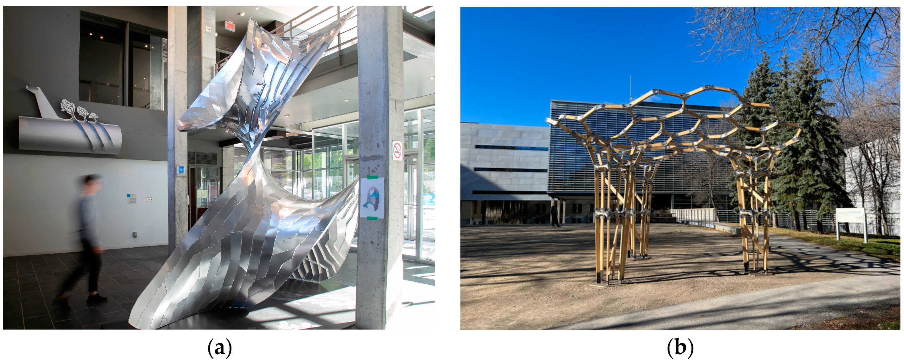
The new methods are presented and tested via large-scale research demonstrators built in an academic setting with un-skilled (i.e., student) labour and simple off-the-shelf tools. The novel methods are detailed in specific sub-sections of the methodology section, while the finalized research demonstrators can be seen in
Figure 1a,b.
4. Methodology
4.1. Deep Structural Skins—The A(Fin)ne Pavilion
The main goal of this research thrust was to develop a new method for constructing large-scale curved architectural surfaces from sheet metal and was achieved through a unified process of discretization and structural optimization. The iterative process involved multiple loops between physical prototypes and computational workflows, culminating in the construction of a large-scale research demonstrator, a curved, free-standing 4.5 m high architectural pavilion. The computational workflows were based on CAD package Rhinoceros 3D, its visual scripting environment Grasshopper, several add-ons, and multiple purpose-built scripted tools. The process as presented facilitates the construction of the final prototype; however, the resulting technique has much broader applications in terms of scale and form. The workflow is composed of several steps presented in their respective subsections below.
4.1.1. Surface Pre-Processing
The first step concerned the creation of the architectural surface and its preparation for discretization. The base surface is constructed as a loft between two arbitrary curves, which is then transformed into a mesh. This mesh is relaxed using the particle-based physics simulation engine Kangaroo [
28] inside Grasshopper, with a soap film (quasi-minimal surface) goal used for the relaxation. To accommodate the manual assembly of parts, the form-found mesh is re-meshed with an average mesh edge length of 16 cm.
4.1.2. Structural Evaluations
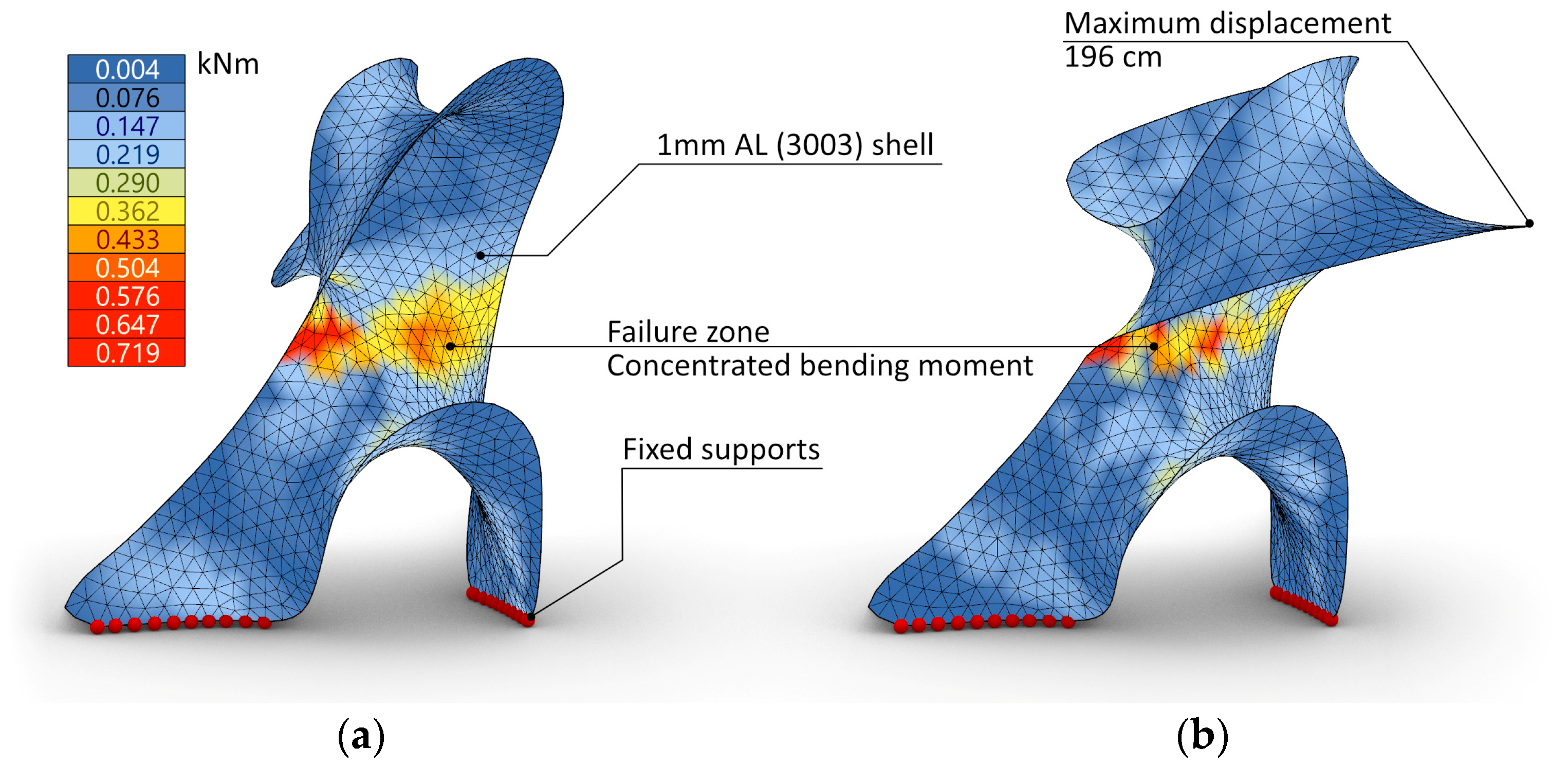
In the second part of the process, the structural properties of the found mesh were tested using the Grasshopper extension Karamba [
29] to gain insight into the surface’s behavior under load. The mesh was evaluated as an aluminum shell with a constant thickness of 1 mm, rigid supports with no degrees of freedom, and subjected to self-weight. The result of the simulation showed that the model exhibits a large deformation mostly caused by the weight of the cantilevering part. The model deforms around an axis defined by a linear area of close to zero Gaussian curvature in the midsection of the surface. The structure’s upper part would collapse due to the limited bending resistance of the 1 mm aluminum sheet material and the lack of curvature perpendicular to the bending forces in the object’s midsection.
Figure 2 shows the testing setup and the results of the simulation.
4.1.3. Discretization for Assembly and Structural Optimization
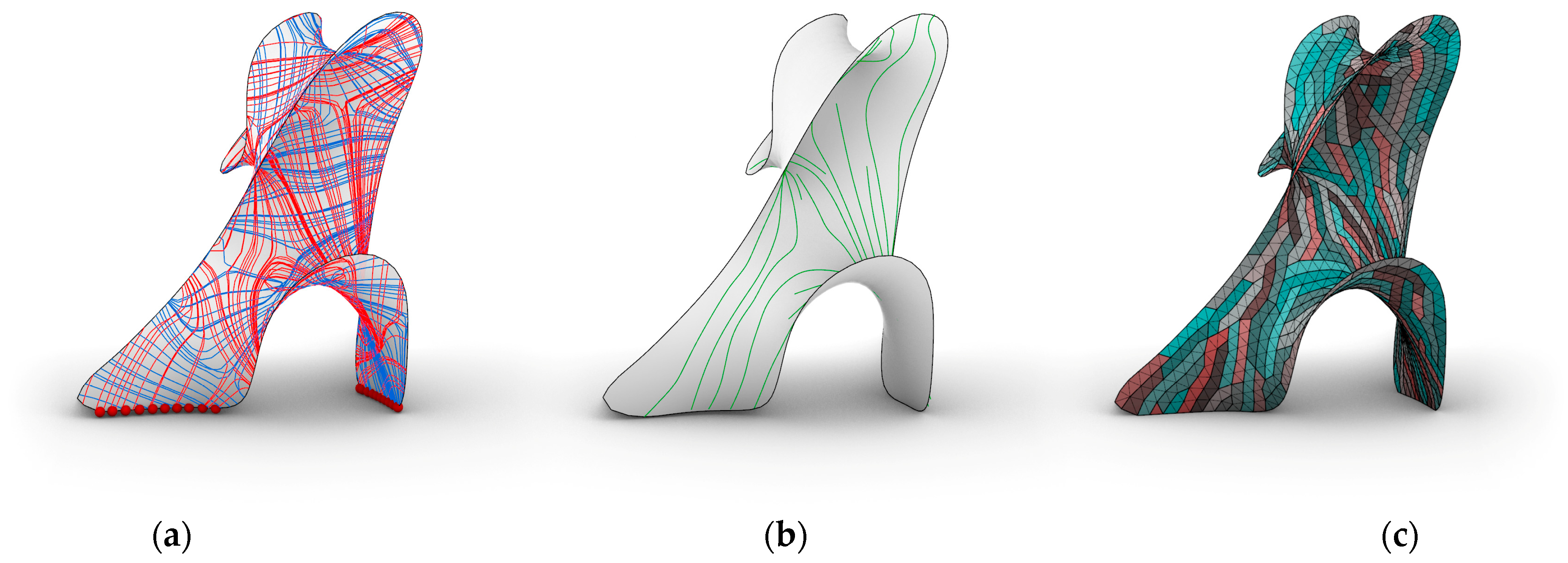
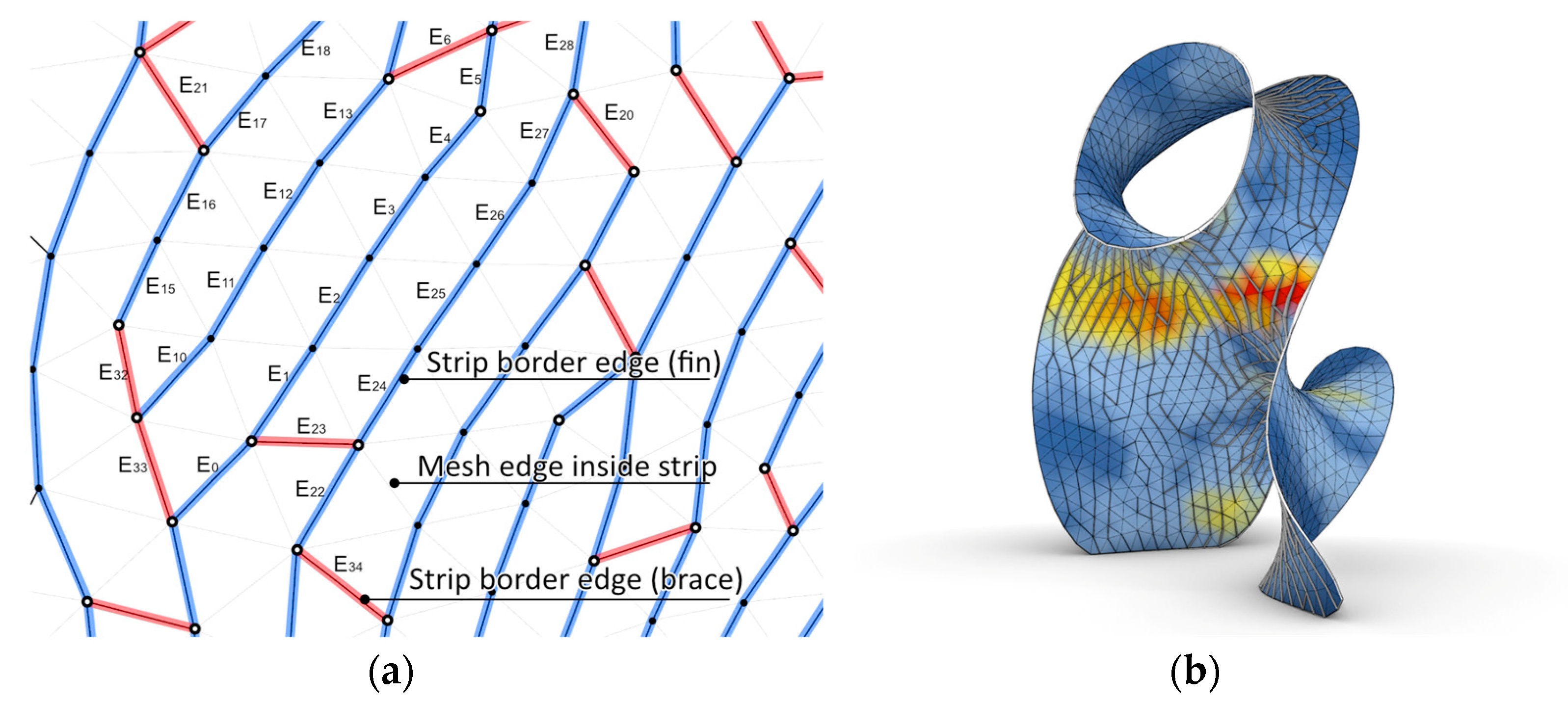
The process of discretization for assembly and structural optimization is a key element in the proposed workflow. It involves the strategic division of the architectural surface into manageable parts, or “discrete parts”, that can be assembled with ease. This process is guided by a structural analysis of the surface from the previous step, which helps to determine the optimal pattern for discretization. The mesh created in step 1 is divided into strips by a series of agents that walk the geometry from mesh face to mesh faces aligning their walks to the principal bending moment field computed in step 2. Each agent has a maximum number of steps to limit the strip length.
The extra material required for the assembly of these discrete parts (i.e., the assembly tabs) is utilized to reinforce the base surface, thereby enhancing the structural integrity of the entire construction. For this, the tabs are connected along the bending moment field with a series of aluminum fins running perpendicular to the surface. Since the bending rigidity of the original base surface varied greatly due to its geometry, the requirement of added rigidity was very different for certain areas and for certain directions. To compensate for that, the width of the fins was modulated according to the value of the bending moment calculated in the previous step and interpolated and stored for each vertex of the mesh. The variable width fins connected to the strips produced a structural skin with variable depth.
Figure 3 presents the discretization process and
Figure 4 presents the relationship between skin depth and bending moment values visualized on the surface.
4.1.4. Fabrication Data
The segmented parts of the mesh (i.e., the strips) and the structural fins are unfolded flat and augmented with the necessary extra geometry to facilitate the construction (i.e., bolt holes and assembly tags). The resulting flat geometry is nested in rectangles representing the available aluminum sheets to be laser-cut for production.
4.1.5. Implementation and Testing
Before the full-scale pavilion was built, several partial prototypes were tested to fine-tune the fabrication variables (i.e., bending tolerances, pre-cut hole placement, assembly tags, etc.). The final full-scale prototype was built over the course of 5 days by the students and two tutors of the master’s studio with hand tools only and with no scaffolding. The research demonstrator stood 4.5 m tall, had 202 laser-cut strips, 465 fins, approximately 3200 bolts, and a surface area of 16.7 SQM. The prototype was on display for 3 months inside the Faculty of Environmental Design at University of Montreal.
4.2. Lightweight Folded Structural Nodes—The NœudAl Pavilion
The research brief that instigated the development of the nodes was for a large span, bespoke geometry structure with a close to funicular shape, with overhangs, constructed from reclaimed short (i.e., <1.5 m) construction lumber, buildable without heavy or complex equipment. This, translated into a node design, meant an adaptable, inexpensive yet stiff node able to transmit axial forces while, at the same time, withstanding bending.
The research is composed of two main concurrent thrusts: network optimization and node construction. The first concerned the creation and optimization of the topology and geometry of the reticular structure. The second concerned the design of a metal node capable of accommodating the available timber members in the proposed configuration. The two thrusts were reciprocally determinant as the research progressed in a continuous loop between network and node optimization.
4.2.1. Network Optimization
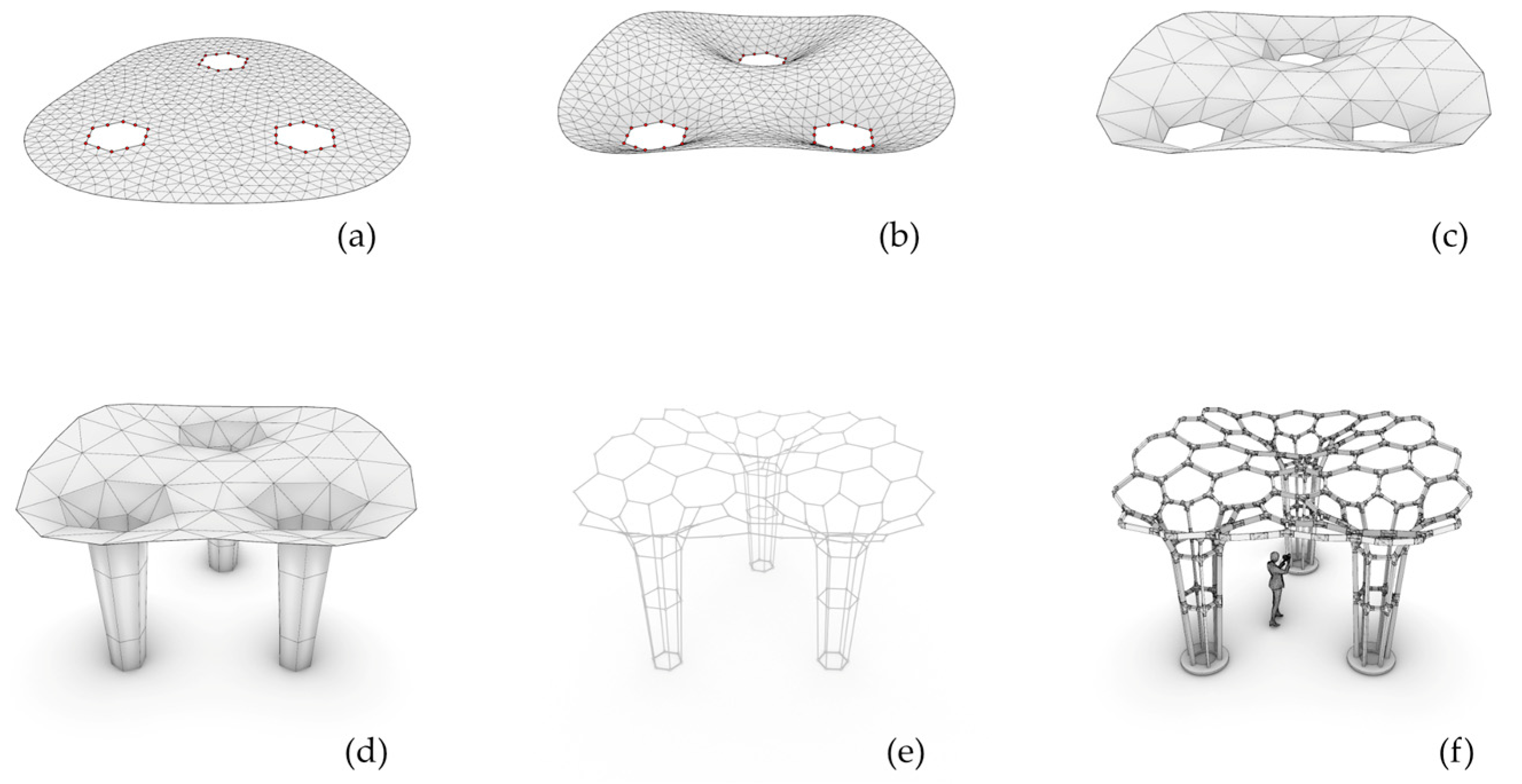
To avoid as much as possible bending and/or torsion in the nodes, the chosen general shape was developed to preponderantly transmit axial efforts. To obtain this, a surface mesh was relaxed under an inverse gravitational force using the Grasshopper physical simulation engine Kangaroo. The mesh was relaxed with a series of vertices forming three independent hexagons anchored to the ground. This resulted in a funicular shape resting on three legs.
Fabrication limitations and budget conditions limited the node complexity and, thus, their valence. As a result, tetrahedralization or even triangulation in the structural network was impossible. To keep the node valence low, we decided the base shape will be approximated by a one-layer structure with polygonal faces. To achieve this, the original fine-grained triangular mesh in
Figure 5a is deformed with Kangaroo,
Figure 5b, and then re-meshed into a coarser triangular mesh with edge lengths close to the average length of the target construction timber kit, shown in
Figure 5c.
Since the re-meshing and the dual making process were producing unusable results for the pavilion legs, we used it solely for the canopy. To facilitate the connection with the legs, the canopy anchor vertices (in red in
Figure 5b) were set up as three regular hexagons, one for each leg. Based on the three hexagons, the legs were constructed using a parametric approach duplicating the starting contours (hexagons) towards the ground and connecting the resulting polygons into tapered tubes, seen in
Figure 5d. The resulting network contained two and three valence nodes for the canopy and four valence nodes for the legs.
To reduce node valence, the dual of the resulting triangular mesh was computed producing a series of non-planar polygons. To reduce the overhangs as well as the short members produced by the dual, the edges touching naked mesh vertices were discarded, seen in
Figure 5e. The resulting network geometry (i.e., the edges of the canopy dual) had lengths already compatible with the available timber kit, comprised of standard 2 × 4 (38 by 89 mm) construction timber. To maximize the use of the kit, using a custom algorithm, each edge length was snapped to the closest available length (i.e., fractions of, or whole lengths of timber in the kit) rounded to the nearest cm.
Figure 5f shows the final geometry.
4.2.2. Node Development
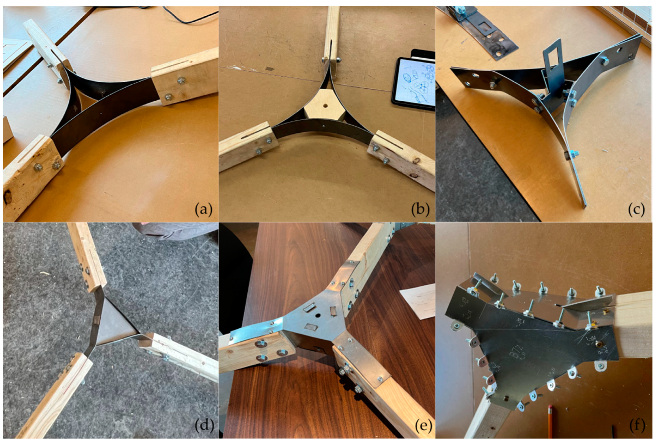
Since cost, fabrication time, and construction tools were all limited, prefabrication avenues for metal fabrication techniques like casting, 3D printing, and machining were considered unfeasible. Reconfigurable nodes, both low-tech and high-tech, were also considered unfeasible due to the limited angle precision and low resulting stiffness. Since most of the techniques of choice for constructing full-scale custom nodes for reticular structures were inaccessible due to our specific context and due to the requirements of our research brief, we focused on a mix of low-cost digital fabrication and simple on-site crafting techniques to build the required structural nodes. More specifically, the work focused on laser-cut and hand-bent sheet metal. The chosen technique was promising based on several of our required criteria. It was relatively cheap to fabricate for bespoke nodes, easy to assemble and install, and offered an adequate degree of precision. The potential downfall of the technique was the lack of stiffness (specially to bending) that turned out to be our main issue during the research process.
Figure 6a–f shows the most important milestones (i.e., prototypes) in the development of the three-valence node.
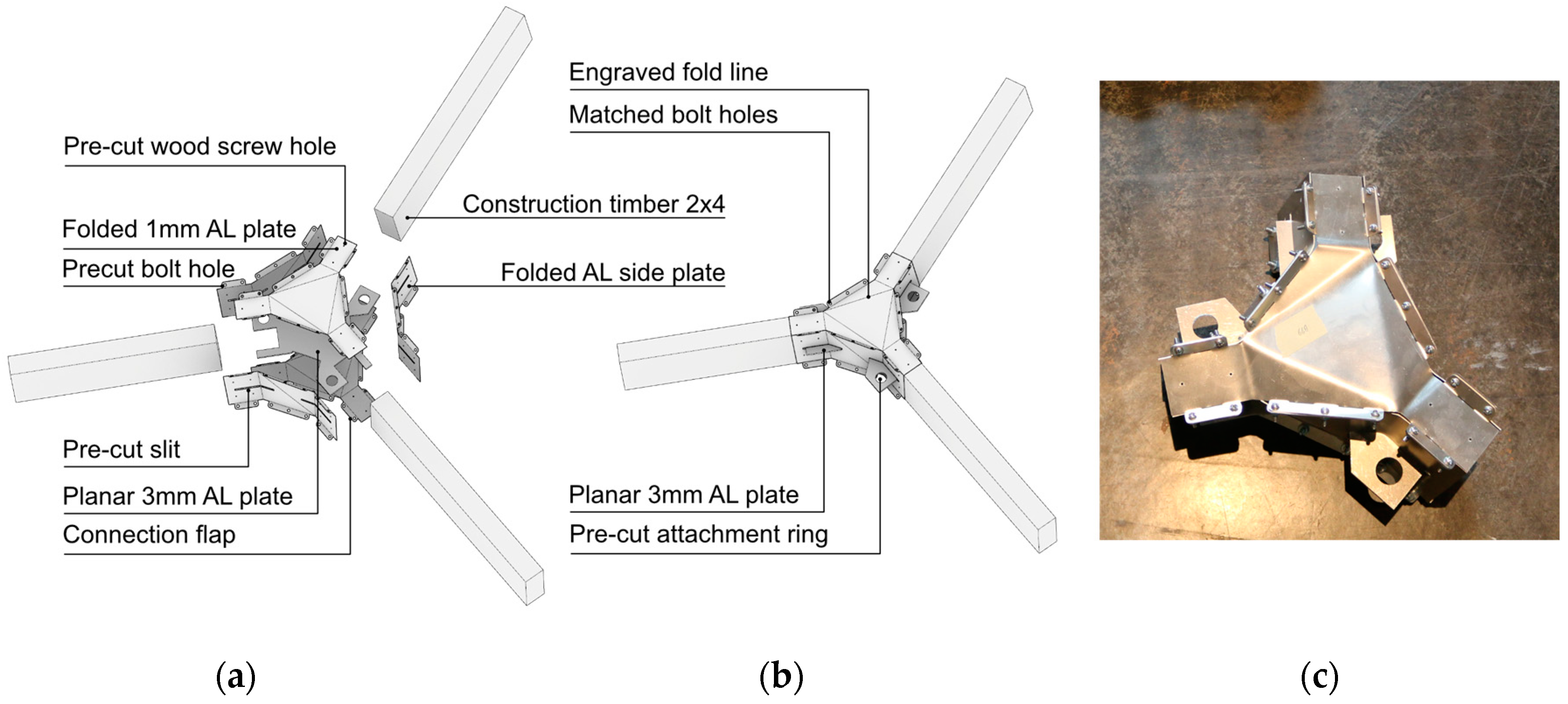
The final design of the three-valence node is shown in
Figure 7. Five laser-cut 1 mm aluminum plates were pre-bent and assembled into a shell for the node. During the assembly, a custom-cut 3 mm planar aluminum plate is introduced inside the node shell. The flat plate contains three two-digit forks that are designed to latch onto the wooden studs as they are inserted into the node. The 3 mm center plate inhibits the rotation of the studs in the plane of the node. The outer shell plates are designed with connection tabs, pre-cut holes for bolts and wood screws, and with a series of slits that allow the center plate forks to embrace the stud ends outside of the node shell. To enable the hand assembly process, the aluminum plates are engraved with fold lines and text tags. The engraved text denotes the plate-to-plate connections and the node-to-edge relationships. The average node weight is 350 g.
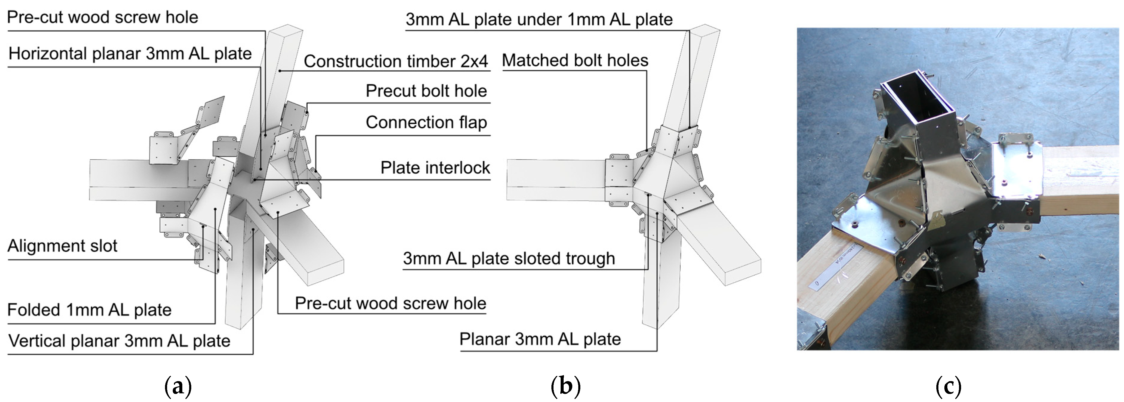
The final three valence node design was used as a template for the two valence and four valence nodes in the structural network. The two valence nodes had a simple design that used only four folded 1 mm aluminum plates to create a tubular shell that connected the two studs. The four valence node posed a more complex challenge as the topology of the node shell had to cater to four studs with divergent directions that could not be assimilated to a set of in-plane connections. As a result, to create the geometry of the shell, a new strategy was implemented that produced all the pairwise relationships between the network edges (studs) meeting in a node and ensuite created the six folded plates that were defined by those connections. To stiffen the node, three 3 mm planar plates were used. The construction of those plates took advantage of the fact that in each four valence node, two of the incoming edges were contained in a common horizontal plane while the other two in a common vertical one. The 3 mm planar plates included in the node shell were interlocked to further stiffen the node. As with the three valence version, the unique laser-cut contour of each plate, together with the pre-cut bolt and screw holes, made for a unique assembly sequence that was further specified by the tags and fold lines engraved on the plates.
Figure 8 shows the design of the four valence node.
5. Discussion and Limitations
The research presented in this paper demonstrates two innovative uses of low thickness aluminum sheets as structural material in construction. The fabrication-oriented approach that relied on a research–design–prototyping loop was very effective in advancing the proposed solutions up to the building of large-scale demonstrators. However, as the process relied heavily on unskilled manual labor and on a time limited development cycle, several issues of the two pavilions were solved with ad hoc solutions. As a result, the two workflows will require further fine tuning before producing solutions with a large applicability in the construction industry.
Bending aids. One of the most prevalent issues was the error resulting from the hand bending of the metal sheet. As the bend location was only engraved and the sheet was not weakened along the folding line, the manual bending often produced inaesthetic results (i.e., variable bending radius, over or under bending, warping, etc.)
Large piece assembly. The individual parts of the construction were designed to be assembled manually and in small teams. However, successive assembly steps produced large pieces with low stiffness due to incomplete shapes. Those parts proved very challenging to assemble due to temporary deformations and required the use of creative assembly solutions (i.e., suspending the parts) to finish the build.
In depth FEA and testing. The use of a structural simulation was integral to define and understand the behavior of the proposed demonstrators. However, due to time and budget limitations, it was impossible to use FEA with a higher level of detail that could include the connection between the pieces, which is one of the most important aspects of the research. As a result, a lot more prototyping work was required for the development, thus reducing the number of possible iterations and explored solutions. Furthermore, the built protypes were only empirically tested and if the solutions are to be deployed on a larger scale, the structural capacity needs to be proven in a laboratory setting before a market-ready solution can be proposed.
6. Conclusions
In this paper, we have shown two new workflows integrating low-thickness aluminum sheets in structural applications, either as a unique material or in combination with construction timber. The research integrates computational design with an affordable digital fabrication and manual assembly to propose viable alternatives to the existing construction paradigm in bespoke architectural structures. Our proposed solutions combine the advantages of high-precision, high-performance numerically controlled fabrication with the versatility and relative low cost of unskilled manual assembly. They also show that a low-cost ubiquitous material mostly used for aesthetic applications in architecture has serious structural utility if combined with smart geometries managed by computational design.
Funding
This research was funded by Fonds de recherche du Québec—Nature et technologies, grant number 310648, Natural Sciences and Engineering Research Council of Canada, grant number RGPIN-2022-04256, ALUQUEBEC, and University of Montreal School of Architecture.
Institutional Review Board Statement
Not applicable.
Informed Consent Statement
Not applicable.
Data Availability Statement
Data is contained within the article.
Acknowledgments
The author of the paper acknowledges, as co-authors of the final built prototypes, the team of students and tutors of the ARC 6801H research studio. 2021 A(fin)ne Pavilion: Students: Alphonso Francis, Belanger Nicolas, Berube Camille, Faltas Youstina, Gamachio Eva, Langelier Marc-Antoine, Larouche-Wilson Kevin, Mansy Mariam, Mireault Pierre-Alexandre, Morissette Olivier, Nahra Ellie, Poulin Delphie, St-Hillaire Caroline; Tutors: Thomas Balaban and Andrei Nejur. 2022 NœudAL pavilion: Students: Marc-Antoine Boulé, Christian Camilo Molina Gonzalez, Charles Cauchon, Anaïs Duclos, Grégoire Gaudreault, Kévin Larouche-Wilson, Juliette Mezey, Sarah Murray, Lucas Ouellet, Mohamed Seddiki.
Conflicts of Interest
The author declares no conflict of interest.
References
- Dwight, J. Aluminium Design and Construction; CRC Press: Boca Raton, FL, USA, 1998. [Google Scholar]
- Lane, J. Aluminium in building; Routledge: London, UK, 2018. [Google Scholar]
- Eversmann, P.; Ehret, P.; Ihde, A. Curved-folding of thin aluminium plates: Towards structural multi-panel shells. In Proceedings of the IASS Annual Symposia, International Association for Shell and Spatial Structures (IASS), Hamburg, Germany, 25–28 September 2017; pp. 1–10. [Google Scholar]
- Georgantzia, E.; Gkantou, M.; Kamaris, G.S. Aluminium alloys as structural material: A review of research. Eng. Struct. 2021, 227, 111372. [Google Scholar] [CrossRef]
- Dyvik, S.; Manum, B.; Mork, J.; Luczkowski, M. Structural aluminum in architecture—The history and future of aluminum as a structural material. In Proceedings of the 4th International Conference on Structures and Architecture (ICSA 2019), Lisbon, Portugal, 24-26 July 2019. [Google Scholar]
- Eigensatz, M.; Deuss, M.; Schiftner, A.; Kilian, M.; Mitra, N.J.; Pottmann, H.; Pauly, M. Case studies in cost-optimized paneling of architectural freeform surfaces. Adv. Archit. Geom. 2010, 2010, 49–72. [Google Scholar]
- Pottmann, H. Architectural geometry and fabrication-aware design. Nexus Netw. J. 2013, 15, 195–208. [Google Scholar] [CrossRef]
- Flöry, S.; Pottmann, H. Ruled surfaces for rationalization and design in architecture. In Proceedings of the ACADIA 2010 Conference, New York, NY, USA, 21–24 October 2010. [Google Scholar]
- Fornes, M. The art of the prototypical. Archit. Des. 2016, 86, 60–67. [Google Scholar] [CrossRef]
- Schleicher, S.; Rastetter, A.; La Magna, R.; Schönbrunner, A.; Haberbosch, N.; Knippers, J. Form-finding and design potentials of bending-active plate structures. In Modelling Behaviour; Springer: Berlin/Heidelberg, Germany, 2015; pp. 53–63. [Google Scholar]
- Magna, R.L.; Gabler, M.; Reichert, S.; Schwinn, T.; Waimer, F.; Menges, A.; Knippers, J. From nature to fabrication: Biomimetic design principles for the production of complex spatial structures. Int. J. Space Struct. 2013, 28, 27–39. [Google Scholar] [CrossRef]
- Demin, D. The Rose Pavilion. In Proceedings of the IASS Annual Symposia; International Association for Shell and Spatial Structures (IASS): Madrid, Spain, 2015; pp. 1–9. [Google Scholar]
- Rossi, G.; Nicholas, P. Modelling a complex fabrication system: New design tools for doubly curved metal surfaces fabricated using the English Wheel. In Proceedings of the 36th eCAADe 2018: Computing for a Better Tomorrow, Lodz, Poland, 19–21 September 2018; pp. 811–820. [Google Scholar]
- Cai, Z.-Y.; Lan, Y.-W.; Li, M.-Z.; Hu, Z.-Q.; Wang, M. Continuous sheet metal forming for doubly curved surface parts. Int. J. Precis. Eng. Manuf. 2012, 13, 1997–2003. [Google Scholar] [CrossRef]
- Friedman, T. Foldfinding-a Novel Approach to the Design and Fabrication of Folded Structures. In Proceedings of IASS Annual Symposia; International Association for Shell and Spatial Structures (IASS): Madrid, Spain, 2016; pp. 1–10. [Google Scholar]
- Lienhard, J.; Knippers, J. Considerations on the scaling of bending-active structures. Int. J. Space Struct. 2013, 28, 137–148. [Google Scholar] [CrossRef]
- Martín-Pastor, A.; García-Alvarado, R. Developable wooden surfaces for lightweight architecture: Bio-dune pavilion. Digit. Wood Design 2019, 24, 1481–1500. [Google Scholar]
- Nicholas, P.; Stasiuk, D.; Nørgaard, E.; Hutchinson, C.; Thomsen, M.R. An integrated modelling and toolpathing approach for a frameless stressed skin structure, Fabricated using robotic incremental sheet forming. Robot. Fabr. Archit. Art Des. 2016, 2016, 62–77. [Google Scholar]
- Schmieder, M.; Mehrtens, P. Cladding Freeform Surfaces with Curved Metal Panels—A Complete Digital Production Chain. In Advances in Architectural Geometry 2012, Hesselgren, L.; Sharma, S., Wallner, J., Baldassini, N., Bompas, P., Raynaud, J., Eds.; Springer: Vienna, Austria, 2013; pp. 237–242. [Google Scholar]
- Rochas, A. Universal Node for Space Frame Structures. US8820025B1, 2 September 2014. [Google Scholar]
- Dyvik, S.H.; Manum, B.; Luczkowski, M. Structural aluminium nodes in free form reticulated structures-geometric variables and manufacturing constraints. In Proceedings of the IASS Annual Symposia; International Association for Shell and Spatial Structures (IASS): Madrid, Spain, 2019; pp. 1–8. [Google Scholar]
- Carpo, M. The Alphabet and the Algorithm; Mit Press: Cambridge, MA, USA, 2011. [Google Scholar]
- Chilton, J.; Taylor, S.G.S. Space Grid Structures; Taylor & Francis: London, UK, 2007. [Google Scholar]
- Abdelwahab, M.M.; Tsavdaridis, K.D. Optimised 3D Printed Metallic Node-Connections for Reticulated Structures. In Proceedings of the 9th International Conference on Steel and Aluminium Structures (ICSAS19), Bradford, UK, 3–5 July 2019; pp. 423–434. [Google Scholar]
- Seifi, H.; Javan, A.R.; Xu, S.; Zhao, Y.; Xie, Y.M. Design optimization and additive manufacturing of nodes in gridshell structures. Eng. Struct. 2018, 160, 161–170. [Google Scholar] [CrossRef]
- Hassani, V.; Khabazi, Z.; Mehrabi, H.A.; Gregg, C.; O’Brien, R.W. Rationalization algorithm for a topologically-optimized multi-branch node for manufacturing by metal printing. J. Build. Eng. 2020, 29, 101146. [Google Scholar] [CrossRef]
- St-Hilaire, C.; Nejur, A. WoodN—In search of a constructive system for a sustainable temporary architecture. In Proceedings of the 40th Conference on Education and Research in Computer Aided Architectural Design in Europe (eCAADe 2022), Ghent, Belgium, 13–16 September 2022; pp. 185–094. [Google Scholar]
- Piker, D. Kangaroo Physics. 2013. Available online: https://www.food4rhino.com/en/app/kangaroo-physics (accessed on 11 May 2023).
- Preisinger, C.; Heimrath, M. Karamba—A toolkit for parametric structural design. Struct. Eng. Int. 2014, 24, 217–221. [Google Scholar] [CrossRef]
- Nejur, A.; Steinfeld, K. Ivy: Progress in Developing Practical Applications for a Weighted-Mesh Representation for Use in Generative Architectural Design. In Proceedings of the 37th Annual Conference of the Association for Computer Aided Design in Architecture (ACADIA 2017), Cambridge, MA, USA, 2–4 November 2017; pp. 446–455. [Google Scholar]
| Disclaimer/Publisher’s Note: The statements, opinions and data contained in all publications are solely those of the individual author(s) and contributor(s) and not of MDPI and/or the editor(s). MDPI and/or the editor(s) disclaim responsibility for any injury to people or property resulting from any ideas, methods, instructions or products referred to in the content. |
© 2023 by the author. Licensee MDPI, Basel, Switzerland. This article is an open access article distributed under the terms and conditions of the Creative Commons Attribution (CC BY) license (https://creativecommons.org/licenses/by/4.0/).


