Abstract
Aluminum appears as a promising structural material as it shows many benefits such as a great strength to weight ratio, low maintenance costs, resistance to corrosion, recyclability, etc. Accordingly, characterizing the behavior and resistance of different aluminum sections under various loading conditions is essential. The current paper presents an experimental investigation on aluminum sections with simple and complex geometries to study the effect of cross-section shape on the buckling response of the aluminum sections. Firstly, eight tensile coupon tests were conducted on coupons of aluminum alloy 6061-T6 to accurately determine its material properties. Geometrical imperfections on the surface of each specimen were then measured using a 3D scanner. Further, eight stub column tests were also performed to study the behavior of I, H and complex cross-sections under pure compression. In addition to this, 12 cross-section tests under combined compression and bending are currently under way to study the buckling behavior of these specimens under eccentric compression.
1. Introduction
Aluminum (Al) is a versatile material with various advantages as a construction material such as a high strength to weight ratio, an excellent resistance to corrosion, low maintenance costs, ease of fabrication, aesthetical appearance, etc. [1]. The 6000 series aluminum alloys are often used in structural applications, and yet, despite the advantages listed, are seldom used in the construction industry. One of the main reasons lies in the response of Al profiles to buckling phenomena (geometric instability under compression), owing to a rather lower elastic modulus (one-third that of carbon steel), and due to a limited knowledge base regarding its mechanical behavior. The stability issues of Al shapes can be improved by increasing the stiffness of the cross-sections considered. Higher stiffness can be achieved by using hollow cross-sections, complex cross-sections or even (stiffened) open cross-sections that yield higher moments of inertia. In this regard, current design standards, such as the Canadian Standard CSA S157 [2], Eurocode EC9 [3] and the American Standard—Aluminum Design Manual (ADM) [4], provide buckling design provisions that are applicable to cross-sections with a regular geometry such as I, H, rectangular hollow, square hollow sections, etc. However, for cross-sections with a complex geometry, there are no direct design rules. Even in the case of regular cross-sections, resistance predictions as per these standards are not accurate.
Various studies on different aluminum cross-section shapes such as angle, I, stiffened closed section, H and rectangular hollow section show that current design standards predict conservative resistance values [5,6]. However, some research works have shown that current standards sometimes overestimate the resistance value. For example, Wang et al. (2018) [7] from their investigation on large sections of extruded Al alloy I and rectangular hollow sections (RHSs) found that although Eurocode EC9 and Chinese Code GB 50,429 give conservative resistance values, the American Aluminum Design Manual overestimated resistance values, which indicated unsafe predictions. Similarly, Zhang et al. (2020) [8] found that current design provisions yield unsafe and scattered predictions for pin-ended unequal angle columns. Therefore, extensive research is necessary to analyze buckling in different cross-sections, including complex cross-sections with varying loading conditions, geometries, and boundary conditions to reach a common conclusion and thus accurately predict resistance values.
Therefore, this article presents a part of a study in which a thorough experimental and numerical investigation will be conducted on different extruded Al cross-section shapes under axial and eccentric compression, followed by a design proposal based on “The Overall Interaction Concept” (O.I.C.) [9]. However, the current objective of this article is to experimentally investigate the local buckling behavior of Al open cross-sections (I and H cross-sections), as well as of two types of complex cross-sections that are often used in bridge applications. In this respect, 8 stub column tests have been performed and 14 tests under eccentric compression are under way. In addition, and prior to these tests, eight tensile coupon tests and measurements of geometrical imperfections have also been performed to provide accurate material properties and surface geometries, respectively.
2. Details of Experimental Testing
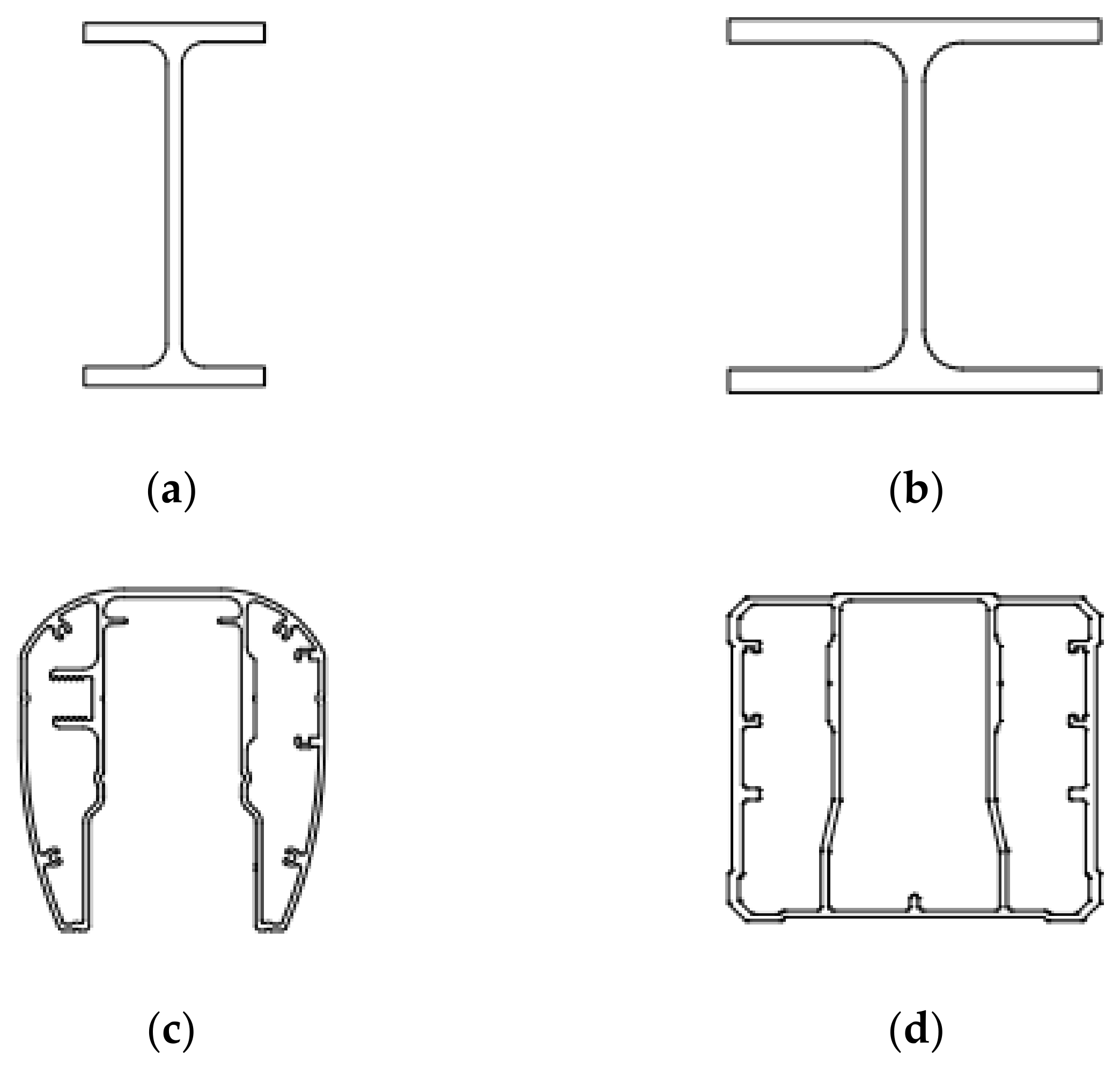
Four types of Al cross-sectional shapes were considered in this study, i.e., I cross-section I6 × 92, H cross-section WF6 × 7.61, and two types of complex cross-sections, ME001 and ME044, as shown in Figure 1. On these specimens, preliminary analyses such as dimension measurements, tensile coupon tests and geometrical imperfection measurements were performed to obtain the accurate material and geometric properties. Complete details of the dimension measurements of these specimens can be found in [10]. The details of all the experimental investigations are provided in the following subsections.
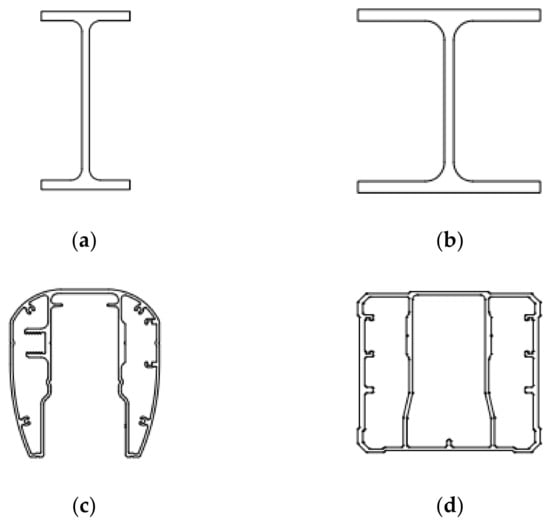
Figure 1.
Cross-sections considered in this study: (a) I cross-section; (b) H cross-section; (c) complex cross-section ME001; (d) complex cross-section ME044.
2.1. Measurement of Geometric Imperfections
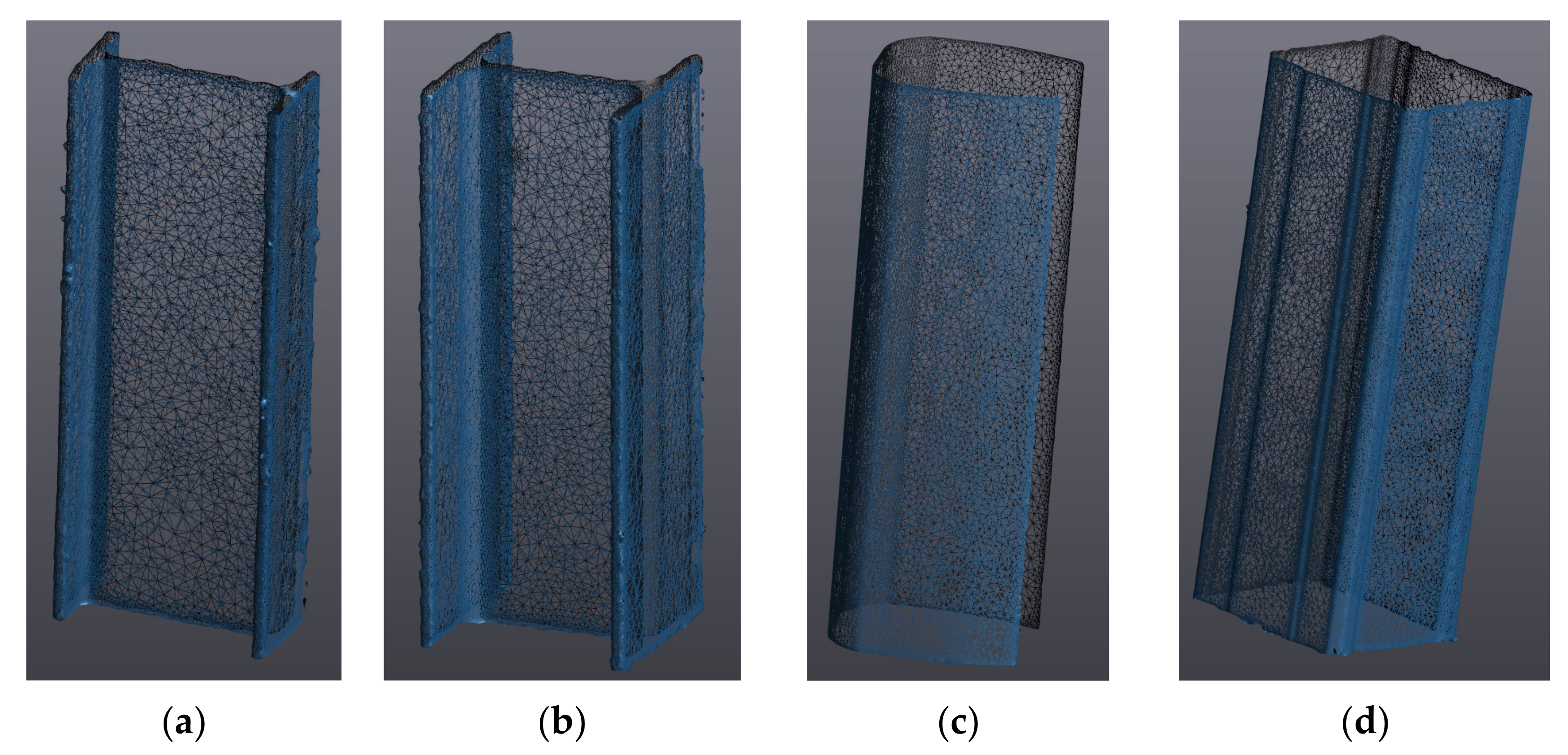
Geometric imperfections significantly affect the buckling capacity as well as buckling deformation shapes of aluminum specimens and thus their accurate measurement is crucial. Geometric imperfections for all the cross-section specimens, i.e., I, H and complex cross-sections ME001 and ME044 were measured by 3D scanning technology which involves scanning the specimen surface using a handy MetraScan which is used in coordination with a C-Track device, with the help of VXelements software. This device is capable of measuring imperfection amplitudes up to an accuracy of 0.025 mm. Figure 2 shows the scanned geometrical imperfections of all the specimens considered in this study. The database on the geometrical imperfections will be utilized in the future scope of this study to validate the numerical models of these sections in ABAQUS as well as to investigate the influence of geometrical imperfections on their buckling behavior under axial and eccentric compressions.
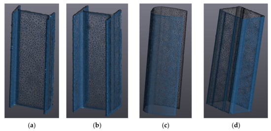
Figure 2.
Scanned geometrical imperfections of cross-sections: (a) I cross-section; (b) H cross-section; (c) complex cross-section ME001; (d) complex cross-section ME044.
2.2. Tensile Coupon Tests
Tensile coupon tests are performed to characterize the actual material behavior of the specimens, especially the stress–strain relationship. A total of eight tensile coupon tests were performed, two from each cross-section specimen, to ensure the accuracy of tests. The coupons were manufactured according to the ASTM standards [11] and cut out from flanges and webs of the specimens. The coupons were tested using a 500 kN MTS hydraulic testing machine under displacement-controlled conditions. The loading procedure and rate followed the procedures outlined in [12]. Figure 3a shows the tested coupons for I and H cross-section specimens and Figure 3b shows the tested coupons for the complex cross-sections ME001 and ME004. Table 1 presents the obtained Young’s modulus , yield strength taken as 0.2% proof stress , 1.0% proof stress and the ultimate tensile strength of the tested coupons.
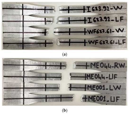
Figure 3.
Tested tensile coupons for (a) I and H sections; and (b) complex cross-sections of two types, i.e., ME044 and ME001.

Table 1.
Material properties obtained from tensile coupon tests.
As per the Canadian Standard CSA S157 [2], the yield strength, ultimate strength and modulus of elasticity for 6061-T6 Al alloy are 240 MPa, 260 MPa and 70,000 MPa, respectively. However, the measured properties from tensile coupon tests varied from CSA S157 by up to 25% for yield and ultimate strength, and up to 5% for modulus of elasticity as can be seen in Table 1. This observation shows the significance of carrying out tensile coupon tests to obtain accurate material properties. These experimentally obtained values will be employed in the ABAQUS software to validate the models for these sections which will further be utilized in performing a comprehensive numerical study on investigating the local buckling behavior of such specimens in the future course of this study.
2.3. Stub Column Tests
Stub column tests are performed to characterize the buckling behavior of a specimen under axial compression. In this study, eight stub column tests were performed, with each test being repeated for every cross-section shape to ensure the accuracy of the test results. The length of each specimen was chosen as three times the maximum height of the cross-section to avoid the chance of flexural or member buckling. Fixed-fixed boundary conditions were provided at both the top and bottom of the specimen, except axial displacement at the top plate so as to allow the specimen to compress in the longitudinal direction. The tests were performed using a 5000 kN SATEC testing machine under displacement-controlled conditions and axial displacement; end shortening was measured through a displacement transducer placed at the top of specimen as shown in Figure 4.
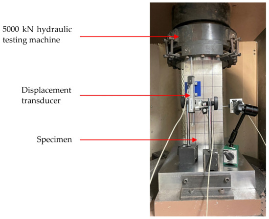
Figure 4.
Experimental setup for stub column tests.
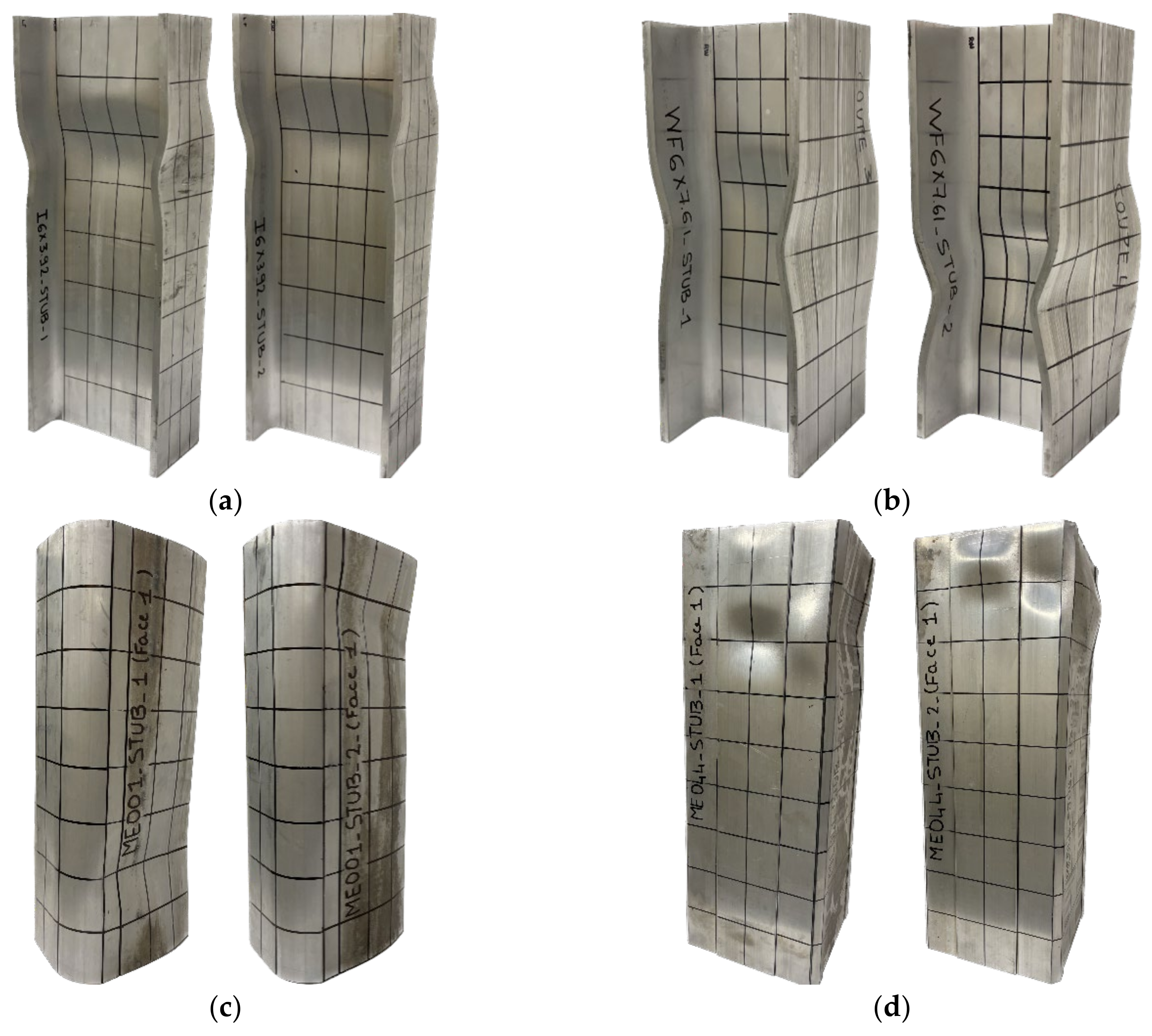
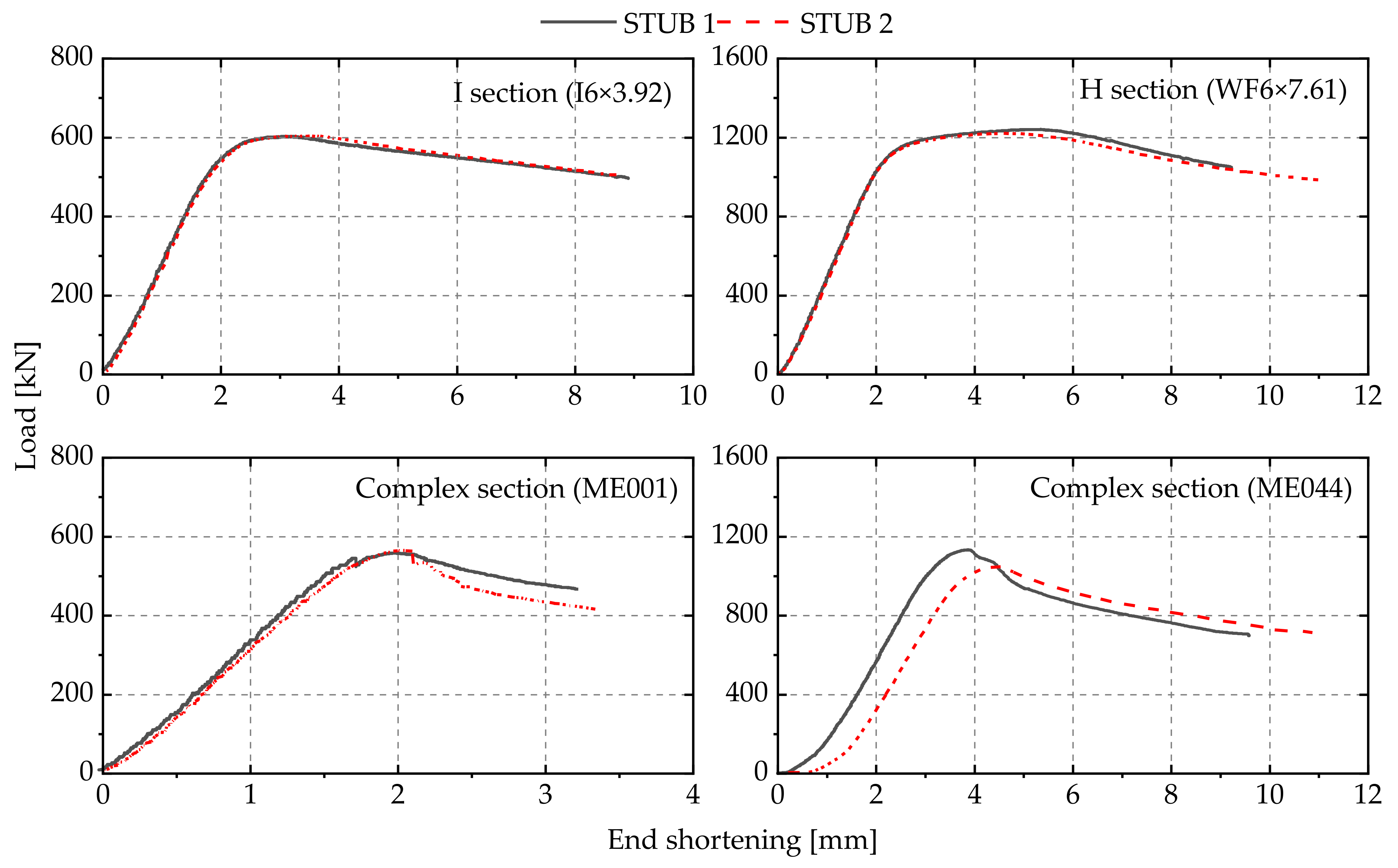
Figure 5 shows the buckling failure modes for all the cross-section specimens and it can be seen that all specimens have undergone local buckling failure. Also, failure modes for the repeated tests were similar to the first ones for all the cross-section specimens, indicating the reliability of tests. The repeatability of the tests is also evident from Figure 6 where the STUB 1 graph representing the first test almost overlaps with the corresponding repeated tests represented as STUB 2 in the case of all the sections except ME044. A slight shift between the two tests can be observed for the complex cross-section ME044, which can be attributed to the fact that the gap between end plate and the specimen was not completely closed before the start of the test.

Figure 5.
Tested stub column specimens: (a) I-section; (b) H-section; (c) complex section ME001; (d) complex section ME044.
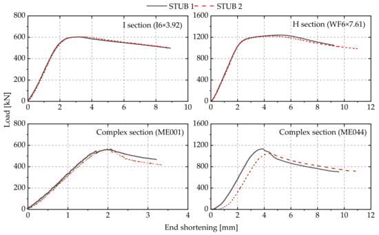
Figure 6.
Load-end shortening curves for stub column tests.
Table 2 presents the peak load attained () and the corresponding displacement for all the specimens from experimental testing, along with a comparison of resistance predictions from the Canadian Standard CSA S157. It can be observed that resistance predictions from CSA S157 (NCSA-157) are higher than test results by around 25 to 30% for I and H cross-sections showing the conservative nature of design standards. The resistance predictions for complex cross-sections ME001 and ME044 from CSA S157 is a part of a future study. However, it can be intuitively said that resistance predictions for complex cross-sections would be even more conservative owing to their higher stiffness. In the next phase of this study, this database will be employed to validate the existing design standards for predicting the local buckling behavior of aluminum extruded sections as well as verify the numerical models for such sections.
Table 2.
Peak load and corresponding displacement along with comparison with Canadian Standard CSA S157 for stub column tests.
3. Ongoing Work—Eccentric Compression Tests
In order to investigate the buckling behavior of aluminum sections under combined axial compression and bending stresses including both uniaxial and biaxial bending conditions, 12 eccentric compression tests are currently in progress. These tests are being conducted using a 2000 kN MTS hydraulic testing machine under displacement-controlled loading. Pin-ended boundary conditions are employed at both ends of the specimens and are achieved through a cylindrical hinging device in the test setup. This kind of setup allows accurate replication of the structural response under combined compression and bending. The measured load and end shortening data from both the stub column and eccentric compression tests will altogether provide a complete overview on the local buckling behavior of thin-walled extruded aluminum sections of I, H and complex shapes. These observations will eventually contribute towards developing new design rules for improved and efficient designs of aluminum sections under compression and combined loads.
4. Conclusions and Future Work
This work aimed to investigate the local buckling behavior of aluminum cross-sections through undertaking a comprehensive experimental program. In this regard, 8 stub column tests under pure compression were performed while 18 eccentric compression tests are currently underway. The cross-sectional shapes considered in the study are I, H and two types of complex cross-sections. In addition, tensile coupon tests and geometric imperfections measurements were also performed to accurately assess, respectively, the material and geometric properties of these cross-section specimens. It was observed from the stub column tests that all the specimens failed in local buckling while a good agreement between two tests of similar types has indicated the reliability of the test results. Also, resistance predictions from the Canadian Standard CSA S157 were found to be too conservative upon comparison with the experimental results from the stub column tests.
Upon completing the experimental tests, numerical models corresponding to each of these specimens will be developed in ABAQUS software [13] which will further be validated through the experimental observations including ultimate loads, load displacement curves and failure modes. Then, a series of numerical parametric studies will be conducted with the ultimate goal of proposing design equations for Al members, based on the principles of the Overall Interaction Concept (O.I.C.) [14].
Author Contributions
Conceptualization, P.V. and N.B.; methodology, P.V. and N.B.; laboratory experiments, P.V., S.D. and L.L.; formal analysis, P.V.; investigation, P.V., S.D. and L.L.; resources, P.V., S.D. and L.L.; data curation, P.V.; writing—original draft preparation, P.V.; writing—review and editing, P.V., P.D. and N.B.; visualization, P.V.; supervision, P.D. and N.B.; project administration, P.D. and N.B.; funding acquisition, P.D. and N.B. All authors have read and agreed to the published version of the manuscript.
Funding
This research was funded by “Fonds de Recherche du Québec—NATURE ET TECHNOLOGIE (FRQNT)—FT131760”.
Institutional Review Board Statement
Not applicable.
Informed Consent Statement
Not applicable.
Acknowledgments
We would like to thank our industry funding partner MAADI Group Inc. for providing the test specimens. We are thankful to Denis Ouellet for granting us the opportunity to utilize the 3D scanner for this project. Finally, a big thanks to our dedicated technician, Hugues Ferland, without whom we would not have been able to successfully complete this project.
Conflicts of Interest
The authors declare no conflict of interest.
References
- Beaulieu, D.; Marsh, C. Design of Aluminum Structures; Presses de l’aluminium: Québec, QC, Canada, 2006. [Google Scholar]
- Canadian Standards Association. CSA S157-17: Strength Design in Aluminum; Canadian Standards Association: Toronto, ON, Canada, 2017. [Google Scholar]
- European Committee for Standardization. Eurocode 9: Design of Aluminium Structures—Part 1-1: General Structural Rules; Commission of the European Community: Brussels, Belgium, 2007. [Google Scholar]
- Aluminum Association. Aluminum Design Manual: 2020; Aluminum Association: Washington, DC, USA, 2020. [Google Scholar]
- Liu, M.; Zhang, L.; Wang, P.; Chang, Y. Experimental investigation on local buckling behaviors of stiffened closed-section thin-walled aluminum alloy columns under compression. Thin-Walled Struct. 2015, 94, 188–198. [Google Scholar] [CrossRef]
- Yuan, L.; Zhang, Q.; Ouyang, Y. Experimental investigation and design method of the flexural buckling resistance of high-strength aluminum alloy H-columns. In Structures; Elsevier: Amsterdam, The Netherlands, 2022; pp. 1339–1349. [Google Scholar]
- Wang, Y.Q.; Wang, Z.X.; Hu, X.G.; Han, J.K.; Xing, H.J. Experimental study and parametric analysis on the stability behavior of 7A04 high-strength aluminum alloy angle columns under axial compression. Thin-Walled Struct. 2016, 108, 305–320. [Google Scholar] [CrossRef]
- Zhang, Y.; Wang, Y.; Wang, Z.; Bu, Y.; Fan, S.; Zheng, B. Experimental investigation and numerical analysis of pin-ended extruded aluminium alloy unequal angle columns. Eng. Struct. 2020, 215, 110694. [Google Scholar] [CrossRef]
- Coderre, T.; Li, L.; Dahboul, S.; Boissonnade, N. Local buckling and design of aluminum I-shapes. In Proceedings of the Annual Stability Conference Structural Stability Research Council Charlotte, Charlotte, NC, USA, 12–14 April 2023. [Google Scholar]
- Dahboul, S.; Li, L.; Verma, P.; Dey, P.; Boissonnade, N. Experimental investigation on the local stability thin-walled aluminium extrusions of different shapes. In Lecture Notes in Civil Engineering, Proceedings of the Canadian Society for Civil Engineering Annual Conference 2023, Moncton, NB, Canada, 24–27 May 2023; Springer Nature Switzerland AG: Cham, Switzerland, 2023. [Google Scholar]
- ASTM—American Society for Testing and Materials. ASTM B108-15 Standard Specification for Aluminum-Alloy Permanent Mold Castings; ASTM International: West Conshohocken, PA, USA, 2015. [Google Scholar]
- Huang, Y.; Young, B. The art of coupon tests. J. Constr. Steel Res. 2014, 96, 159–175. [Google Scholar] [CrossRef]
- Abaqus, G. Abaqus 6.11; Dassault Systemes Simulia Corporation: Providence, RI, USA, 2011. [Google Scholar]
- Boissonnade, N.; Hayeck, M.; Saloumi, E.; Nseir, J. An Overall Interaction Concept for an alternative approach to steel members design. J. Constr. Steel Res. 2017, 135, 199–212. [Google Scholar] [CrossRef]


Disclaimer/Publisher’s Note: The statements, opinions and data contained in all publications are solely those of the individual author(s) and contributor(s) and not of MDPI and/or the editor(s). MDPI and/or the editor(s) disclaim responsibility for any injury to people or property resulting from any ideas, methods, instructions or products referred to in the content. |
© 2023 by the authors. Licensee MDPI, Basel, Switzerland. This article is an open access article distributed under the terms and conditions of the Creative Commons Attribution (CC BY) license (https://creativecommons.org/licenses/by/4.0/).