Abstract
Lighting is the largest source of electricity consumption. The implementation of new technologies makes it possible to reduce the energy bill as well as the operating costs. In this work, we created a control and management system for exterior lighting using creative, intelligent, and autonomous methods. The project allows control room operators to monitor the system and interact when needed. Our project is subdivided into three major parts, ordering, data processing, and action. The first part is carried out in two modes: manually using an Optocoupler and controlled with a graphical interface by RS232 serial-type communication. The second part is processed by a microcontroller; as for the third part, it controls three poles through an MOC3023 Optotriac IC and BTA16-600B Triac for full and half lighting. For the controlled mode, we used the dimmer principle which works by essentially chopping parts out of the AC voltage. The brightness of the lamp is determined by the power transferred to it, so the more the waveform is chopped, the more it dims. A zero crossing control is needed for phase cutting. The graphical application of our project has a rather rough design. It is divided into two windows: the first consists of a connection window, and the second one is for the main control interface. On this control interface, there are basically three tabs: connection and serial connection status, control, and operating mode.
1. Introduction
Urban nightlife remained limited in the 18th century, and activity in cities stopped when the sun set. At night, the streets become useless, with no movement, and a place filled with crime, and the streets and monuments become an unknown identity. Therefore, the need arose to research what makes life in the city at night similar to what it is during the day in order to protect ourselves from the dangers of the night and ward off the ancestral fear of darkness.
Humans responded by inventing public lighting, offering a reassuring environment and prolonged activity beyond nightfall. Public lighting has been set up for safety reasons; in general, light allows individuals to move in space or defend them-selves and this requires a high level of lighting performance that meets standards and requires the rational use of energy [1]. Thus, how do we adapt public lighting to needs while limiting the impact on the environment and electricity consumption?
In this simple project, we have established a starting step towards efficient use and energy conservation by controlling and managing a lighting system from the comfort of one’s desktop using two necessary components: an electronic system and a graphic user interface. We aim to make lighting systems easily controllable. This work is based on a practical implementation of an Arduino card as a microcontroller and an HMI created by the Python tkinter interface on PC which supports the management of this system by a simple serial communications. This paper is divided as follows: in Section 2, the public lighting and smart control system are discussed. In Section 3, a description of our system and schematic of the electronic circuit are presented, and in Section 4, the results and discussion are mentioned. Finally, in Section 5, the conclusion from our present work is drawn.
2. Lighting and Smart Control Systems
The public lighting system generally consists of roadway lighting offering an improvement in visibility. It is a set of lighting methods used in public places inside and outside the city, usually on the edges of roads, to give a feeling of safety and contributes to the prevention of accidents. The lighting of outdoor spaces must adapt to the evolution of the political framework. It must respond to new environmental and energy challenges, while controlling the economic standards related to the total cost for a successful outdoor lighting installation [2].
One of the easiest ways to save energy is to turn off light fixtures located in unoccupied areas. The control of public lighting can be accomplished in different ways, either by means of simple local switches, motion detectors, photoelectric cells, programmable clocks, or even using computerized lighting control systems [3].
There are four possible strategies for lighting control:
- Program the switching on and/or dimming times. For a system with reduced illumination, it is necessary to install dimmable lamps or two non-dimmable lamps per street lamp.
- Lighting of individual streetlights is managed by motion detectors or presence detectors and with a programmable switch-off delay.
- Combination of programmed ignition, natural light function. and/or motion detection. This option can be useful, for example, if you want to reduce the lighting intensity at night or only on request.
- Advanced systems that use software and hardware to automate the control of lighting in a building. Some of the benefits of computerized lighting control systems include the ability to monitor and control lighting usage in real time.
3. System Description and Schematic of the Electronic Circuit
As pointed out above, our project was subdivided into three major parts, ordering, data processing, and action.
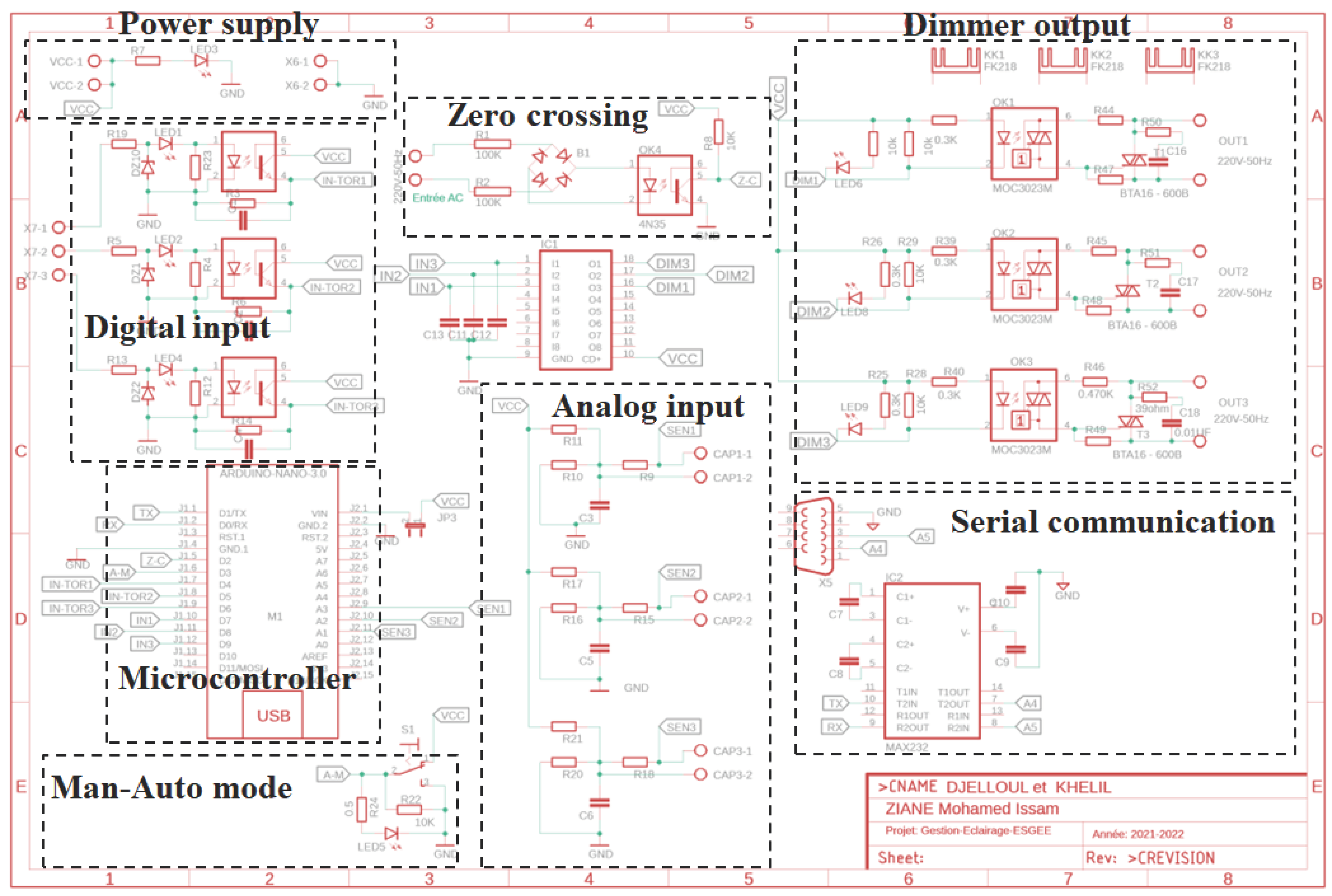
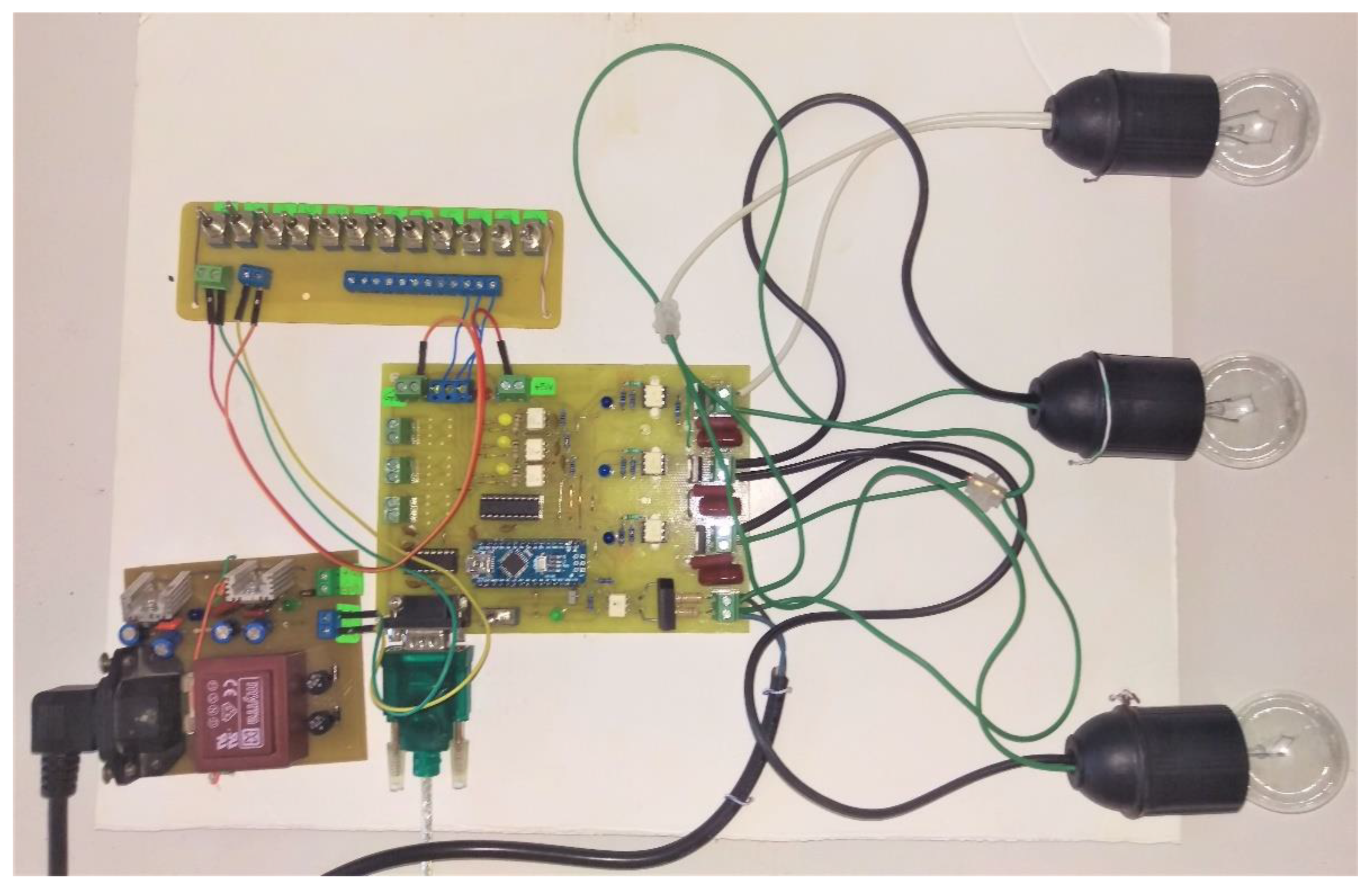
The first part is carried out in two modes, manual and controlled with a graphical interface. The second is processed by a microcontroller, an Aduino nano in our case. As for the third part, it controls three poles via Optotriacs + Triac for full and half lighting. In order to make our light control system, different components were used and a user interface was created. For the realization of our electronic card, and in order to prototype our electronic circuit in a real Printed Circuit Board (PCB), we used the EAGLE PCB software [4] for the design of the printed circuit (Figure 1).
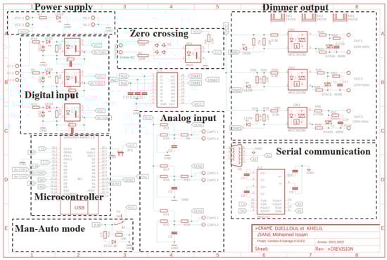
Figure 1.
Electronic diagram of our card produced using EAGLE PCB software.
4. Results and Discussion
4.1. Manual and Command Mode Management
This project is supposed to be a two-mode lighting manager: a controlled mode via the graphical user interface performed with Python, and a manual mode directly organized within the switches. The swinging between the two modes allows for a switch to toggle between the two modes.
The mode change button is essential to launch the manual mode in the case of concern in the controlled mode by Python via the graphical interface.
4.2. Management of Optocoupler Inputs (Digital Inputs)
All the inputs/outputs of a microcontroller are electrically very fragile when it comes to connecting them to the outside world. The inputs–outputs available on the Arduino card must be handled with great care. Our idea was to use galvanic isolation between the inputs of the microcontroller and the outside environment. In other words, there will be no electrical connection between the microcontroller and the external devices and the transfer of information will be conducted by light using an electronic component called an Optocoupler.
In this present project, we will operate our light management and control system only on three poles. As we have already mentioned before, there are two modes of operation. The mode controlled by the graphical user interface that does not require Optocoupler inputs, because the microcontroller will be directly controlled by RS232 serial-type communication. The one that requires galvanic isolation is the manual mode. The electronic card of our system will be controlled by three switches, and to avoid any concern related to overvoltage of the inputs, we have protected our electronic card using Optocouplers.
As you can see on the wiring diagram of Figure 1, the three manual control switch inputs are connected to the discrete inputs of the electronic card using the 3-pin connector. In our system, the input of the Optocoupler (diode side) is controlled precisely like an LED. Resistors limit its current to around If =10 mA. LEDs are current flow indicator light-emitting diodes. The Zener diodes are placed for protection against overvoltage. Other resistors are pull down resistors with a fixed state at LOW (LOW state) whose role is to ensure that the output of the Optocoupler (the input of the microcontroller) is at 0 V when the manual override switch is not pressed.
4.3. Output Management with Triac
The outputs for our project are used to operate the three poles, either full or half. For manual mode, we preferred to turn all three poles on (full) or off. For the controlled mode, we are going to use the dimmer principle. A dimmer is an electronic device designed to regulate light output of incandescent and halogen lamps with special dimming ballasts. A light dimmer works by essentially chopping parts out of the AC voltage.
This allows only parts of the waveform to pass to the lamp. The brightness of the lamp is determined by the power transferred to it, so the more the waveform is chopped, the more it dims. The operation of the dimmer is based on the fact that, during a full cycle of an AC waveform, a Triac will only allow a part of the waveform to be delivered to the load (lamp). A first example that comes to mind is to connect one or more LEDs with the associated resistors; for the present microcontroller, the maximum current that a pin configured as an output can provide is only 16 mA and of 50 mA in total for all the IOs. We will therefore have to use a buffer or driver between the output pin and the load we want to connect. It will of course be necessary to choose the type of driver adapted to the load to be controlled. There are different possibilities for adding an output stage depending on what we want to control. For our part, we have chosen to use the famous ULN2803 driver, which is very responsive in controlling logic peripherals. This circuit serves as a power interface between the microcontroller outputs and the Optotriacs. The ULN2803 is an integrated circuit in DI format that contains eight driver circuits capable of circulating 500mA from our 5V power supply and incorporates anti-return diodes, which allows us to drive our three Optotriacs with complete peace of mind. The Triac output is driven by the ULN2803 via the MOC3023 random-phase Triac driver output Optocoupler (Figure 1).
4.4. Zero Crossing Control and Phase Cutting
The zero crossing is directly derived from the rectified mains AC lines—via an Optocoupler of course—and produces a signal every time the wave goes through zero. Because the sine wave first goes through double phased rectification, the zero-crossing signal is sent regardless whether the sinus wave goes up through zero or down through zero. This signal then can be used to trigger an interruption in the microcontroller. The circuit mounted on our electronic board does exactly that. The main 220-Volt voltage is led through two 100k resistors to a bridge rectifier that sends a double phased rectified signal to a 4N35 Optocoupler. The signal of the 4N35 is fed to an interrupt pin in the microcontroller. Opening the Triac after a delay of a number of microseconds starting from the zero crossing therefore gives a predictable level of dimming.
When the voltage is 5 V, the current in the LED allows the conduction of the Optotriac T1 (see datasheet for MOC3023 Optotriac). When T1 is conductive (it behaves almost like a wire), it controls the trigger T2 of the Triac, which controls the main load, like a switch. T1 is not “powerful” enough to drive the main load directly; it only supports 100 mA, which would not satisfy many people. When the control voltage returns to 0 V, the Optotriac remains on until the cancellation of its current. Conduction therefore remains for the rest of the half period.
In this project, only regular incandescent lamps were truly suitable for dimming (Figure 2). It will work with a halogen lamp as well, but it will shorten the life span of the halogen lamp. It will not work with any cfl lamps, unless they are specifically stated to be suited for a dimmer. The same goes for LED lamps. This main load control by Triac and microcontroller can be reproduced in many copies to control several loads.
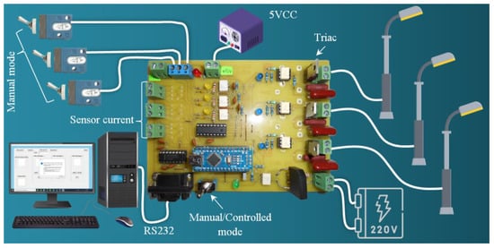
Figure 2.
Lighting management and control project with all necessary elements.
- All the A2 anodes of the power Triacs can be connected together (phase).
- All the bottom terminals of the loads can be connected together (neutral).
4.5. Serial Communication
Generally, a microcontroller works at a TTL of about 0 to 5 V while a computer operates using the standards of RS232 like −25 to +25 V. So interfacing a computer with a microcontroller is not possible without a dual driver/receiver IC. In our project, to connect our microcontroller to the serial we used a MAX232 IC.
The MAX232 IC is widely used for serial communication among microcontrollers-PC. The main function of this integrated circuit is to change the logic levels of TTL/CMOS to RS232 throughout the serial communication process. The circuit was built with a MAX232 IC and four exterior capacitors for producing maximum voltage internally. An Onboard 9-pin female D connects this MAX232 IC to the Serial Port cable. The DB9 Connector connects to the Host for power supply and serial In/Out signals.
4.6. Graphical User Interface
To carry out our practical realization, it was necessary to create a graphic interface in order to control the light in a controlled mode with a dimmer. Therefore, we first asked ourselves the question of how to achieve this and what tools to use. In this project, we used the Python language as the tool that to create the graphical interface.
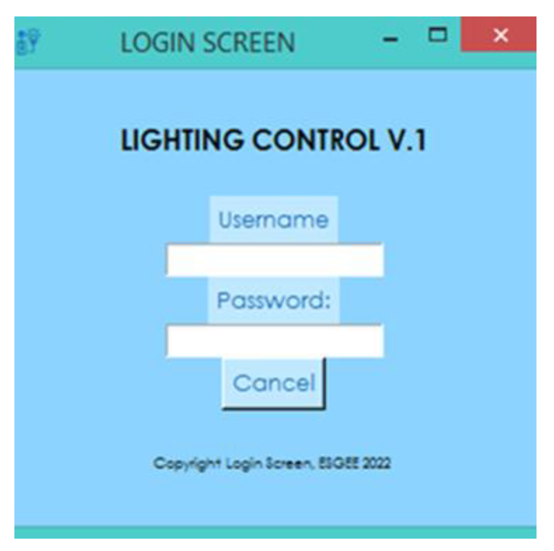
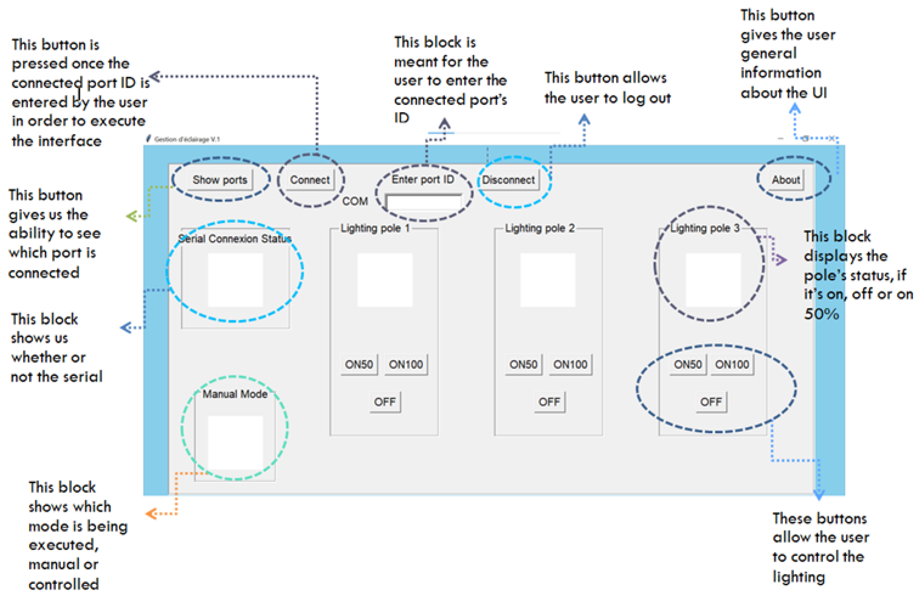
The graphical application of our project has a rather rough design. Without going through more details about the Python code, our graphical interface is divided into two windows: the first is the connection window (Figure 3) and the second is the control interface (Figure 4). On this control interface, there are basically three tabs: connection and serial connection status, control, and operating mode.
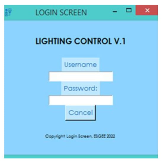
Figure 3.
Login form screenshot using Python Tkinter.
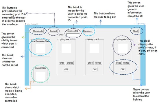
Figure 4.
GUI screenshot using Python Tkinter for our project.
5. Conclusions
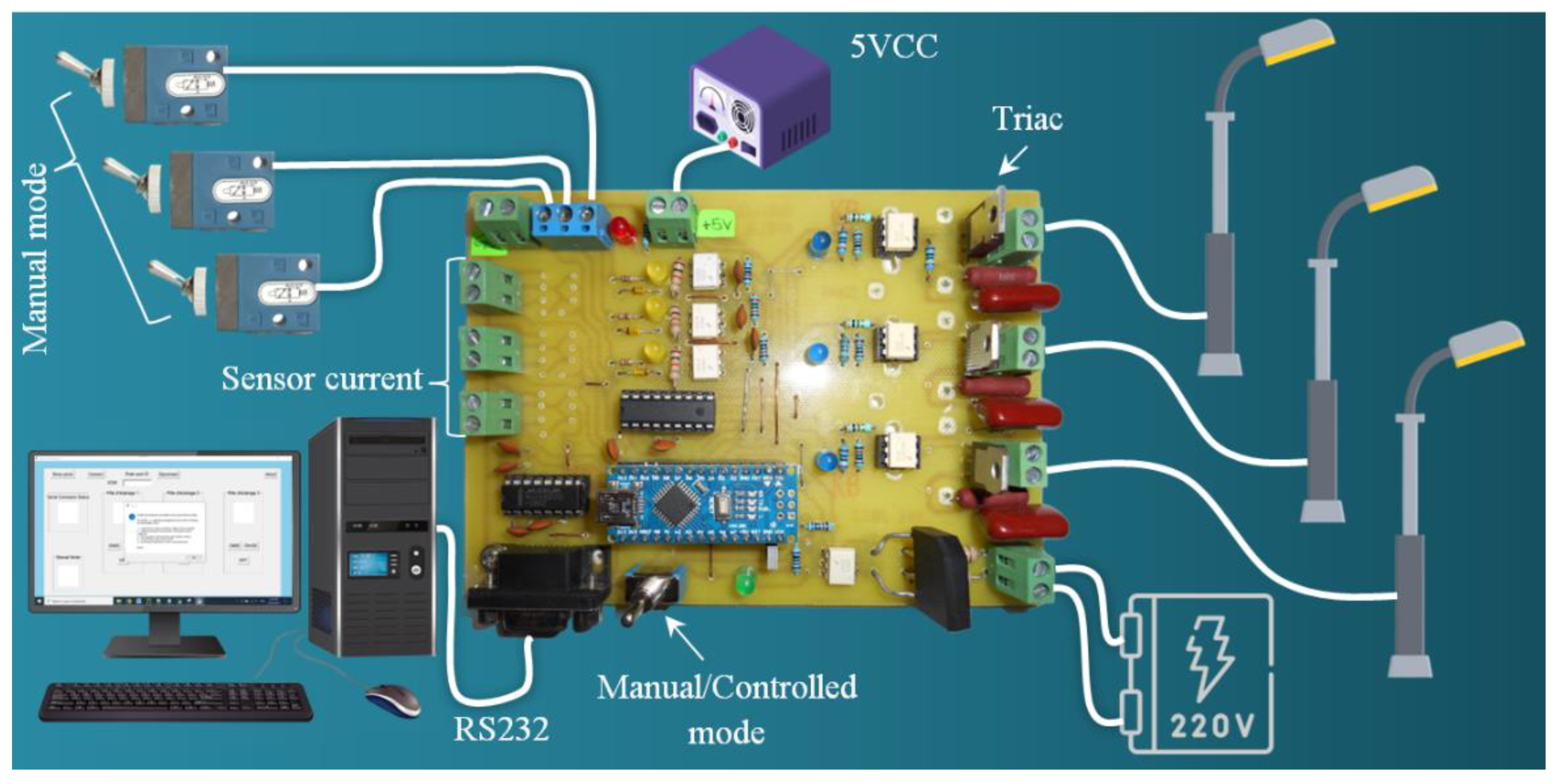
In this project, we presented an approach for the realization of a controlled lighting system (Figure 5), which can be used for a public place or any place. In a public space, good lighting is necessary for the safety and comfort of the users of this space. This is why, today, it has become essential to work to promote more efficient lighting schemes that are respectful of the environment, i.e., less energy consuming.
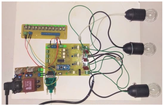
Figure 5.
Final card of our project, connection, and test.
In this work, we implemented a simple lighting system based on a microcontroller, which is the brain and the center of all the equipment used in automatic systems. Furthermore, to carry out our practical realization, we have created a graphical interface that allows the control and management of the lighting.
There are many ideas that could be added to this project. Thus, we can consider some improvements here and there to make this project more and more efficient through a phone application of our system and the integration of current–voltage sensors in order to obtain an overall idea of the consumption of each lighting pole in terms of energy.
Author Contributions
M.I.Z., B.D. and H.K. conceived the project; B.D. and H.K. wrote the manuscript draft; M.I.Z. writing, review, editing, visualization, supervision; G.K.G. formal analysis. All authors have read and agreed to the published version of the manuscript.
Funding
This research received no external funding.
Institutional Review Board Statement
Not applicable.
Informed Consent Statement
Not applicable.
Data Availability Statement
The data presented in this study are available on request from the corresponding authors.
Conflicts of Interest
The authors declare no conflict of interest.
References
- Dwiyaniti, M.; Nitisasmita, K.M.; Tohazen. 2018 1st Workshop on Engineering, Education, Applied Sciences, and Technology. J. Phys. Conf. Ser. 2019, 1364, 012034. [Google Scholar] [CrossRef]
- Alle, A.A. IoT Based Light Control System Using Adaptive Neuro-Fuzzy System; Adama Science and Technology University: Adama, Ethiopia, 2019. [Google Scholar]
- Tamane, S.C.; Dey, N.; Hassanien, A.-E. Security and Privacy Applications for Smart City Development, Volume 308 de Studies in Systems, Decision and Control; Springer Nature: Berlin/Heidelberg, Germany, 2020. [Google Scholar]
- Available online: https://www.autodesk.com/products/eagle (accessed on 2 July 2023).
Disclaimer/Publisher’s Note: The statements, opinions and data contained in all publications are solely those of the individual author(s) and contributor(s) and not of MDPI and/or the editor(s). MDPI and/or the editor(s) disclaim responsibility for any injury to people or property resulting from any ideas, methods, instructions or products referred to in the content. |
© 2023 by the authors. Licensee MDPI, Basel, Switzerland. This article is an open access article distributed under the terms and conditions of the Creative Commons Attribution (CC BY) license (https://creativecommons.org/licenses/by/4.0/).