Abstract
Conventional digital holography uses the technique of combining two coherent light fields and the numerical reconstruction of the recorded hologram leads to the object amplitude and phase information. Despite significant developments in the DH with coherent light, complex field imaging with arbitrary coherent sources is also desired for various reasons. Here, we present a possible experimental approach for holography with incoherent light. In the case of incoherent light, the complex spatial coherence function is a measurable quantity and the incoherent object holograms are recorded as the coherence function. Thus, to record complex spatial coherence a square Sagnac radial shearing interferometer is designed with the phase-shifting approach. The five-step phase-shifting method helps to measure the fringe visibility and the corresponding phase, which jointly represents the complex coherence function. The inverse Fourier transform of the complex coherence function helps to retrieve the object information.
1. Introduction
Digital holography (DH) is a technique of interference of two waves both spatially and temporally coherent [1]. The recorded interference pattern contains both amplitude and phase information which can be further reconstructed by digitally processing the recorded hologram [2,3]. The coherent source is utilized to achieve the interference in the DH, but the coherent imaging system suffers from speckle noise and edge effects [4,5], whereas the incoherent imaging systems both spatially and temporally incoherent, such as broadband or a light emitting diode (LED), do not suffer from speckle noise and also cost-effective. Therefore, over coherent imaging systems incoherent imaging systems are preferred for certain applications.
The interference of incoherent light reflected or emitted from an object result in incoherent digital holograms. Many known methods of recording incoherent holograms are based on the self-interference principle which uses the property that each incoherent source point is acting as an independent scatterer and is self-spatially coherent; hence, it can generate an interference pattern with light coming from its mirror imaged point [6,7,8]. These techniques record the incoherent hologram in the form of intensity patterns. Another way to record an incoherent hologram is through a two-point spatial complex coherence function [9,10]. These methods are based on the van Cittert–Zernike (VCZ) theorem which connects the far-field complex coherence function with the incoherent source intensity distribution.
In this paper, we present an experimental approach to recording an incoherent object hologram based on the VCZ theorem and present some initial results. In the first part of the set up the object information is recorded as a two-point complex spatial coherence function and in the later part a square Sagnac radial shearing interferometer with a five-step phase-shifting technique is designed to obtain the complex coherence function. The digital inverse Fourier transform of complex coherence function helps to retrieve the object information.
2. Principle
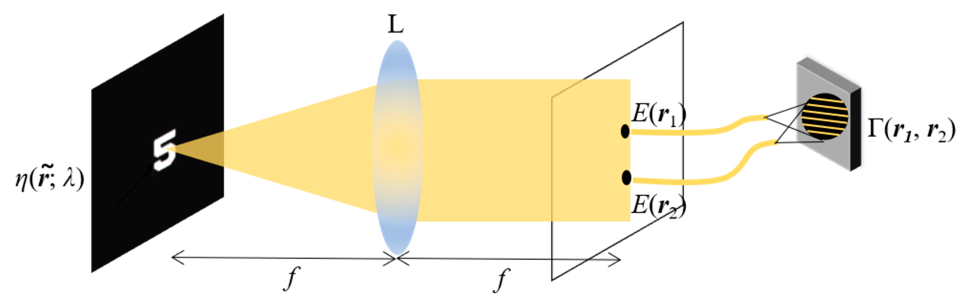
The principle of coherence holography is based on the existing similarity between the VCZ theorem and the diffraction integral. The VCZ theorem connects the coherence function of the incoherent source with its intensity distribution through the Fourier transform relation. Consider a resolution target (number ‘5’) incoherently illuminated by a yellow LED as shown in Figure 1, having spectral scattering density η (; λ) where λ is the mean wavelength of the LED and is the transverse coordinate, respectively. As the source is incoherent each point of LED acts as a random scatterer having instantaneous phase . The spectral component of the field is given by corresponding to λ. The field is Fourier transformed using a lens L having a focal length f and at the Fourier plane, a single realization of the field is represented as
where is the coordinate of Fourier plane.

Figure 1.
Geometry for recording information of spatial coherence function.
The coherence function at the Fourier plane is given by
where the asterisk represents complex conjugate and angle bracket denotes the ensemble average.
From Equation (1), we can write
where is a constant physical quantity having dimensions of length square. As the LED source is spatially incoherent any two points of the source are mutually uncorrelated and hence represented by a two-dimensional (2-D) Dirac–delta function
Equation (3) is now reduced to
In the above equation an integration is also performed over the wavelength range λ as the source is non-monochromatic and have a finite spectral bandwidth. The integral inside the curly bracket represents van Cittert–Zernike theorem.
3. Experiment and Results
Figure 2 shows the experimental setup to record the spatial coherence function. The first part of the setup shows the recording of object information as explained in the previous section. A polarizer P1 is kept at 45° just after the LED source to make the unpolarized light coming from the LED polarized. The field is Fourier transformed using a lens L1 kept at its focal length = 60 mm from the target, number ‘5′. The black dotted line shows the Fourier plane where the spatial coherence function represented by Equation (4) is present. In the later part, a square Sagnac radial shearing interferometer with a telescopic lens system L2 ( = 120 mm) and L3 ( = 125 mm) is designed to measure the coherence function. The incoming field is divided by a polarizing beam splitter with orthogonal polarization states in two parts and between the two oppositely counter-propagating beams one gets magnified with magnification and the other gets demagnified with magnification . Finally, at the output plane shown by blue dotted lines, we get radially sheared copies of the two fields. The output plane parameters are now scaled as and and the coherence function; is now mapped as . The output plane does not fit the CMOS camera area (Thorlabs DCC3240M, imaging area 6.78 mm × 5.43 mm with pixel size 5.3 μm); thus, an imaging lens L4 with focal length = 150 mm is used to demagnify the image such that it fits the camera aperture. At the output, just before the camera, a quarter-wave plate (QWP) is kept at 45° from its fast axis to convert the two linear orthogonal polarization states into right circular and left circular polarization states, respectively. Later, a polarizer P2 is kept and rotated by angle such that it introduces a phase shift between the two incoming beams. Five off-axis interferograms with phase shift 0, π/2, π, 3π/2, and 2π are recorded by giving a tilt using mirror M2 between the two counter-propagating beams. The fringe contrast and corresponding phase can be calculated as mentioned in references [11,12], respectively. Thus, the complex spatial coherence function is built as .
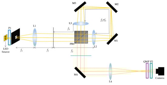
Figure 2.
Experimental set up square Sagnac radial shearing interferometer: P: Polarizer, L: Lens, BS: Beam Splitter, M: Mirror, QWP: Quarter Wave Plate.
Now, to reconstruct the object intensity distribution the spatial coherence function is inverse Fourier transformed.
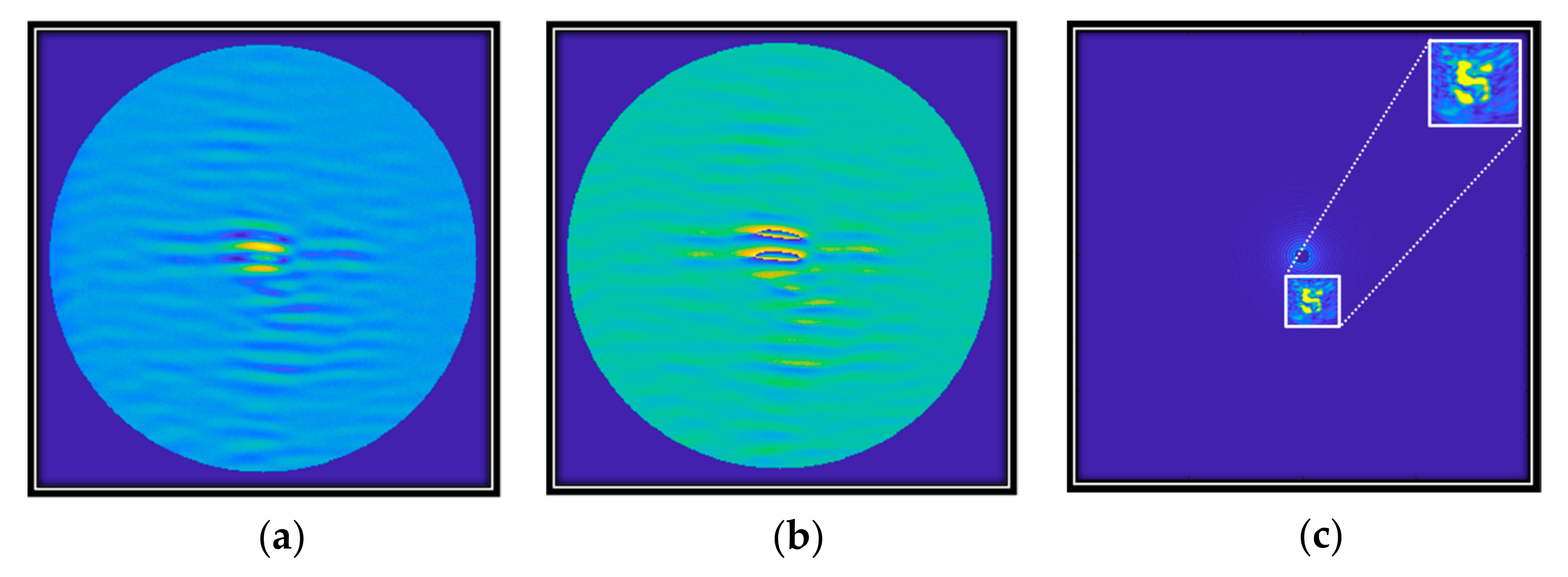
Figure 3 represents the digitally constructed (a) fringe visibility and (b) corresponding phase using the five recorded interferograms and (c) the reconstructed object intensity distribution showing the information of number ‘5′.
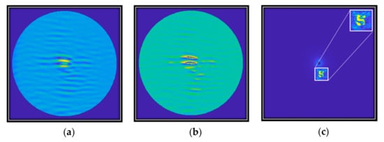
Figure 3.
Digitally constructed coherence function (a) fringe visibility, (b) corresponding phase, and (c) reconstructed object intensity distribution.
4. Conclusions
We have presented an experimental method using shearing for holography with an incoherent source. The object information is recorded in the form of a complex spatial coherence function based on the principle of van Cittert–Zernike theorem and later it is analyzed using a Sagnac radial shearing interferometer with the five-phase shifting algorithm. The object information is computationally acquired on inverse Fourier transform.
Author Contributions
A.G.: Conceived the idea, Investigation, Writing manuscript, Methodology, Experimental Design. A.T.S.: Experimental Design. D.N.N.: Ideas, Revision and Editing, Supervision. C.S.N.: Editing and revision of the manuscript. R.S.: Editing and revision of the manuscript. R.K.S.: Ideas, Formulation of research goals, Revision and Editing, Funding acquisition, Supervision. All authors have read and agreed to the published version of the manuscript.
Funding
This work is supported by the Board of Research in Nuclear Sciences (BRNS––Grant No. 58/14/04/2021-BRNS/37092).
Institutional Review Board Statement
Not applicable.
Informed Consent Statement
Not applicable.
Data Availability Statement
Data underlying the results presented in this paper are not publicly available at this time but may be obtained from the authors upon reasonable request.
Acknowledgments
Akanksha Gautam would like to acknowledge support from DST-INSPIRE (IF180930).
Conflicts of Interest
The authors declare no conflict of interest.
References
- Gabor, D. A new microscopic principle. Nature 1948, 161, 777–778. [Google Scholar] [CrossRef]
- Hendry, D. Digital Holography: Digital Hologram Recording, Numerical Reconstruction and Related Techniques; Schnars, U., Jueptner, W., Eds.; Springer: Berlin/Heidelberg, Germany, 2005; ISBN 354021934-X. [Google Scholar]
- Lee, W.H. Sampled Fourier transform hologram generated by computer. Appl. Opt. 1970, 9, 639–643. [Google Scholar] [CrossRef]
- Considine, P.S. Effects of coherence on imaging systems. J. Opt. Soc. Am. 1966, 56, 1001–1009. [Google Scholar] [CrossRef]
- Mills, J.P.; Thompson, B.J. Effect of aberrations and apodization on the performance of coherent optical systems. II. Imaging. J. Opt. Soc. Am. 1986, 3, 704–716. [Google Scholar] [CrossRef]
- Rosen, J.; Brooker, G. Digital spatially incoherent Fresnel holography. Opt. Lett. 2007, 32, 912–914. [Google Scholar] [CrossRef] [PubMed]
- Vijayakumar, A.; Kashter, Y.; Kelner, R.; Rosen, J. Coded aperture correlation holography—A new type of incoherent digital holograms. Opt. Express 2016, 24, 12430–12441. [Google Scholar] [CrossRef] [PubMed]
- Wu, J.; Zhang, H.; Zhang, W.; Jin, G.; Cao, L.; Barbastathis, G. Single-shot lensless imaging with fresnel zone aperture and incoherent illumination. Light Sci. Appl. 2020, 9, 53. [Google Scholar] [CrossRef] [PubMed]
- Naik, D.N.; Ezawa, T.; Singh, R.K.; Miyamoto, Y.; Takeda, M. Coherence holography by achromatic 3-D field correlation of generic thermal light with an imaging Sagnac shearing interferometer. Opt. Express 2012, 20, 19658–19669. [Google Scholar] [CrossRef] [PubMed]
- Naik, D.N.; Pedrini, G.; Osten, W. Recording of incoherent-object hologram as complex spatial coherence function using Sagnac radial shearing interferometer and a Pockels cell. Opt. Express 2013, 21, 3990–3995. [Google Scholar] [CrossRef] [PubMed]
- Roy, M.; Svahn, P.; Cherel, L.; Sheppard, C.J. Geometric phase-shifting for low-coherence interference microscopy. Opt. Lasers Eng. 2002, 37, 631–641. [Google Scholar] [CrossRef]
- Hariharan, P.; Oreb, B.F.; Eiju, T. Digital phase-shifting interferometry: A simple error-compensating phase calculation algorithm. Appl. Opt. 1987, 26, 2504–2506. [Google Scholar] [CrossRef] [PubMed]

Disclaimer/Publisher’s Note: The statements, opinions and data contained in all publications are solely those of the individual author(s) and contributor(s) and not of MDPI and/or the editor(s). MDPI and/or the editor(s) disclaim responsibility for any injury to people or property resulting from any ideas, methods, instructions or products referred to in the content. |
© 2023 by the authors. Licensee MDPI, Basel, Switzerland. This article is an open access article distributed under the terms and conditions of the Creative Commons Attribution (CC BY) license (https://creativecommons.org/licenses/by/4.0/).