Abstract
Polarization has a profound impact on image quality and visual perception. For instance, polarization provides a new perspective on seeing an object which is otherwise obscured, low contrast or not measurable by conventional imaging methods. In this paper, we discuss a possible extension of the digital holography (DH) to the polarization domain, and the technique is referred to as digital polarization holography (DPH). The basic principle of the DPH is described and some of our recent contributions on quantitative vectorial imaging are covered. We also discuss and highlight the potential of combining speckle field illumination with DPH for high-resolution vectorial imaging.
1. Introduction
Holography uses the principle of interference to record and reconstruct complex valued objects. The availability of high-quality detectors and computational facilities has popularized holography through digital holography (DH), where a hologram is digitally recorded and a reconstruction of the hologram is implemented by numerical methods [1]. DH provides a quantitative information of the complex fields, i.e., amplitude and phase. This is advantageous in the context of real-time live quantitative imaging, digital depth focusing, 3D, and label-free nondestructive imaging. The availability of array detectors and reconstruction algorithms have further revolutionized holography. Different DH schemes have been developed, and significant among them are in-line, off-axis, and phase-shifting holography. Off-axis holography requires angularly separated object and reference beams in an interferometric design, and this geometry avoids the twin image problem in the reconstruction. A concept of preserving information in the interference fringes has also been tested for self-luminous or incoherent objects. Significant techniques among the incoherent holography are coherence holography [2] and Fresnel incoherent correlation holography (FINCH) [3]. Coherence holography is an unconventional approach, wherein the complex valued object is reconstructed as a spatial distribution of the complex coherence function. In another development, DH methods are used to image 2D and 3D objects located behind the random scattering medium [4,5,6].
DH has emerged as a unique technique to quantitatively measure the wavefront of light. A DH combined with microscopy, called digital holographic microscopy (DHM) is nowadays widely used for a wide range of applications [1]. However, a complete description of the wavefront needs the inclusion of the polarization vector in its measurement and analysis [7]. Polarization analysis is important in fields such as stress analysis, bio-medical imaging, chemistry and so on. Polarization states, a significant parameter to describe light matter interactions, have been critical and significant in contrast enhancement, and highlight specific cell structures which are otherwise missing in the scalar imaging. Therefore, polarization imaging is considered to be a promising and futuristic tool, as it is capable of revealing the order at a molecular scale that is usually hidden to the conventional microscopes. Lohman was the first to propose the issue of the total recording and reconstruction of the wavefront by including the polarization vector in the wavefront reconstruction [7]. The extension of holography to the polarization domain is possible by recording and reconstructing two holograms of the orthogonal polarization components [8,9,10,11,12]. In order to expand polarization holography to the light with arbitrary coherence, it is desirable to examine the interference using the Stokes parameters of the light [9,10]. A practical challenge in polarization holography is the recording and reconstruction of four holograms which correspond to all four Stokes parameters. This challenge has been attempted by using random scattering as a real-time recording plane and reconstructing the polarization vector by two-point complex correlations of the random light field. Polarization imaging of three-dimensional imaging using phase-shifting holography is also possible.
In this paper, we discuss polarization interference fringes and their role in the recording and reconstruction of the complete wavefront. To demonstrate the usefulness of the polarization fringes in the quantitative and spatially resolved imaging, beyond conventional DH, we perform the recording and reconstruction of the polarization holograms with a generic light source of various correlations. We discuss different experimental designs of digital polarization holography (DPH) and some of our recent contributions on quantitative vectorial imaging. A new approach in the polarization domain of holograph, called speckle-field digital polarization holographic microscopy (SDPHM) is also discussed. The idea is to use a random pattern (rather than a uniform field) for illumination of the sample and thereby recover the high-resolution polarization features in comparison to the scalar DPH.
2. Polarization Holograms
2.1. Digital Polarization Holography
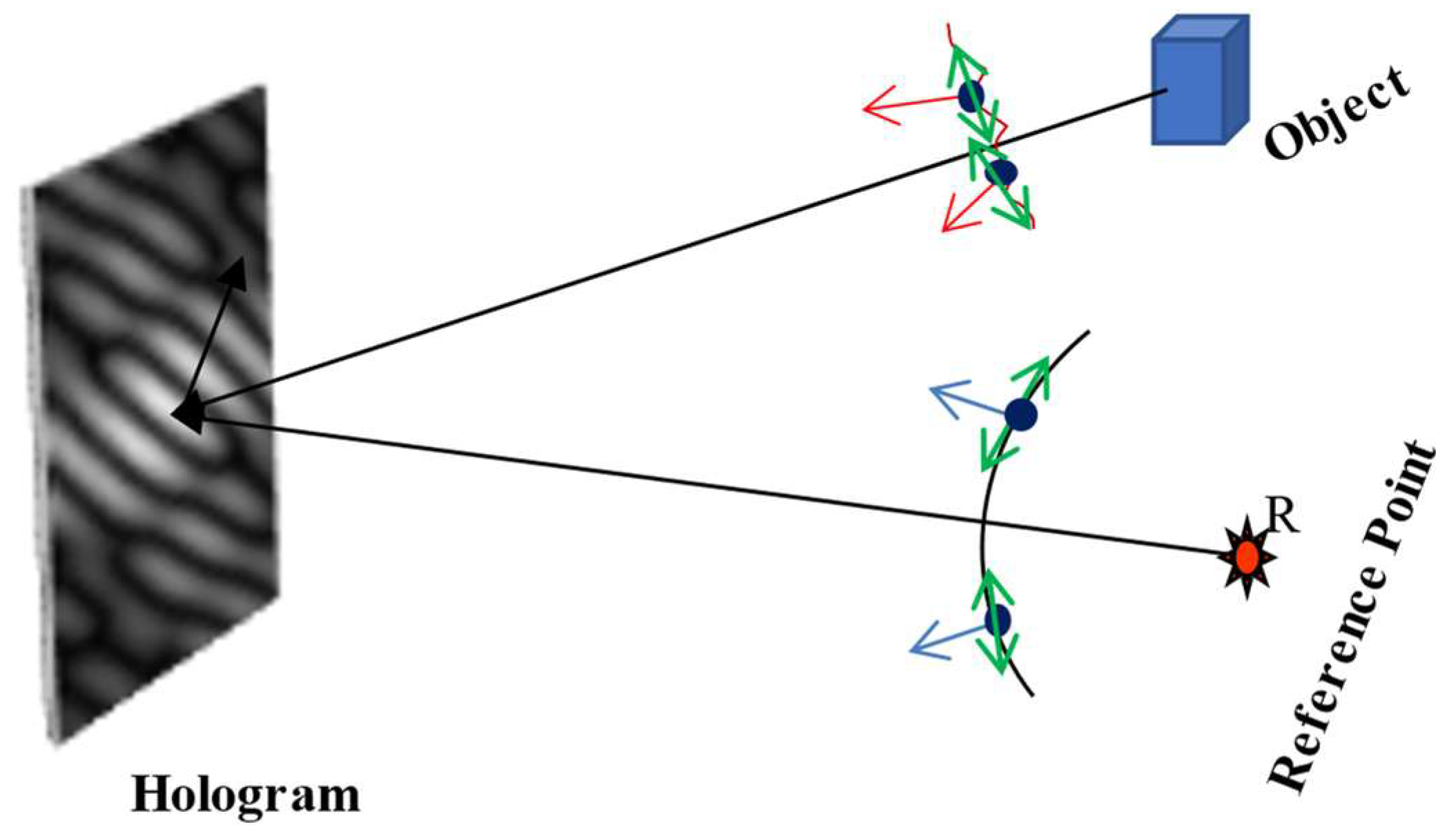
Consider the recording geometry represented in Figure 1. This figure shows the recording of a hologram by interference of the waves emerging from two sources, i.e., the object and reference. The vectorial nature of the light waves, on the plane and vertical to the plane, are represented by a green arrow and black circle. Here, the arrow represents the polarization vector on the plane and black circle represents a polarization vector perpendicular to this plane. The propagation of the light field from the source to the observation is represented as
where and represent a realization of the object field at the observation and source plane, respectively, and represents the orthogonal polarization components; and is the propagation kernel to accommodate diffraction from the source position to the spatial position at the observation plane. A reference beam is considered to be uniform with a linear phase of spatial frequency .

Figure 1.
A schematic diagram to represent recording of the hologram.
2.2. Recording and Reconstruction of the Polarization Hologram
A single realization of orthogonally polarized components, at the observation plane, are represented as
Stokes fringes can be obtained from the orthogonal polarization components as
where < . > angular bracket represent the ensemble average to evaluate the statistical properties of the light. Four Stokes parameters encode coherence-polarization features of the sources at the recording plane. The first Stokes parameter in Equation (5), i.e., represents the intensity and corresponds to the conventional hologram recording. Either a combination of and or and is sufficient to reconstruct the full field of the object in a coherent recording. A detailed discussion on recording and reconstruction of the Stokes hologram can be found in Refs. [9,10].
3. Experimental Design and Implementation
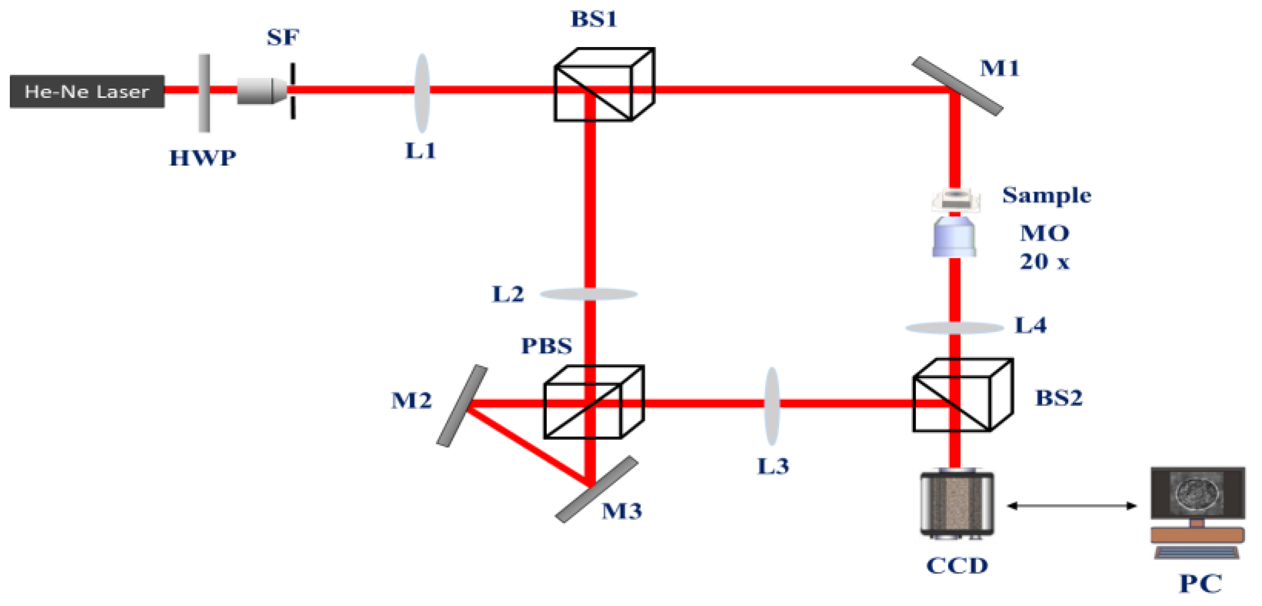
In order to consider the recording and reconstruction of holograms from the coherent and fully polarized source, we confine it to the first two Stokes parameters and use holograms of the orthogonally polarized components, i.e., and . An experimental scheme to simultaneously record these two holograms are shown in Figure 2. A specially designed Mach–Zehnder type polarization interferometer equipped with a triangular Sagnac geometry is used to simultaneously record the orthogonal polarization components. A collimated diagonally polarized coherent beam is split into two copies by a beam splitter (BS1). A beam, transmitted by BS1 and folded by the mirror M1, illuminates the sample. This object beam is imaged at the camera plane through the BS2. On the other hand, a beam reflected by the BS1 works enters into a triangular Sagnac interferometer assisted with a telescopic lens assembly (L2 and L3) to generate a distinguishable orthogonally polarized reference beam. A polarization beam splitter (PBS) splits into counter propagating orthogonally polarized components. The mirrors M2 and M2 introduce spatial separation in the orthogonally polarized components at the back focal plane of lens L2 which is also a front focal plane of lens L3. Thus, the orthogonally polarized components, coming out of the triangular Sagnac geometry, gain distinguishable linear phases at the back focal plane of lens L3 which overlaps with the detector plane. The angular multiplexed reference beams is a significant feature of our experimental design and has been utilized for single-shot polarization imaging [11] and Jones matrix microscopy [13]. These reference beams interfere with the object beam and a hologram is recorded by the charge coupled device (CCD). The intensity, recorded by the CCD, is represented as
where and are reference beams for the x and y polarization components, respectively. Orthogonal polarization components of the object field are represented as and .

Figure 2.
An experimental setup to record polarization hologram.
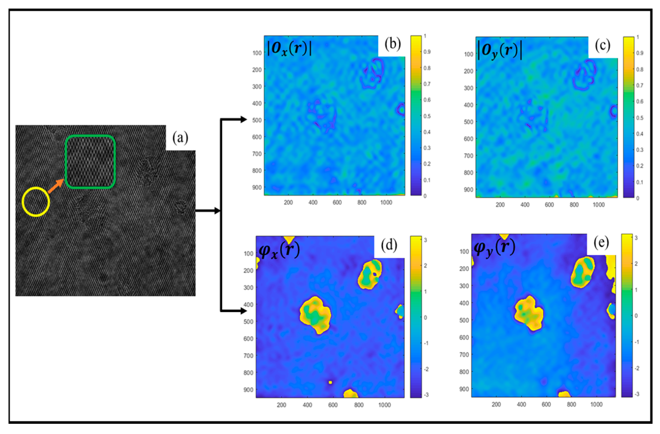
For demonstration purposes, we present an interference pattern of the birefringence object in Figure 2. A mesh structure in the interference pattern, as highlighted in the inset, appears due to distinguishable carrier frequencies of the orthogonally polarized reference beams. This scheme is very important for recording and reconstructing the spatially varying polarization of the object from a single hologram recording [11]. This recorded hologram is subjected to digital Fourier fringe analysis to reconstruct the complex fields of the orthogonally polarized components, and results are shown on the right hand side in Figure 3.

Figure 3.
Reconstruction of complex fields of the orthogonal polarization components from a recorded hologram. (a) represents the digitally recorded hologram. (b,c) represent amplitude distributions of the orthogonal polarization components. Corresponding phase distributions are shown in (d,e).
4. Challenges and Opportunities
In general, all four Stokes fringes are desired for a generic imaging application. An intensity fringe is one of the four Stokes fringes. Thus, the recording and reconstruction of all four fringes may require multiple measurements by varying the polarization optics or using the polarization sensitive recording medium. A challenge of multiple-step recording can be addressed by using a polarization-sensitive detector or using the random scattering medium as a real-time recording medium with correlation-based reconstruction. The importance of the Stokes fringes in polarization imaging can be highlighted by the example of interference between the orthogonal polarization components which is not possible to observe using conventional digital holography. Considering an off-axis object with a horizontally polarized transmittance, i.e., , and reference with a vertical polarization, i.e., , the first two Stokes parameters at the recording plane, i.e., and , are made of only non-modulating terms and no interreference appears in these fringes as expected from the scalar theory. On the other hand, the Stokes fringes and preserve a spatial carrier frequency introduced by the cross-modulations between the off-axis object and the on-axis reference source [10]. The recording and digital reconstruction of the polarization holograms have also offered a new opportunity to use speckle field illumination for high-resolution polarization imaging, and the technique is referred as speckle-field digital polarization holographic microscopy (SDPHM) [13]. A digitally generated speckle pattern illumination in the SDPHM offers a new opportunity to explore high resolution polarization imaging.
5. Conclusions
The possible extension of digital holography to the polarization domain is discussed and some of our recent contributions are briefly discussed in this paper. A special emphasis is given to the recording and reconstruction of complete and spatially resolved polarimetric features from a single hologram.
Funding
This work is supported by the Science and Engineering Research Board (SERB) India CORE/2019/000026 and the Department of Biotechnology (DBT) Grant No. BT/PR35587/MED/32/707/2019.
Institutional Review Board Statement
Not applicable.
Informed Consent Statement
Not applicable.
Data Availability Statement
Not applicable.
Acknowledgments
This paper is based on research contributions of former and present lab members. R. K. Singh acknowledges support from the IIT (BHU) and different funding agencies.
Conflicts of Interest
The author declares no conflict of interest.
References
- Schnars, U.; Jueptner, W. Digital Holography, 1st ed.; Springer: Berlin/Heidelberg, Germany, 2005. [Google Scholar]
- Takeda, M.; Wang, W.; Duan, Z.; Miyamoto, Y. Coherence holography. Opt. Express 2005, 13, 9629–9635. [Google Scholar] [CrossRef] [PubMed]
- Rosen, J.; Brooker, G. Digital spatially incoherent Fresnel holography. Opt. Lett. 2007, 32, 912–914. [Google Scholar] [CrossRef] [PubMed]
- Naik, D.N.; Singh, R.K.; Ezawa, T.; Miyamoto, Y.; Takeda, M. Photon correlation holography. Opt. Express 2010, 19, 1408–1421. [Google Scholar] [CrossRef] [PubMed]
- Singh, R.K.; Vinu, R.V.; Sharma, A. Recovery of complex valued objects from two-point intensity correlation measurement. Appl. Phys. Lett. 2014, 104, 111108. [Google Scholar] [CrossRef]
- Singh, R.K.; Sharma, A.M.; Das, B. Quantitative phase contrast imaging through a scattering medium. Opt. Lett. 2014, 39, 5045–5057. [Google Scholar] [CrossRef] [PubMed]
- Lohmann, A.W. Reconstruction of vectorial wavefronts. Appl. Opt. 1965, 4, 1667–1668. [Google Scholar] [CrossRef]
- Colomb, T.; Dahlgren, P.; Beghuin, D.; Cuche, E.; Marquet, P.; Depeursinge, C. Polarization imaging by use of digital holography. Appl. Opt. 2002, 41, 27–37. [Google Scholar] [CrossRef] [PubMed]
- Singh, R.K.; Naik, D.N.; Itou, H.; Miyamoto, Y.; Takeda, M. Stokes holography for recording and reconstructing objects using polarization fringes. Proc. SPIE 2011, 8082, 808209. [Google Scholar]
- Singh, R.K.; Naik, D.N.; Itou, H.; Miyamoto, Y.; Takeda, M. Stokes holography. Opt. Lett. 2012, 37, 966–996. [Google Scholar] [CrossRef] [PubMed]
- Sreelal, M.M.; Vinu, R.V.; Singh, R.K. Jones matrix microscopy from a single-shot intensity measurement. Opt. Lett. 2017, 42, 5194–5197. [Google Scholar] [CrossRef] [PubMed]
- Singh, D.; Singh, R.K. Lensless Stokes holography with the Hanbury Brown-Twiss approach. Opt. Express 2018, 26, 10801–10812. [Google Scholar] [CrossRef] [PubMed]
- Vinu, R.V.; Chen, Z.; Pu, J.; Otani, Y.; Singh, R.K. Speckle-field polarization holographic microscopy. Opt. Lett. 2019, 44, 5711–5714. [Google Scholar] [CrossRef] [PubMed]
Disclaimer/Publisher’s Note: The statements, opinions and data contained in all publications are solely those of the individual author(s) and contributor(s) and not of MDPI and/or the editor(s). MDPI and/or the editor(s) disclaim responsibility for any injury to people or property resulting from any ideas, methods, instructions or products referred to in the content. |
© 2023 by the author. Licensee MDPI, Basel, Switzerland. This article is an open access article distributed under the terms and conditions of the Creative Commons Attribution (CC BY) license (https://creativecommons.org/licenses/by/4.0/).