Proceeding Paper

Combination Process of a Pneumatic Artificial Muscle and a Fiber Optical Sensor System †

Graduate School of Natural Science and Technology, Okayama University, Okayama 7008530, Japan
*
Author to whom correspondence should be addressed.
Presented at the 9th International Electronic Conference on Sensors and Applications, 1–15 November 2022; Available online: https://ecsa-9.sciforum.net/.
Eng. Proc. 2022, 27(1), 86; https://doi.org/10.3390/ecsa-9-13290
Published: 1 November 2022

Abstract

:
A McKibben artificial muscle is a typical soft actuator, and it features flexibility, lightweight, and low cost. It consists of a rubber tube and a sleeve which is woven with spiral fibers, and contracts axially by applying pneumatic pressure to the rubber tube. We have developed the combination structure of the McKibben artificial muscle and the optical fiber which works as a contractile displacement sensor. The optical fiber can be braided into the sleeve which is the necessary component of the artificial muscle, which means that the optical fiber works as not only the sensor element but also the actuator element. In the previous sensor system, the light-receiving part (photo IC diode) and the light-emitting part (LED) were located at the base and tip sides of the artificial muscle, respectively. This configuration has a limitation in applications and the possibility of electrical line troubles. In this report, the LED and the photo IC diode are arranged at the base end of the artificial muscle by improving the fabrication process. Through the process, the optical fiber from the base can be returned to the base again via the tip, and the LED and photo IC diode can be located at the base side of the artificial muscle. Experimentally, the relation between the sensor output and contractile displacement of the artificial muscle was confirmed.

1. Introduction

The McKibben artificial muscle is known as a soft actuator that is flexible, light-weight, and has a high power-to-weight ratio and has been actively studied as the actuator for medical devices and support equipment due to its highly safe property for humans. The McKibben artificial muscle consists of a rubber tube around which sleeve fibers are wound in a spiral shape. By sealing one end and applying air pressure from the other end to the rubber tube, the sleeve fibers act as a pantograph mechanism, resulting in the artificial muscle contracting axially.
For controlling the artificial muscle, an external sensor to measure the contractile displacement is required, and general sensors are rigid, heavy, and large. In addition, they must be assembled to the artificial muscle after fabricating the artificial muscle. Therefore, they detract from the advantages of the McKibben artificial muscle itself, and the fabrication process becomes complex. To solve these problems, the smart structures in which the fiber sensors are used as the sleeve fibers of the artificial muscle have been developed [1,2,3,4,5,6]. We have used optical fiber for sensing the displacement of the artificial muscle, and indicated the possibility [4,5]. One of the advantages of using optical fiber is fewer external electric-magnetic noise factors.
In the previous report [4,5], the light emitting element (LED) was located on the tip of the artificial muscle, and the light receiving element (photo IC diode) was on the base side of the artificial muscle, respectively and separately as shown in Figure 1. In addition, wiring to apply the voltage to the LED was needed from the base side to the tip. When considering a practical application, this configuration may make the application system more complicated structurally. Therefore, in this study, we redesign the arrangement of the LED to be on the base side. As this improvement, the optical fiber which is wrapped around a rubber tube from the base must be turned back to the base via the tip. For making this configuration, we modified the braiding process. Experimentally the relation between the displacement of the artificial muscle and the output of the optical fiber sensor was confirmed.

2. Materials and Methods

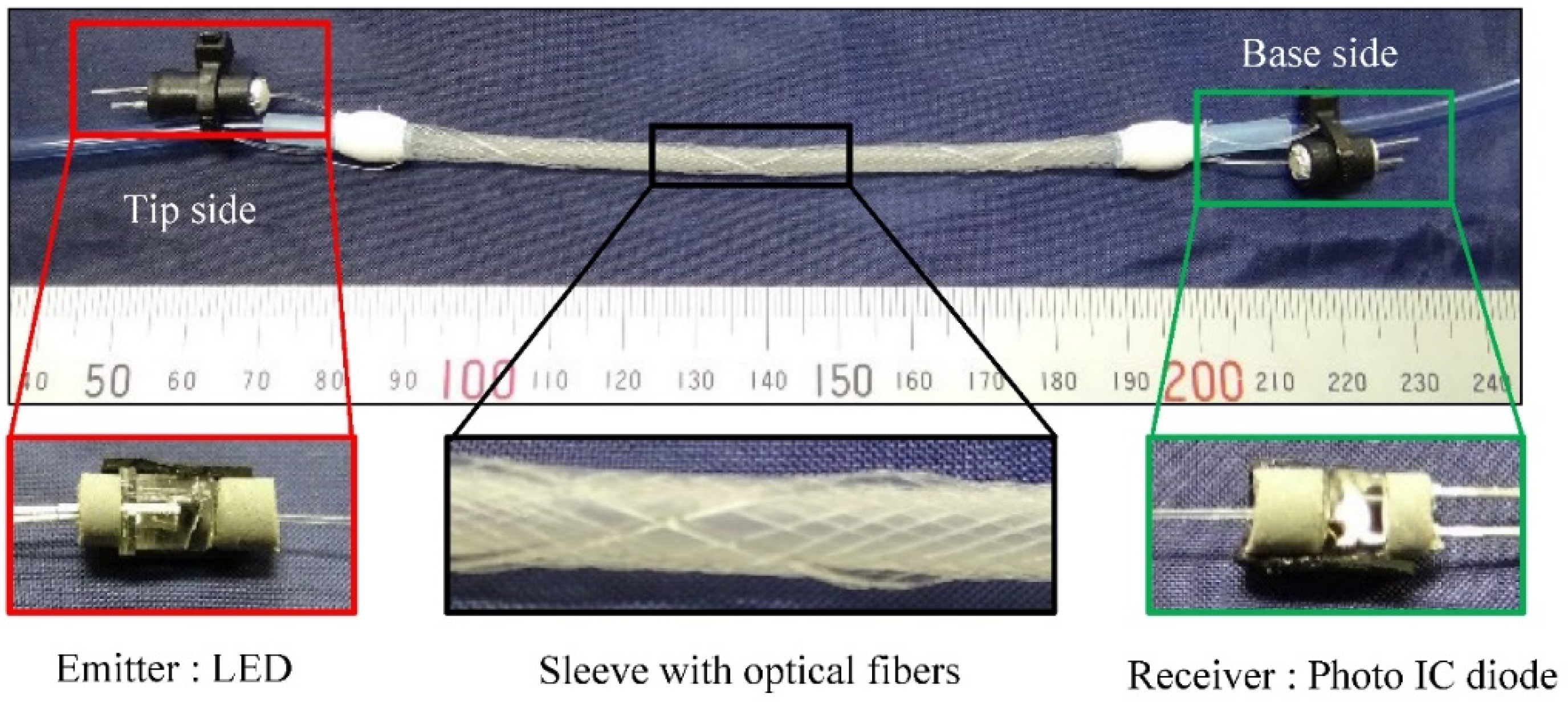
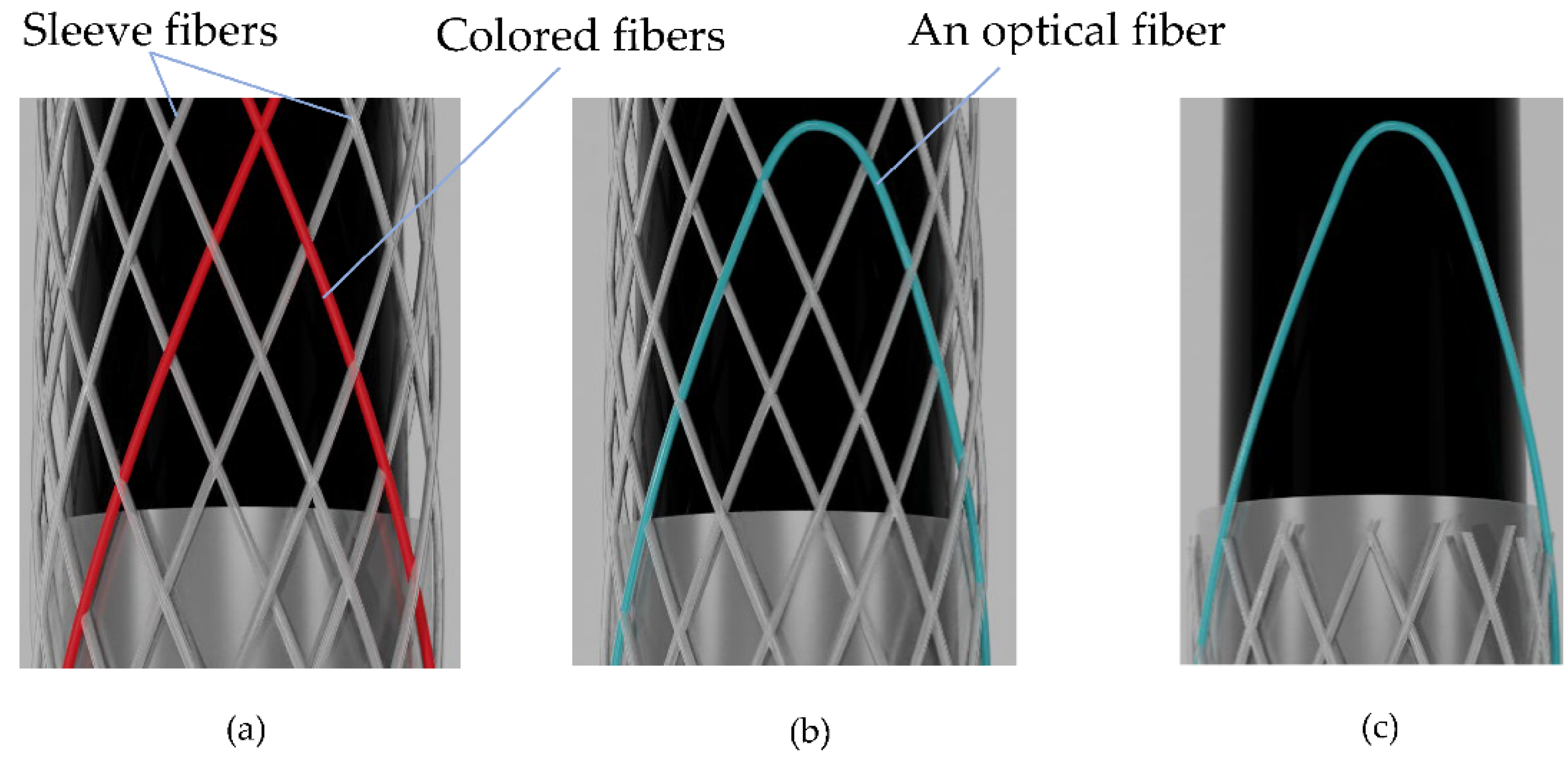
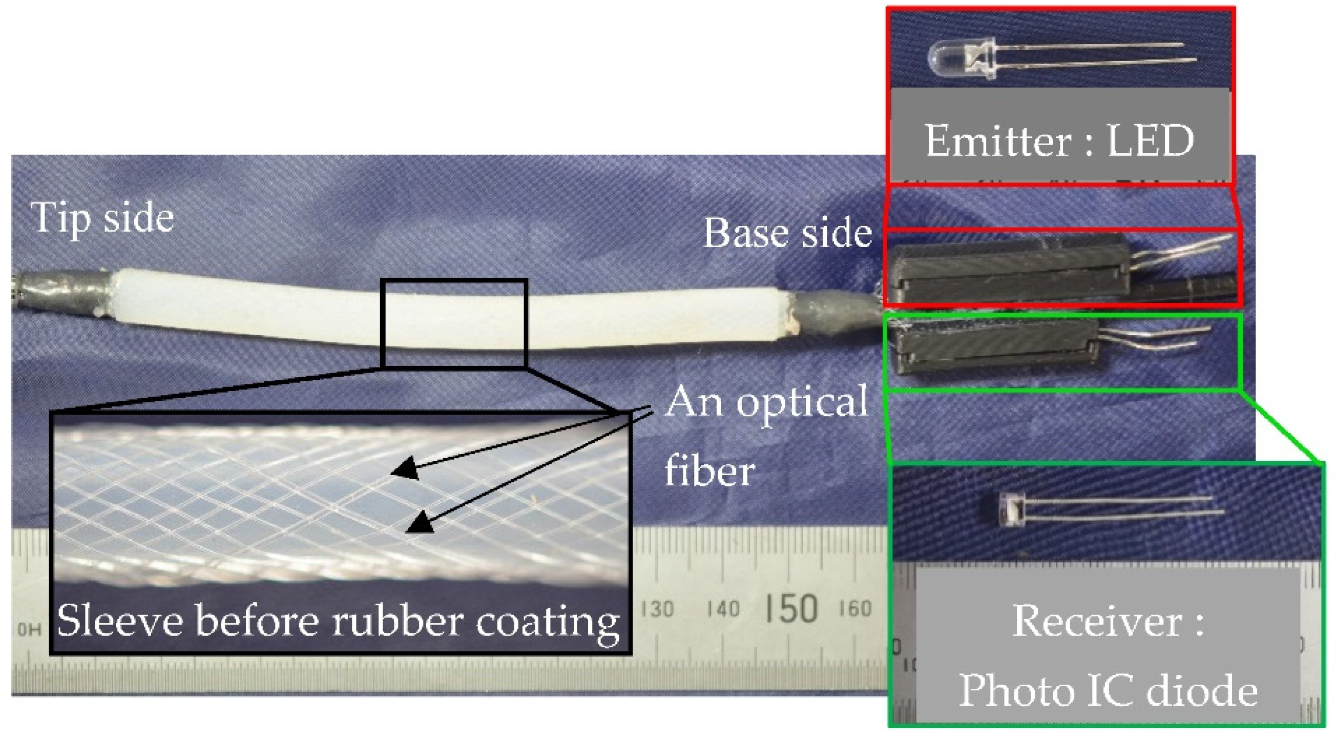
2.1. Improved Structure of the Artificial Muscle with the Optical Fiber

Figure 2 shows the image of the artificial muscle with optical fiber having the LED and the photo IC diode on one side (base side). The silicone rubber tube has sleeve fibers spirally woven around it to form a sleeve. An optical fiber is woven with normal fibers together forming a helix. By returning the optical fiber at the tip, both ends of the optical fiber are located at the base side. Then the LED and the photo IC diode can be placed on the base side. The curvature of the optical fiber changes as a contraction of the artificial muscle. By this curvature change, the amount of light leaking from the optical fiber changes. Therefore, the displacement of the artificial muscle can be estimated by measuring the change in the amount of light. In this study, the photo IC diode was connected in series to a resistor, and the voltage output of the resistor was used as the sensor output.

2.2. Production Method

The artificial muscle was fabricated using a braiding machine shown in Figure 3. The braiding machine has 32 bobbins, 16 of which rotate clockwise and the other 16 rotate counterclockwise. By this rotation, a sleeve with the fibers in a spiral pattern around the silicone tube was formed.
For making the structure shown in Figure 2. Two bobbins, one rotating clockwise, and the other rotating counterclockwise, are selected and colored fibers are set to distinguish between other fibers. Then the sleeve is braided about 10 mm around the rubber tube as shown in Figure 4a. After that, two colored fibers are replaced by one optical fiber forming a loop shape, as shown in Figure 4b. Then the braiding process restarts and the process is continued by any length of the artificial muscle, and the unnecessary fibers around the tip are cut off as shown in Figure 4c. Finally, the whole structure was coated in silicone rubber for avoiding the shifting of the fibers during actuation, and the LED and the photo IC diode are attached on the base side.

3. Results and Discussion

Figure 5 shows the fabricated artificial muscle with optical fiber. The length of the actual driving part is 100 mm and the outer diameter is 6.5 mm including the rubber coating. The LED and the photo IC diode, which are incorporated into the resin boxes for preventing leakage and incidence of light, are arranged on the base side together.
The basic characteristics of the artificial muscle were measured. In order to keep the artificial muscle in a straight line and to drive it stably, a weight of 1.8 N was added to pull it. The length of the artificial muscle changes from 100 mm to 85 mm when the pneumatic pressure of 300 kPa is applied. Figure 6 shows the relation between the length of the artificial muscle and the sensor output. The linear relation between the length of the artificial muscle and the sensor output can be found. The results of the Linear approximation performed on this data show that the value of the coefficient of determination is 0.990, indicating that the approximate straight line agrees very well with the data. In Figure 6, R² represents the coefficient of determination of the Linear approximate line.

4. Conclusions

In this study, for improving the practical usability of the artificial muscle with the optical fiber, the light emitting part (LED) and the light receiving part (photo IC diode) are located on the base side of the artificial muscle. To realize this configuration, the fabrication process using the braiding machine was changed partially. Experimentally, we confirmed the linear relation between the length of the artificial muscle and the sensor output.

Author Contributions

Conceptualization, Y.Y. and S.W.; methodology, Y.Y.; validation, W.T. and K.I.; data curation, K.I.; writing—original draft preparation, Y.Y.; writing—review and editing, S.W. and W.T.; T.K., and D.Y.; funding acquisition, S.W. All authors have read and agreed to the published version of the manuscript.

Funding

This research was partially supported by Grants-in-Aid for Scientific Research (Grant Number 20K04240) by the Japan Society for the Promotion of Science.

Institutional Review Board Statement

Not applicable.

Informed Consent Statement

Not applicable.

Data Availability Statement

Not applicable.

Conflicts of Interest

The authors declare no conflict of interest.

References

  1. Felt, W.; Chin, K.Y.; Remy, C.D. Contraction Sensing with Smart Braid McKibben Muscles. IEEE ASME Trans. Mechatron. 2016, 3, 1201–1209. [Google Scholar] [CrossRef] [Green Version]
  2. Wakimoto, S.; Misumi, J.; Suzumori, K. New Concept and Fundamental Experiments of a Smart Pneumatic Artificial Muscle with a Conductive Fiber. Sens. Actuator A Phys. 2016, 250, 48–54. [Google Scholar] [CrossRef]
  3. Kogawa, S.; Wakimoto, S.; Kanda, T.; Omura, K.; Ando, K. Establishment of fabrication process for smart artificial muscles with the inductance sensor. J. Jpn. Fluid Power Syst. Soc. 2020, 51, 25–31. (In Japanese) [Google Scholar] [CrossRef]
  4. Kogawa, S.; Wakimoto, S.; Kanda, T.; Omura, K. Composite Structure of McKibben Artificial Muscle and Optical Fiber Sensor. In Proceedings of the International Workshop on Piezoelectric Materials and Applications in Actuators 2019 & ENHANCE Workshop, Lyon, France, 4 October 2019. [Google Scholar]
  5. Wakimoto, S.; Kogawa, S.; Kanda, T.; Matsuda, H.; Nagaoka, K. Design of Pneumatic Smart Artificial Muscle Considering Characteristics of Optical Fiber Sensor. In Proceedings of the Robotics and Mechatronics Conference, Kanazawa, Japan, 28 May 2020. (In Japanese). [Google Scholar] [CrossRef]
  6. Legrand, J.; Loenders, B.; Vos, A.; Schoevaerdts, L.; Poorten Vander, E. Integrated Capacitance Sensing for Miniature Artificial Muscle Actuators. IEEE Sens. J. 2020, 3, 1363–1372. [Google Scholar] [CrossRef]
Figure 1. Smart artificial muscle with optical fiber sensor [4]: The LED is on the tip end and the photo IC diode is on the base.
Engproc 27 00086 g001
Figure 2. Structure of the artificial muscle with the optical fiber: The LED and the photo IC diode are located on the base side.
Engproc 27 00086 g002
Figure 3. Braiding machine with 32 bobbins.
Engproc 27 00086 g003
Figure 4. Fabrication process; (a) The colored fibers are woven with other normal fibers. (b) One optical fiber is replaced by colored fibers. (c) Unnecessary fibers are cut off.
Engproc 27 00086 g004
Figure 5. The fabricated artificial muscle with the optical fiber.
Engproc 27 00086 g005
Figure 6. Relationship between the length of the driving part and the sensor output.
Engproc 27 00086 g006
Publisher’s Note: MDPI stays neutral with regard to jurisdictional claims in published maps and institutional affiliations.

