Abstract
The KM3NeT Collaboration is currently constructing two neutrino detectors in the depths of the Mediterranean Sea. An excellent angular resolution will be necessary for an accurate reconstruction of neutrino direction, much as a precise knowledge of the position and orientation of the detector components will be mandatory in order to achieve the required angular resolution. For High-Energy Neutrino Astrophysics program, an angular resolution < 0.05 deg is expected for the sparser detector if synchronization ~1 ns, positioning < 20 cm, and orientation < 3 deg are guaranteed for the Detection Units. The KM3NeT orientation-tilt system, known as “Digital Compasses”, is an Attitude and Heading Reference System (AHRS) board coupled to the inner Central Logic Boards of the detection modules. The AHRS integrates a 3D-magnetometer containing an Anisotropic Magnetoresistive Sensor to estimate the Earth’s magnetic field with a 3D-accelerometer equipped with a Micro-Electro Mechanical System that estimates the acceleration field intensity. The performance of the Digital Compasses, together with the reconstruction of orientation-tilt magnitudes and calibration, will be presented and discussed in this contribution.
1. Introduction
The KM3NeT Collaboration aims at constructing and operating the largest multidisciplinary undersea observatory from the abyss of the Mediterranean Sea. Once completed, it will house the biggest ever deep-sea Cherenkov detectors, complemented by a high-reliability cabled seabed network (marine bio- and geo-science research) [1]. In order to achieve an excellent angular resolution (better than 0.1 deg), which is crucial for the success of the KM3NeT physics program, and in particular for high-energy neutrino astronomy, synchronization of ~1 ns, position accuracy better than 20 cm and orientation better 3 deg of the KM3NeT detection modules need to be provided by the main calibration systems.
This contribution addresses the performance (onshore, offshore) of the KM3NeT “Digital Compasses”, an orientation-tilt calibration system based on an Attitude and Heading Reference System (AHRS), which integrates a 3D-magnetometer containing an Anisotropic Magnetoresistive Sensor (AMS) and an 3D-accelerometer equipped with a Micro-Electro-Mechanical System (MEMS). In Section 2 the KM3NeT infrastructure is briefly introduced, Section 3 is dedicated to the Digital Compass, in Section 4 its performance is discussed, and conclusions are presented in Section 5.
2. The KM3NeT Infrastructure
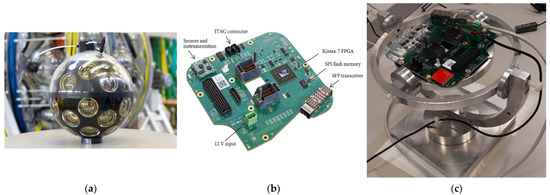
The KM3NeT detectors ORCA (Oscillation Research with Cosmics in the Abyss) and ARCA (Astroparticle Research with Cosmics in the Abyss) are being constructed in two strategic locations at 40–100 km off the coasts of Toulon (France) and Sicily (Italy), at depths between 2.4–3.4 km, respectively, together with the instrumentation network for associated sciences. KM3NeT Detection Units (DUs) are formed by 18 Digital Optical Modules (DOM) each, arranged along vertical slender strings tied by 2 parallel Dyneema® ropes with two copper conductors and 18 fibers as the backbone of the structure, with a breakout of cable at each DOM. Each DOM (Figure 1a) is a high-pressure-resistant borosilicate sphere, housing 31 3 inches photocathode area PMTs, a Central Logic Board (CLB) (Figure 1b), Power Board (voltage supply to CLB), Octopus Boards (to gather signals from PMT bases), and calibration devices such as a NanoBeacon (for timing), a piezo-sensor (for positioning), and other equipment [2].

Figure 1.
The KM3NeT DOM, CLB and CLB onshore calibration test: (a) DOM mounted; (b) CLB unmounted of the DOM; (c) CLB mounted in the “Wobbling” test bench.
Communications, both onshore and offshore, are performed by optical fiber transmission at Gbit/s speed, both from and to the base module via Dense Wavelength Division Multiplexing (DWDM) at the string anchor, where user ports (nodes) for long-term high-bandwidth connection are coupled. The data transmission follows the “all data to shore” scheme where filtering is performed onshore in a high-performance computer farm. The White Rabbit (WR) time synchronization protocol for absolute timestamping from GPS onshore to the connection nodes has been implemented in KM3NeT. Once completed, ORCA and ARCA final layouts (cylindrical structures with diameters of ~212 m and 1000 m, and length of ~200 m and 700 m, respectively) will comprise 1 × 115 and 2 × 115 DUs, with a total instrumented volume of ~7 Mton and ~1 Gton, correspondingly.
3. Digital Compasses: Hardware and Calibration
The CLB has a sensor and instrumentation section (Figure 1b: up-left; Figure 1c: board in red), where the Digital Compass system (AHRS AMS+MEMS system) is incorporated. The AHRS system performs a synchronous work of orientation-tilt measurement of the CLB which is internally fixed into the DOM. Moreover, the AMS sensor estimates the Earth’s magnetic field, providing the field orientation, direction, and intensity of the field. The MEMS estimates the angle/tilt between the compass reference system and the horizontal plane, giving the intensity and direction of the acceleration field. The reference systems of the DOM, CLB, and AHRS board are equivalent by design. Two kinds of Digital Compasses are actually implemented in the CLB: the so-called AHRS-LNS (LIS3LV02DL 3D-accelerometer and HMC5843 3D-magnetometer in separated sensors) [3,4] and LSM303D (3D-accelerometer and 3D-magnetometer integrated in a single custom sensor) [5]. Both have the same goal and closely similar electronic features, but rely on different technology. Both devices share common sources of instrumental uncertainties that propagate to the reconstructed orientation-tilt values. The main sources of uncertainties for Digital Compasses data can be represented by four categories according to the effects on the Accelerometer (A = [Ax,Ay,Az]) and Magnetometer (H = [Hx,Hy,Hz]) vectors: (a) Offsets (shift by a constant vector value with respect to the real one), (b) Scale Factor (instrumental or environmental factors affecting the scale at which each sensor axis is read), (c) Non-Orthogonality (the three axis of the sensor may not be orthogonal due to manufacturing defects), and (d) Misalignment (the axes of the sensor and accelerometer/magnetometer, are not always aligned with the axes of the compass board on which they are mounted). The analytical expressions for corrections of Offsets, Scale Factor, Non-Orthogonality, and Misalignment are conveniently represented in matrix notation. The notation used for description (“Static Calibration”) onshore of orientation-tilt reconstructed data is based on YPR (Yaw/Pitch and Roll) angles [6], and the offshore notation follows the Quaternions (tilt, twist) formalism (“Dynamic Calibration”) [7].
3.1. On-Shore Calibration
Before the CLB integration in the DOM and subsequent DOM integration on the DU and DU operation offshore, two different calibrations (Plane, Wobbling) are carried out onshore for Digital Compasses [8]. Uncertainty < 3 deg in orientation is mandatory before CLB integration in the DOM. For DOM integration in the DU, uncertainty in orientation < 6 deg has to be reached. By establishing such level of uncertainty, it is possible to guarantee the expected performance of the ORCA and ARCA detectors in terms of orientation calibration. In particular, during the Wobbling Calibration, the CLB is attached to a gyroscope-gimbal plastic mounting for free tilting (see Figure 1c). This requires both a surface capable of free rotation and a magnetic field-free environment. The CLB is rotated in eight directions: rotation along its three orthogonal axes, one rotation at 45 deg along the z-axis and their corresponding four mirror rotations. The accelerometer (A) and magnetometer (H) data are recorded during the procedure. A dedicated time-upgrading software uses the collected data to automatically determine an offset vector (Aoff-Hoff) and the necessary rotation matrix (Arot-Hrot) for each accelerometer/magnetometer sensor, and the associated calibration parameters are stored in the database. The implementation process of the offset vector and matrix corrections to raw data is indicated by Equations (1) and (2):
From data obtained by Equations (1) and (2), the YPR values are reconstructed as:
As seen in Equations (3) and (4), PR values are obtained with accelerometer data, but only while Y depends on both accelerometers and magnetometers data. Once the onshore calibration for CLBs is finished, two more tests are performed after the DOM integration: functionality and acceptance. For the offline DOM orientation-tilt calibration procedure, some data quality cuts (filtering) as resolution and communication effects are applied.
3.2. Off-Shore Calibration
For the dimensions of the ORCA and ARCA detectors, the change in time of DOM orientation-tilt values due to seasonally varying sea currents along the DU is a non-negligible issue A “Dynamic Calibration” (time-dependent) instead “Static Calibration” (time-independent) for data has been deemed appropriate for tackling this issue [9]. In the current offshore calibration scheme, two steps are considered: AHRS calibration and Quaternion calibration. The time series of the Quaternion data of each DOM are averaged and the average values interpolated, and so possible outliers are filtered out. Before that, the Digital Compasses are aligned in the following way. Quaternion “Qb” data per DU per 10′ are sorted, a fit to is performed (Q0, Q1, zi, standing for tilt of the DU, twist of the DU, and height of floor i in the DU, respectively), and the calibrated Quaternion Qc is obtained as the average residual Quaternion per DOM. This procedure uses spatial correlations of Digital Compasses in the same DU by fitting a polynomial to Quaternion data. In other words, by starting with Qa as the rotation of the DOM in “static data” structure with respect to the reference DOM, QcQb represents the orientation of the DOM (interpolated at specific time), is the rotation to be applied to the DOM, and Qa = Qc stores the previous rotation in a “static data” structure. For the offline DOM orientation-tilt calibration procedure, some data quality cuts (filtering) are applied to outliers and a missing data policy is introduced.
4. Digital Compasses Performance: Selected Results
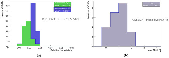
A relative uncertainty for accelerometer and magnetometer (σA/A and σH/H) readout < 10% is demanded as the acceptance criterion for the CLB integration. If the acceptance test is successful, a stringent cut in Yaw residuals (difference with respect to the four cardinal points) is required, one of ≤ 3 deg for CLB integration (Yaw shift ≤ 3 deg in average) and of ≤ 6 deg for DOM integration. After this, calibration constants are allowed to be uploaded to the KM3NeT database. Accelerometer- and magnetometer-derived relative uncertainties, computed for a small CLBs sample during a recent calibration at the UPV KM3NeT Lab, as well as the resulting Yaw shift, are shown in Figure 2.

Figure 2.
Acceptance tests for CLBs in a recent Digital Compasses calibration: (a) accelerometer and magnetometer relative uncertainties; (b) Yaw shift.
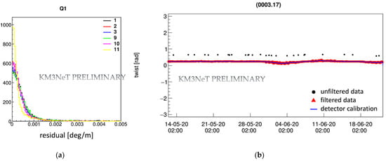
As shown in Figure 2a, relative uncertainties between 1.8–2.5% for accelerometer and magnetometer are obtained, respectively, reasonably well within the acceptance criteria for the CLB integration stage. Moreover, the Yaw shift is ~1 deg, as shown in Figure 2b, so validation of the expected performance of Digital Compasses onshore is reached. Already mentioned above, an orientation-tilt “Dynamic Calibration” is currently being optimized for KM3NeT offshore data. Preliminary results for a calm and a strong sea current period of ~30 days [9] indicate that fitting of polynomial of Quaternions to AHRS data works reasonably, well as illustrated in Figure 3.

Figure 3.
Dynamic orientation calibration for Digital Compasses in ORCA detector: (a) Q1 (twist) residuals (color refers to the DU); (b) Q1 as a function of time (DU3F17).
Very promising results on the resolution obtained for Q1 (twist) for all the DUs in the analyzed period, along with an outstanding time stability, is observed once data filtering conditions (as commented in Section 3.2) are applied and the calibration procedure is carried out. The difference in the residual size (e.g., regarding DU11) is currently a matter of further investigations, arising from the different performance of the two kind of Digital Compasses (AHRS-LNS, LSM303D) installed to the KM3NeT DOMs. Similar results are obtained for Q0 (tilt).
5. Conclusions
The performance of the KM3NeT Digital Compasses shows high reliability from onshore to offshore operation. Onshore, the relative uncertainties of accelerometer and magnetometers are found better than 2.5% (acceptance criteria for CLBs in integration stage is 10%). Offshore evaluations of the outputs of Digital Compasses demonstrate residuals below 1 deg for the twist of the DOMs. Moreover, the horizontal and vertical drag forces along the DU change the orientations of the DOMs, which can be traced in a Dynamic Calibration by means of time-dependent evaluations of the compass output. Preliminary results indicate that fitting of polynomial of Quaternions to AHRS data works reasonably well, with resolutions much better than the required specifications. KM3NeT requires accurate tracing of the DOM positions and orientations in order to reliably reconstruct the physics events of interest and efficiently remove the background contribution. The first data analysis for Digital Compasses demonstrates that the calibration and performance of such devices are sufficiently accurate for reaching the KM3NeT physics goals.
Funding
This research received no external funding.
Institutional Review Board Statement
Not applicable.
Informed Consent Statement
Not applicable.
Data Availability Statement
Not applicable.
Acknowledgments
The author thanks the support of the “María Zambrano” Program of Excellence within the framework of grants for talent retaining of the Spanish Ministry of Universities, funded by the European Union “NextGenerationEU” Program (UPV Contract C16898).
Conflicts of Interest
The author declares no conflict of interest.
References
- Adrián-Martínez, S.; Haren, H. KM3NeT 2.0–Letter of Intent for ARCA and ORCA. J. Phys. G: Nucl. Part. Phys. 2016, 43, 084001. [Google Scholar] [CrossRef]
- Aiello, S.; Albert, A.; Alshamsi, M.; Garre, S.A.; Aly, Z.; Ambrosone, A.; Ameli, F.; Andre, M.; Androulakis, G.; Anghinolfi, M.; et al. The KM3NeT multi-PMT optical module. J. Instrum. 2022, 17, P07038. [Google Scholar] [CrossRef]
- Microelectronics, S.T. LIS3LV02DL MEMS INERTIAL SENSOR; Technical Datasheet: Geneve, Switzerland, 2006. [Google Scholar]
- Honeywell. 3-Axis Digital Compass IC HMC5843; Technical Datasheet: Charlotte, NC, USA, 2009. [Google Scholar]
- Microelectronics, S.T. LSM303DLHC; Technical Datasheet: Geneve, Switzerland, 2013. [Google Scholar]
- Ang, M.H.; Tourassis, V.D. Singularities of Euler and Roll-Pitch-Yaw Representations. IEEE Trans. Aerosp. Electron. Syst. 1987, 23, 317–324. [Google Scholar] [CrossRef]
- Shepperd, S.W. Quaternion from Rotation Matrix. J. Guid. Control 1978, 1, 223–224. [Google Scholar] [CrossRef]
- Androulakis, G.; Bozza, C.; Piatelli, P.; Poma, E.; Riccobene, G.; Viola, S. (National Centre for Scientific Research Demokritos, Athens, Greece). KM3NeT AHRS Calibration. Technical Note KM3NeT_CALIB_2021_001-PRO_AHRS_Calibration_v1. Private communication, 2021.
- de Jong, M. (Nationaal Instituut voor Subatomaire Fysica, Amsterdam, The Netherlands). Orientation Calibration with JPP. Talk at (online) KM3NeT Collaboration Meeting, 8–19 February 2021.
Publisher’s Note: MDPI stays neutral with regard to jurisdictional claims in published maps and institutional affiliations. |
© 2022 by the author. Licensee MDPI, Basel, Switzerland. This article is an open access article distributed under the terms and conditions of the Creative Commons Attribution (CC BY) license (https://creativecommons.org/licenses/by/4.0/).