Proceeding Paper

Studying the Influence of the Impact Gap Value on the Average Translational Speed of the Wheeled Vibration-Driven Robot †

1
Department of Robotics and Integrated Mechanical Engineering Technologies, Lviv Polytechnic National University, 12 S. Bandera Street, 79013 Lviv, Ukraine
2
Faculty of Geoengineering, Mining and Geology, Wroclaw University of Science and Technology, 27 Wybrzeże Wyspiańskiego Street, 50-370 Wroclaw, Poland
*
Author to whom correspondence should be addressed.
Presented at the 1st International Electronic Conference on Machines and Applications, 15–30 September 2022; Available online: https://iecma2022.sciforum.net.
Eng. Proc. 2022, 24(1), 25; https://doi.org/10.3390/IECMA2022-12897
Published: 15 September 2022

Abstract

:
The general design of the wheeled vibration-driven robot is developed in the SolidWorks software (Dassault Systèmes SolidWorks Corporation, Premium 2022, Waltham, MA, USA) on the basis of a double-mass semidefinite oscillatory system. The idea of implementing the vibro-impact working regimes of the internal (disturbing) body is considered. The corresponding mathematical model describing the robot motion conditions is derived using Euler-Lagrange equations. The numerical modeling is carried out by solving the obtained system of differential equations with the help of the Runge-Kutta methods in the Mathematica software (Wolfram Research, Inc., 13.0, Champaign, IL, USA). The computer simulation of the robot motion is conducted in the MapleSim (Waterloo Maple Inc., 2019.1., Waterloo, ON, Canada) and SolidWorks software under different robot design parameters and friction conditions. The experimental prototype of the wheeled vibration-driven robot is developed at the Vibroengineering Laboratory of Lviv Polytechnic National University. The corresponding experimental investigations are carried out in order to verify the correctness of the obtained results of the numerical modeling and computer simulation. All the results are presented in the form of time dependencies of the robot’s basic kinematic characteristics: displacements, velocities, accelerations of the wheeled platform and disturbing body. The influence of the impact gap value on the average translational speed of the robot’s wheeled platform is studied, and the corresponding recommendations for designers and researchers of similar robotic systems are stated. The prospective directions of further investigations on the subject of the present paper and similar vibration-driven locomotion systems are considered.

1. Introduction

Vibration-driven locomotion systems have gained significant interest among scientists and engineers all over the world. These systems can be effectively used for performing different operations in the mediums and environments where the use of other locomotion systems is impossible or inefficient, e.g., for inspecting and cleaning pipelines, delivering drugs or monitoring the inner surfaces of intestines or blood vessels, etc. The problems of modeling the dynamics and kinematics of vibration-driven locomotion systems are currently of significant interest among researchers all over the world. The dynamic behavior of the vibration-driven capsule-type locomotion system with different types of constraints is investigated in [1]. The motion conditions of the vibro-impact system sliding in the small intestine under the controllable sinusoidal excitation are thoroughly studied in [2]. The paper [3] is dedicated to the problems of optimizing the locomotion speed of the vibro-impact capsule-type system with single-sided and double-sided constraints of the internal disturbing mass. In [4], the authors carried out numerical modeling and experimental investigations on the contact conditions between the capsule-type system and the intestine. Similar research on the friction conditions taking place during the capsule-type system sliding inside the intestine is presented in [5].
The problems of optimizing the vibration-driven locomotion systems’ design and control parameters are currently intensively studied. The technique of choosing the optimal design and operational parameters of the capsule-type vibration-driven locomotion system is considered in [6]. The thorough analysis of various friction types’ influence on the kinematic and dynamic parameters of the capsule-type system is carried out in [7]. A comparison of motion characteristics of the pure-vibration and vibro-impact systems under different friction conditions is presented in [8]. The paper [9] is focused on various algorithms allowing for optimizing the control and design parameters of the self-propelled capsule in order to improve the possibilities of its bidirectional motion. In [10], the authors investigated the dynamics of the vibro-impact system sliding along the inclined track under various excitation and friction conditions. The novel optimization method of maximizing the locomotion speed of the self-propelled capsule-type robot moving in an uncertain frictional environment is presented in [11].
One of the common fields of vibro-impact locomotion systems’ implementation is pipeline inspection and cleaning. Thorough reviews of various types of in-pipe robots and the basic prospects of their development are presented in [12,13]. The novel design of the wheeled screw-type robot is proposed in [14]. In [15], the authors improved the wheeled in-pipe robot of the wall-pressing type, and analyzed the robot’s capability of overcoming obstacles. The paper [16] is dedicated to the semi-automatic pipeline inspecting and cleaning system consisting of two movable sections and three driving crank-type mechanisms. In [17], the double-mass vibro-impact in-pipe robot equipped with non-circular driving gear transmission is investigated.
Among the great variety of vibration-driven locomotion systems and vibratory robots, the wheeled ones are the most widespread. The unidirectionally moving wheeled robot driven by the inertial vibration exciter with the rotating unbalanced mass is studied in [18]. The dynamic behavior of the same vibratory robot is numerically modeled in [19]. The present paper is based on the previous investigations of its authors presented in [20,21,22]. The initial idea of developing the wheeled vibro-impact robot has been proposed and theoretically investigated in [20]. The 3D model of the robot and the computer simulation of its motion have been presented in [21]. The basic experimental study of robot kinematic parameters is performed in [22]. The major purpose of the present research consists in experimental substantiating the impact gap value, providing the robot’s maximal locomotion speed. Based on the obtained results, the corresponding recommendations for designers and researchers of similar robotic systems can be drawn.

2. Materials and Methods

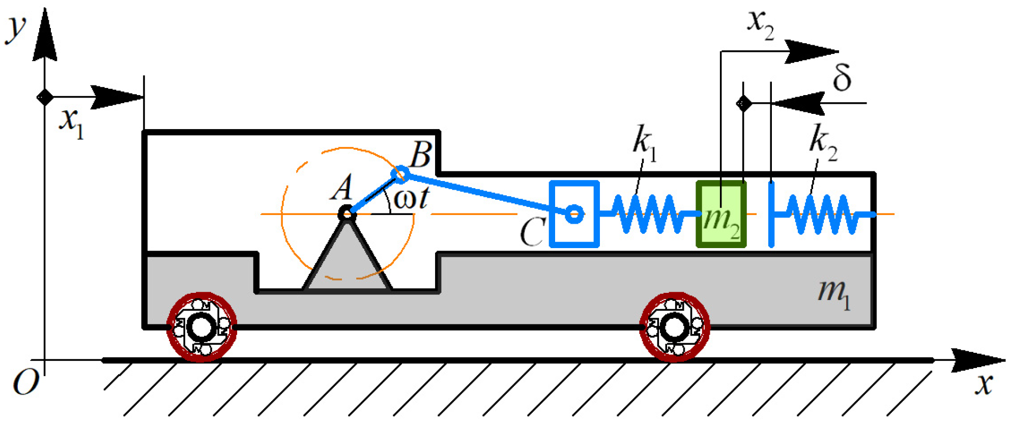
2.1. Simplified Kinematic Diagram and Mathematical Model of the Robot

The double-mass vibro-impact system of the wheeled robot is presented in Figure 1. The crank AB rotates around the hinge A at a constant angular velocity ω. The connecting rod DC is joined with the crank AB and pushes (pulls) the slider C. The latter is connected with the stiffness spring k 1 , actuating the impact body of the mass m 2 . The maximal relative displacement of the impact body is restricted by the impact plate and stiffness spring k 2 . The robot’s body of mass m 1 is assembled on the wheeled chassis. Using the overrunning (free-wheel) clutches, the unidirectional rotation of the wheels is provided. In order to study the robot locomotion, the inertial coordinate system xOy and the corresponding generalized coordinate x 1 are applied. The relative motion of the impact mass along the robot’s body is described by the coordinate x 2 .
Using Euler–Lagrange equations, the simplified mathematical model describing the robot locomotion can be written as follows:
( m 1 + m 2 ) x ¨ 1 + ( x C x 2 ) k 1 + ( δ 0 x 2 ) k 2 * = F b r ,
m 2 x ¨ 2 + ( x 2 x C ) k 1 + ( x 2 δ 0 ) k 2 * = 0 ,
where
x C = l A B cos ( ω t ) + l B C 2 ( l A B sin ( ω t ) ) 2 l A B l B C l B C l A B l A B ( cos ( ω t ) 1 ) ,
k 2 * = { k 2 , x 2 δ 0 , 0 , x 2 < δ 0 ,
F b r = { 0 , sign ( x ˙ 1 ) 0 , ( x C x 2 ) k 1 + ( δ 0 x 2 ) k 2 * , sign ( x ˙ 1 ) < 0 ,
l A B , l B C are the lengths of the rods AB, BC, respectively; δ 0 is the initial impact gap (the smallest distance between the impact mass m 2 and the impact plate when the crank is in a state of rest and takes a horizontal position).
The numerical modeling is carried out by solving the derived system of differential equations with the help of the Runge-Kutta methods in the Mathematica software.

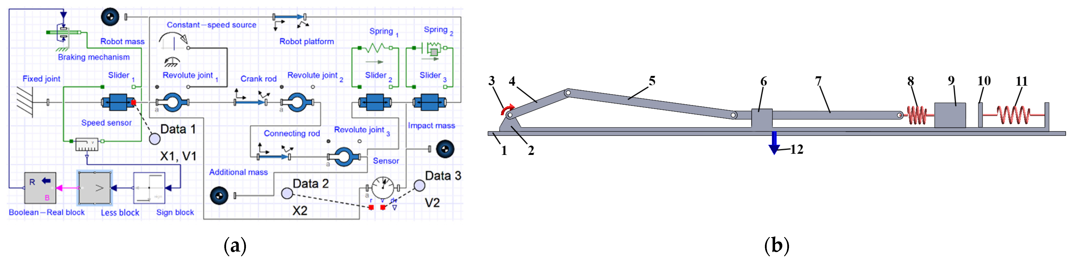
2.2. Simulation Models of the Robot’s Oscillatory System

Along with the theoretical studies, the computer simulation of the robot’s motion has been carried out. Figure 2 shows two simulation models of the robot’s oscillatory system developed in the MapleSim and SolidWorks software [21]. The models correspond to the robot’s kinematic diagram considered above. The robot’s body (2) is sliding along a horizontal surface (1). The rotary motor (3) actuates the crank (4) connected with the rod (5). The latter sets the sliding rod (7) into the rectilinear oscillatory motion along the guide (6). Due to the fact that the impact body (9) is connected with the sliding rod (7) by the spring (8), the oscillations of the body (9) are excited. The relative motion of the impact mass (9) is restricted by the impact plate (10) connected with the robot’s body by the spring (11). In order to block the backward (leftward) motion of the robot’s body, the special braking system (12) is used, providing different values of friction forces for different motion directions.

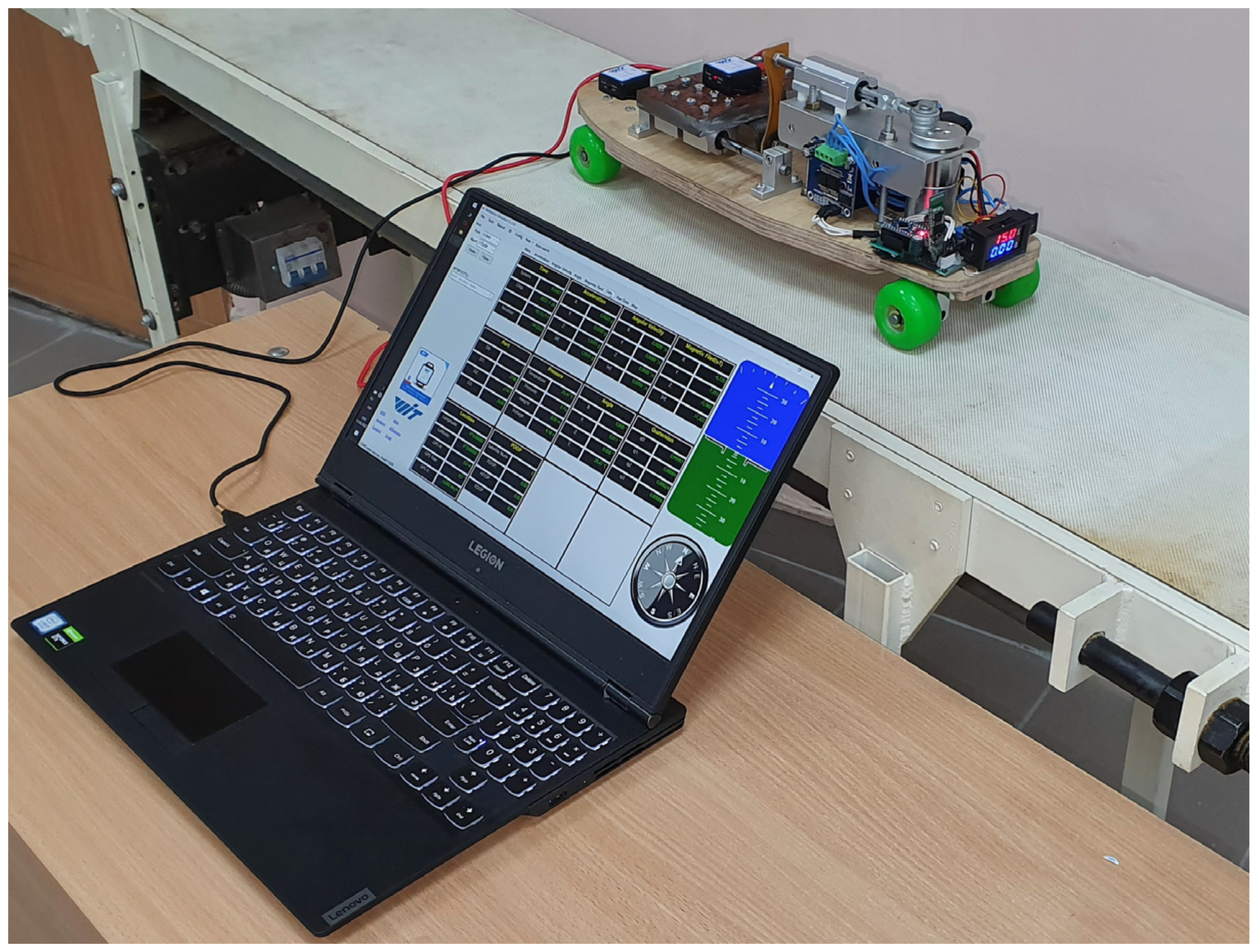
2.3. Experimental Prototype of the Wheeled Vibration-Driven Robot

To verify the results of the numerical modeling and computer simulation, the robot’s experimental prototype has been designed and implemented in practice [22]. The movable platform (1) is mounted on the wheeled chassis (2) (Figure 3). The overrunning (free-wheel) clutches (3) restrict the wheels’ backward rotation. The eccentric disc (crank) (4) is fixed on the motor’s shaft (5). The control system (6) is based on Arduino hardware and software. The rod (7) actuated by the eccentric (4) sets the sliding rod (8) into the oscillatory motion along the guide (9). The rod (8) is fixed to the upper end of the flat spring (10). Its lower end is connected with the impact body (11) sliding along the guides (12) with the help of the linear bearings (13). The motion of the impact body (11) is restricted by the rubber damper (14) fixed on the robot’s platform. The motor (5) and the control system (6) are powered by the batteries placed in the boxes (17). The voltmeter-amperemeter (18) is used for registering the total power supply during the robot’s motion under different operational conditions.

3. Results and Discussion

The study on the influence of the impact gap value on the average translational speed of the wheeled vibration-driven robot is carried out under the following conditions. The robot moves along a horizontal rubber track; the power supply is constant; the inertial, stiffness and damping parameters of the robot’s oscillatory system remain unchangeable [22]. The only parameter being changed is the initial impact gap δ 0 , which can take the following values: 35 mm (nonimpact mode), 4 mm, and 0 mm (impact modes) (see Figure 4).

3.1. Results of Numerical Modeling and Computer Simulation

The numerical modeling has been carried out in the Mathematica software, while the computer simulation has been performed in the MapleSim and SolidWorks Motion software. Due to the fact that the obtained results are very similar, let us present only the plots obtained in the Mathematica software (see Figure 5) under the following input parameters: m 1 = 3.7   kg , m 2 = 0.6   kg , ω = 37.7   rad / s (6 Hz), l A B = 0.025   m , l B C = 0.08   m , k 1 = 800   N / m , k 2 = 10 4   N / m . During the time interval of 20 s (0–20 s), the robot’s body passed the distance of 6.8 m at the initial impact gap of 4 mm; the distance of about 6.5 m—at the gaps of 2 and 6 mm; the distance of 5.9 m—at the gap of 8 mm. The smallest distance of 5.6 m has been passed under the zero-gap conditions. Therefore, the largest locomotion speed is about 0.34 m/s at an impact gap of 4 mm.

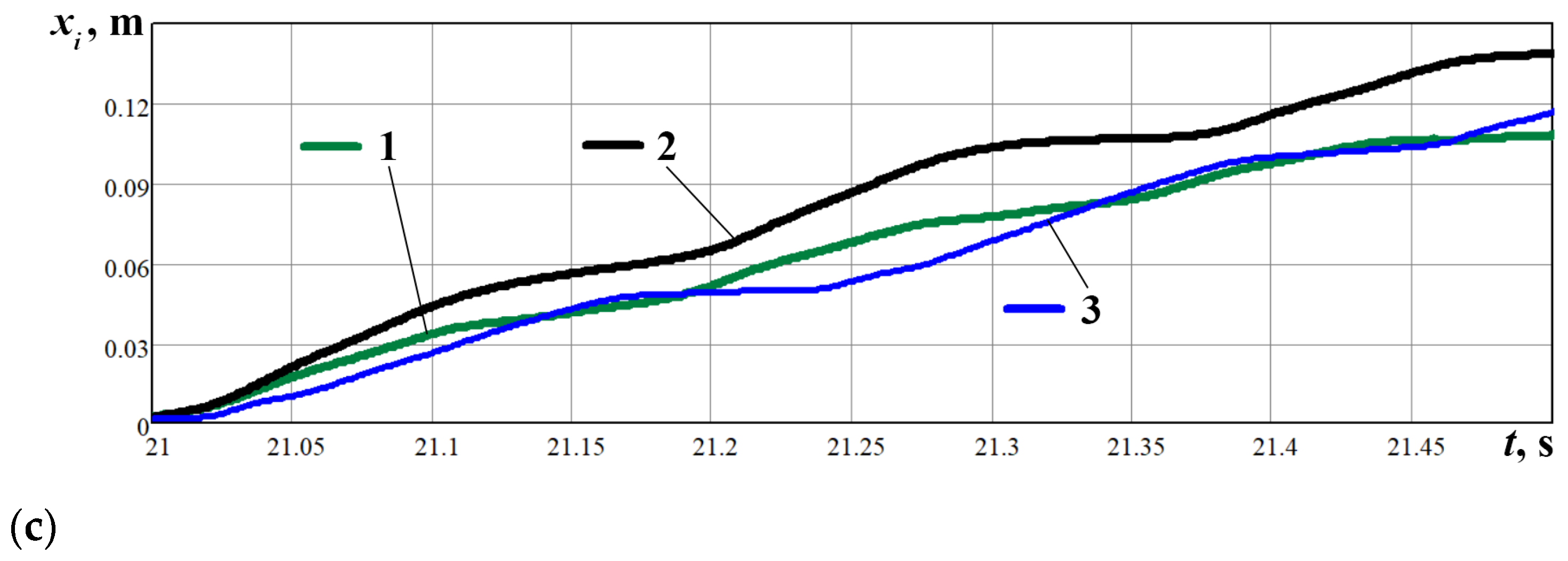
3.2. Experimental Results

The experimental investigations (Figure 6) have been carried out at the Vibroengineering Laboratory of Lviv Polytechnic National University under three impact gap values: 35 mm (nonimpact mode), 4 mm, and 0 mm (impact modes). The control system allows for providing a constant power supply to the robot’s drive. In such a case, the forced frequencies took the following values: 6.9 Hz (nonimpact mode), 6.3 Hz (impact gap of 4 mm), and 5.4 Hz (zero-gap conditions). The wheeled platform and impact body accelerations have been registered by the WitMotion BWT901CL accelerometers (WitMotion Shenzhen Co., Ltd., BWT901CL, Shenzhen, China). The experimental data have been processed with the help of the WitMotion and MathCad software (PTC Inc., Mathcad 15.0, Needham, MA, USA).
The results of the experimental investigations are presented in Figure 7a. The experimental data (curves 4, 5, 6) of the robot accelerations have been interpolated (curves 1, 2, 3) and numerically integrated with the help of the MathCad software. The corresponding time dependencies of the robot’s instantaneous speeds and displacements have been obtained (see Figure 7b,c). Numerical integration of the obtained results allows for concluding that the robot’s average locomotion speed reaches 0.34 m/s at the impact gap of 4 mm, whilst the use of the non-impact and zero-gap operational conditions provides almost equal average velocities of about 0.26 m/s. Some differences between the modeling results and experimental data can be explained by the fact that the forced frequency changes from 6.9 Hz under the non-impact conditions to 5.4 Hz at zero-gap mode despite the unchangeable power supply to the robot’s drive.

4. Conclusions

The present paper is dedicated to studying the dynamic behavior of the wheeled vibration-driven robot. The robot’s general design idea is proposed in the form of the 3D model developed in the SolidWorks software and implemented in practice at the Vibroengineering Laboratory of Lviv Polytechnic National University. The mathematical model describing the robot locomotion is deduced using Euler–Lagrange equations. The simplified computer simulation models of the robot’s oscillatory system are developed in the MapleSim and SolidWorks software. The robot motion is numerically modeled, simulated and experimentally tested under different impact gap values. The obtained results satisfactorily agree with one another. Considering the forced frequency of about 5.4–6.9 Hz, the optimal impact gap value is in the range of 3–5 mm. In such a case, the robot’s average locomotion velocity reaches 0.34 m/s. Herewith, the use of the non-impact and zero-gap operational conditions provides almost equal average velocities of about 0.26 m/s. The obtained results can be used by designers and researchers of similar robotic systems while choosing the optimal control strategies and defining the rational design parameters. The scope of further investigations on the subject of the paper can be focused on analyzing the robot’s drive power consumption under different operational conditions and studying the complex optimization parameter, maximizing the robot’s average locomotion speed and minimizing the drive power consumption.

Author Contributions

Conceptualization, V.K. and V.G.; methodology, V.K.; software, O.K.; validation, V.K., O.K. and V.G.; formal analysis, P.K.; investigation, V.K.; resources, V.K.; writing—original draft preparation, V.K.; writing—review and editing, V.K.; visualization, O.K.; supervision, V.G. and P.K. All authors have read and agreed to the published version of the manuscript.

Funding

Pavlo Krot has received funding from the European Institute of Innovation and Technology (EIT), a body of the European Union, under the Horizon 2020, the EU Framework Programme for Research and Innovation. This work is supported by EIT RawMaterials GmbH under Framework Partnership Agreement No. 19018 (AMICOS. Autonomous Monitoring and Control System for Mining Plants).

Institutional Review Board Statement

Not applicable.

Informed Consent Statement

Not applicable.

Data Availability Statement

Data supporting reported results can be obtained from the authors.

Conflicts of Interest

The authors declare no conflict of interest. The funders had no role in the design of the study; in the collection, analyses, or interpretation of data; in the writing of the manuscript, or in the decision to publish the results.

References

  1. Yan, Y.; Liu, Y.; Liao, M. A Comparative Study of the Vibro-Impact Capsule Systems with One-Sided and Two-Sided Constraints. Nonlinear Dyn. 2017, 89, 1063–1087. [Google Scholar] [CrossRef] [PubMed]
  2. Yan, Y.; Liu, Y.; Manfredi, L.; Prasad, S. Modelling of a Vibro-Impact Self-Propelled Capsule in the Small Intestine. Nonlinear Dyn. 2019, 96, 123–144. [Google Scholar] [CrossRef]
  3. Maolin, L.; Yao, Y.; Yang, L. Optimization of the Vibro-Impact Capsule System for Promoting Progression Speed. MATEC Web Conf. 2018, 148, 10002. [Google Scholar] [CrossRef]
  4. Guo, B.; Liu, Y.; Prasad, S. Modelling of Capsule–Intestine Contact for a Self-Propelled Capsule Robot via Experimental and Numerical Investigation. Nonlinear Dyn. 2019, 98, 3155–3167. [Google Scholar] [CrossRef]
  5. Guo, B.; Ley, E.; Tian, J.; Zhang, J.; Liu, Y.; Prasad, S. Experimental and Numerical Studies of Intestinal Frictions for Propulsive Force Optimisation of a Vibro-Impact Capsule System. Nonlinear Dyn. 2020, 101, 65–83. [Google Scholar] [CrossRef]
  6. Nguyen, K.T.; Nguyen, V.D.; Ho, K.T.; La, N.T. Modelling of a Vibration-Driven Module for Capsule Locomotion Systems. Int. J. Mech. Prod. Eng. Res. Dev. 2020, 10, 837–850. [Google Scholar] [CrossRef]
  7. Nguyen, K.-T.; La, N.-T.; Ho, K.-T.; Ngo, Q.-H.; Chu, N.-H.; Nguyen, V.-D. The Effect of Friction on the Vibro-Impact Locomotion System: Modeling and Dynamic Response. Meccanica 2021, 56, 2121–2137. [Google Scholar] [CrossRef]
  8. La, N.-T.; Nguyen, T.-T.; Nguyen, V.-D. A Comparative Study on the Two Vibration Driven Locomotion Systems in Various Friction Levels. Vietnam J. Mech. 2021, 43, 121–137. [Google Scholar] [CrossRef]
  9. Zhu, J.; Liao, M.; Zheng, Y.; Qi, S.; Li, Z.; Zeng, Z. Multi-Objective Optimisation Based on Reliability Analysis of a Self-Propelled Capsule System. Available online: https://doi.org/10.1007/s11012-022-01519-3 (accessed on 14 September 2022).
  10. Duong, T.-H.; Van, C.N.; Ho, K.-T.; La, N.-T.; Ngo, Q.-H.; Nguyen, K.-T.; Hoang, T.-D.; Chu, N.-H.; Nguyen, V.-D. Dynamic Response of Vibro-Impact Capsule Moving on the Inclined Track and Stochastic Slope. Available online: https://doi.org/10.1007/s11012-022-01521-9 (accessed on 14 September 2022).
  11. Liao, M.; Zhang, J.; Liu, Y.; Zhu, D. Speed Optimisation and Reliability Analysis of a Self-Propelled Capsule Robot Moving in an Uncertain Frictional Environment. Int. J. Mech. Sci. 2022, 221, 107156. [Google Scholar] [CrossRef]
  12. Verma, A.; Kaiwart, A.; Dubey, N.D.; Naseer, F.; Pradhan, S. A Review on Various Types of In-Pipe Inspection Robot. Mater. Today Proc. 2021, 50, 1425–1434. [Google Scholar] [CrossRef]
  13. Jang, H.; Kim, T.Y.; Lee, Y.C.; Kim, Y.S.; Kim, J.; Lee, H.Y.; Choi, H.R. A Review: Technological Trends and Development Direction of Pipeline Robot Systems. J. Intell. Robot. Syst. 2022, 105, 59. [Google Scholar] [CrossRef]
  14. Nayak, A.; Pradhan, S.K. Design of a New In-Pipe Inspection Robot. Procedia Eng. 2014, 97, 2081–2091. [Google Scholar] [CrossRef]
  15. Feng, G.; Li, W.; Li, Z.; He, Z. Development of a Wheeled and Wall-Pressing Type in-Pipe Robot for Water Pipelines Cleaning and Its Traveling Capability. Mechanika 2020, 26, 134–145. [Google Scholar] [CrossRef]
  16. Salvatore, M.M.; Galloro, A.; Muzzi, L.; Pullano, G.; Odry, P.; Carbone, G. Design of PEIS: A Low-Cost Pipe Inspector Robot. Robotics 2021, 10, 74. [Google Scholar] [CrossRef]
  17. Liu, D.; Lu, J.; Cao, Y.; Jin, X. Dynamic Characteristics of Two-Mass Impact Pipeline Robot Driven by Non-Circular Gears. Adv. Mech. Eng. 2022, 14, 1–13. [Google Scholar] [CrossRef]
  18. Loukanov, I.A.; Vitliemov, V.G.; Ivanov, I.V. Dynamics of a Vibration-Driven One-Way Moving Wheeled Robot. IOSR J. Mech. Civ. Eng. 2016, 13, 14–22. [Google Scholar] [CrossRef]
  19. Loukanov, I.A.; Vitliemov, V.G.; Ivanov, I.V. Dynamics of a Mobile Mechanical System with Vibration Propulsion (VibroBot). Int. J. Res. Eng. Sci. 2016, 4, 44–51. [Google Scholar]
  20. Korendiy, V.; Gursky, V.; Kachur, O.; Dmyterko, P.; Kotsiumbas, O.; Havrylchenko, O. Mathematical Model and Motion Analysis of a Wheeled Vibro-Impact Locomotion System. Vibroeng. Procedia 2022, 41, 77–83. [Google Scholar] [CrossRef]
  21. Korendiy, V.; Kachur, O.; Gursky, V.; Kotsiumbas, O.; Dmyterko, P.; Nikipchuk, S.; Danylo, Y. Motion Simulation and Impact Gap Verification of a Wheeled Vibration-Driven Robot for Pipelines Inspection. Vibroeng. Procedia 2022, 41, 22521. [Google Scholar] [CrossRef]
  22. Korendiy, V.; Kachur, O.; Gursky, V.; Gurey, V.; Pelio, R.; Kotsiumbas, O. Experimental Investigation of Kinematic Characteristics of a Wheeled Vibration-Driven Robot. Vibroeng. Procedia 2022, 43, 14–20. [Google Scholar] [CrossRef]
Figure 1. Simplified kinematic diagram of the wheeled vibro-impact robot.
Engproc 24 00025 g001
Figure 2. Simulation models of the robot’s oscillatory system: (a) MapleSim model; (b) SolidWorks model. (1: stationary horizontal surface; 2: robot’s body; 3: rotary motor; 4: crank; 5: connecting rod; 6: guide; 7: sliding rod; 8: spring; 9: disturbing body; 10: impact plate; 11: impact spring; 12: controllable braking force).
Engproc 24 00025 g002
Figure 3. Experimental prototype of the wheeled vibration-driven robot: (a) 3D design; (b) Implemented robot. (1: movable platform; 2: wheeled chassis; 3: overrunning (free-wheel) clutches; 4: eccentric; 5: electric motor; 6: control system; 7: connecting rod; 8: sliding rod; 9: guide; 10: flat spring; 11: impact body; 12: guide rods; 13: linear bearings; 14: rubber damper; 15, 16: accelerometers; 17: boxes with batteries; 18: voltmeter-amperemeter).
Engproc 24 00025 g003
Figure 4. Three initial impact gap values being experimentally studied.
Engproc 24 00025 g004
Figure 5. The numerical modeling results of the robot locomotion at different impact gap values. (blue line: 0 mm; brown line: 2 mm; green line: 4 mm; pink line: 6 mm; red line: 8 mm; The dots show the robot’s average speed at different impact gaps: 0 m, 0.002 m, 0.004 m, 0.006 m, 0.008 m.)
Engproc 24 00025 g005
Figure 6. Experimental equipment used for studying the robot’s locomotion conditions.
Engproc 24 00025 g006
Figure 7. Experimental results of robot motion: (a) Accelerations; (b) Velocities; (c) Displacements. (Lines 1, 2, 3: the interpolated data at different impact gap values: 35 mm, 4 mm, and 0 mm, respectively; Lines 4, 5, 6: the experimental data registered by the accelerometer at different impact gap values: 35 mm, 4 mm, and 0 mm, respectively.)
Engproc 24 00025 g007aEngproc 24 00025 g007b
Publisher’s Note: MDPI stays neutral with regard to jurisdictional claims in published maps and institutional affiliations.

