Proceeding Paper

Experimental Study on Bond Strength of Locally Manufactured GFRP Bar †

by
Muhammad Saad Ifrahim
*,
Abdul Jabbar Sangi
and
Syed Muhammad Hamza
Department of Civil Engineering, NED University of Engineering and Technology, Karachi 75270, Pakistan
*
Author to whom correspondence should be addressed.
Presented at the 12th International Civil Engineering Conference (ICEC-2022), Karachi, Pakistan, 13–14 May 2022.
Eng. Proc. 2022, 22(1), 4; https://doi.org/10.3390/engproc2022022004
Published: 22 September 2022
(This article belongs to the Proceedings of The 12th International Civil Engineering Conference)

Abstract

:
GFRP rebar is found corrosion resistant and has a greater tensile strength. GFRP rebars are being explored as an alternative way to preventing the degradation of civil infrastructures. GFRP materials, as opposed to steel reinforcement, have anisotropic, non-homogeneous, linearly elastic properties and having different surface deformation patterns (e.g., ribs, thread wrapped, sand coated etc.), which may lead to a unique force transfer mechanism between the reinforcement and the concrete. In order to investigate the bond strength of steel and GFRP bars, total twelve (12) cube specimens (200 mm × 200 mm × 200 mm) were cast. The effect of bar material, diameter, and embedded length was examined on bond strength. The bond strength of GFRP bar to concrete was shown to be 42 percent less than the bond strength of steel rebar to concrete. It was also found that the bond strength of GFRP bar to concrete reduced as bar diameter and embedded length increased.

1. Introduction

The lifespan of reinforced concrete (RC) infrastructure is greatly reduced by corrosion of the steel bars reinforcing material. Corroded internal steel reinforcement loses its strength that makes the RC structure susceptible to failure. For infrastructure in coastal areas, such as Karachi, Pakistan, the rate of corrosion is considerably higher. The use of alternative reinforcement is a possible solution to this problem. Glass Fibre reinforced polymer bars are found to be a potential replacement of steel rebar. GFRP bars have several advantages over traditional steel bars, including lower density, higher tensile strength, and no corrosion, even in harsh environments [1].
The bond properties of GFRP bars in concrete are the most important factor in the material’s use to concrete structures. GFRP materials, unlike steel reinforcement, have anisotropic, non-homogeneous, linear elastic characteristics, and having different surface deformation patterns (e.g., ribbed, sand coated, thread wrapped etc.) resulting in a distinct force transmission mechanism between the reinforcement and the concrete [2,3,4,5].
Researchers [5,6,7,8] conducted a wide range of experiments and used the results to predict several models/bond strength equations. However, the ideal equation for calculating bond strength analytically has yet to be established. In addition, according to Emparanza et al. [9], the producer of GFRP bars around the globe produce proprietary products resulting in wide ranging properties; therefore, it is imperative to characterize locally manufactured GFRP bars.
In this study, the bond behaviour of locally manufactured GFRP bar to concrete is experimentally studied using direct pull-out test. The scope of this study is limited to examine the effect of rebar material, diameter and embedded length on bond strength.

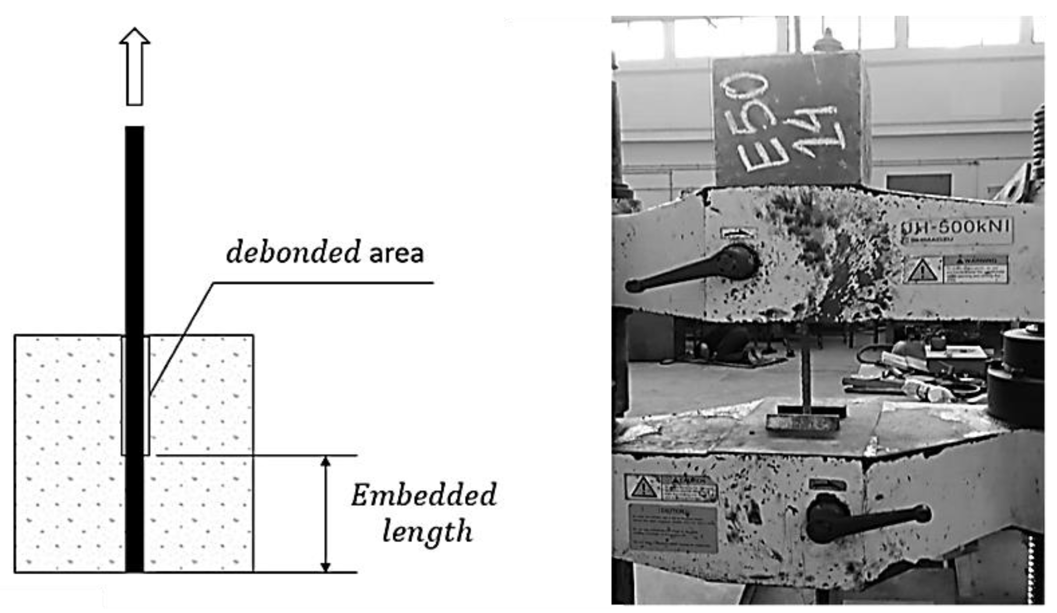
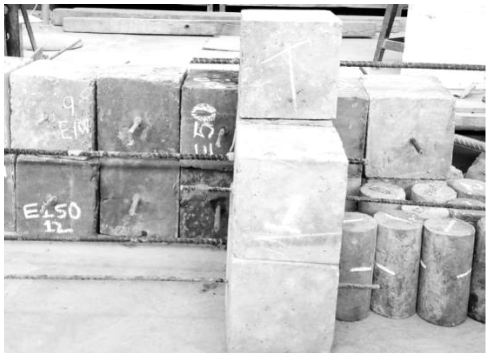
2. Experimental Programme

In order to investigate the bond strength of steel and GFRP bars, total twelve (12) cube specimens (200 mm × 200 mm × 200 mm) were cast. Bond strength was investigated in relation to bar material, diameter, and embedded length. Two specimens were cast using steel bars while rest using GFRP bars. Three (03) different bar sizes (10 mm, 12 mm, and 16 mm) and three (03) different embedded lengths (50 mm, 100 mm, and 150 mm) were considered. Figure 1 depicts the pull-out test apparatus, whereas Figure 2 depicts the cast specimens.

2.1. Materials

The desired concrete compressive strength was 21 MPa. Concrete mix design agreed with ACI-211 specifications. The design of the concrete mix is shown in Table 1. At 28 days of curing, the average compressive strength of concrete was found to be 23 MPa. The yield strength of steel rebar was 420 MPa while the ultimate tensile strength of GFRP bar was 848 MPa. The surface deformation pattern of locally manufactured GFRP bar is thread wrapped as presented in Figure 3.

2.2. Test Results

The test results for various types of specimens are shown in Table 2. The maximum force of pull-out, bond-stress (determined by dividing the maximum pull-out force by the surface area of the bar in contact with the concrete), average bond strength, maximum slippage, and average max slippage are all included in this table. Because there are two replicates for each specimen, the average bond strength and average maximum slippage were estimated by taking the mean. The failure mode was found to be pull out in all specimens. The pull-out specimen identification is defined in Figure 4.

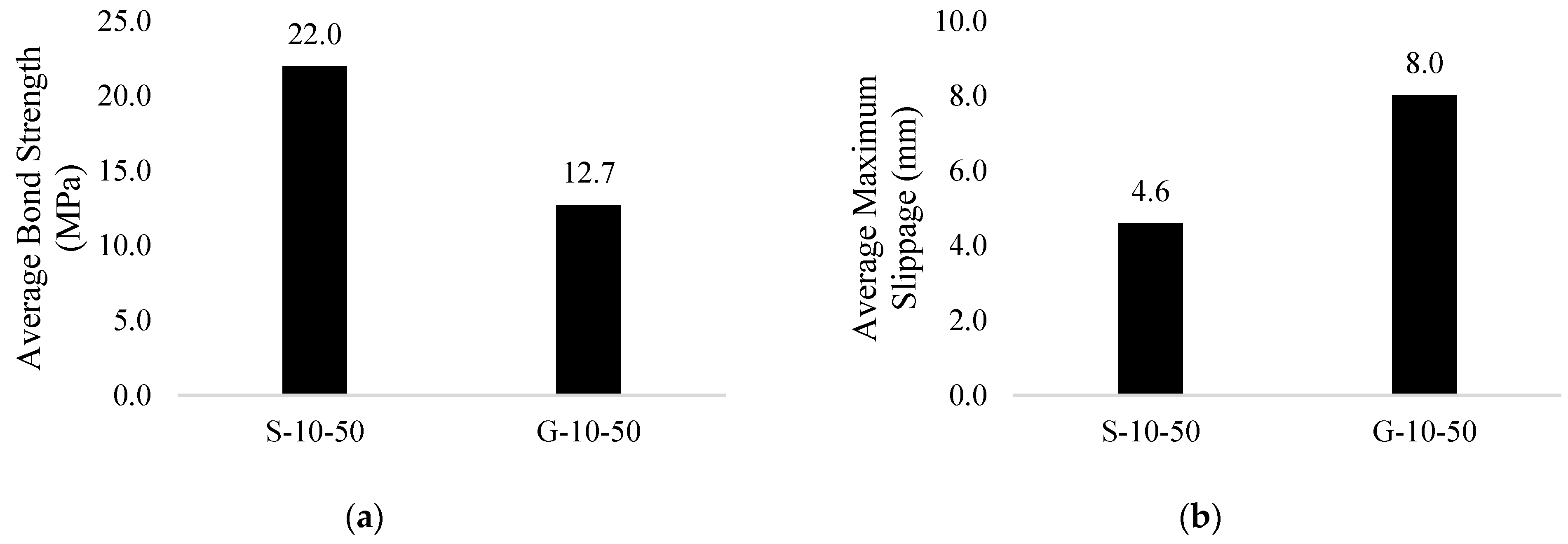
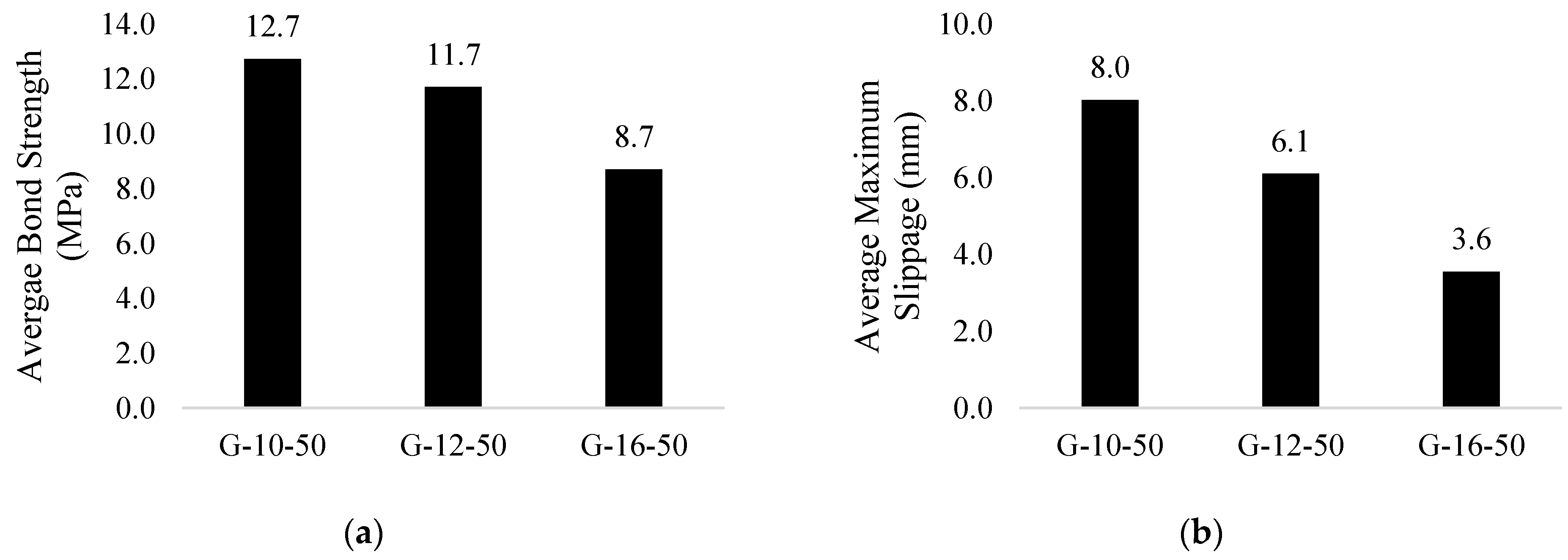
3. Results and Discussion
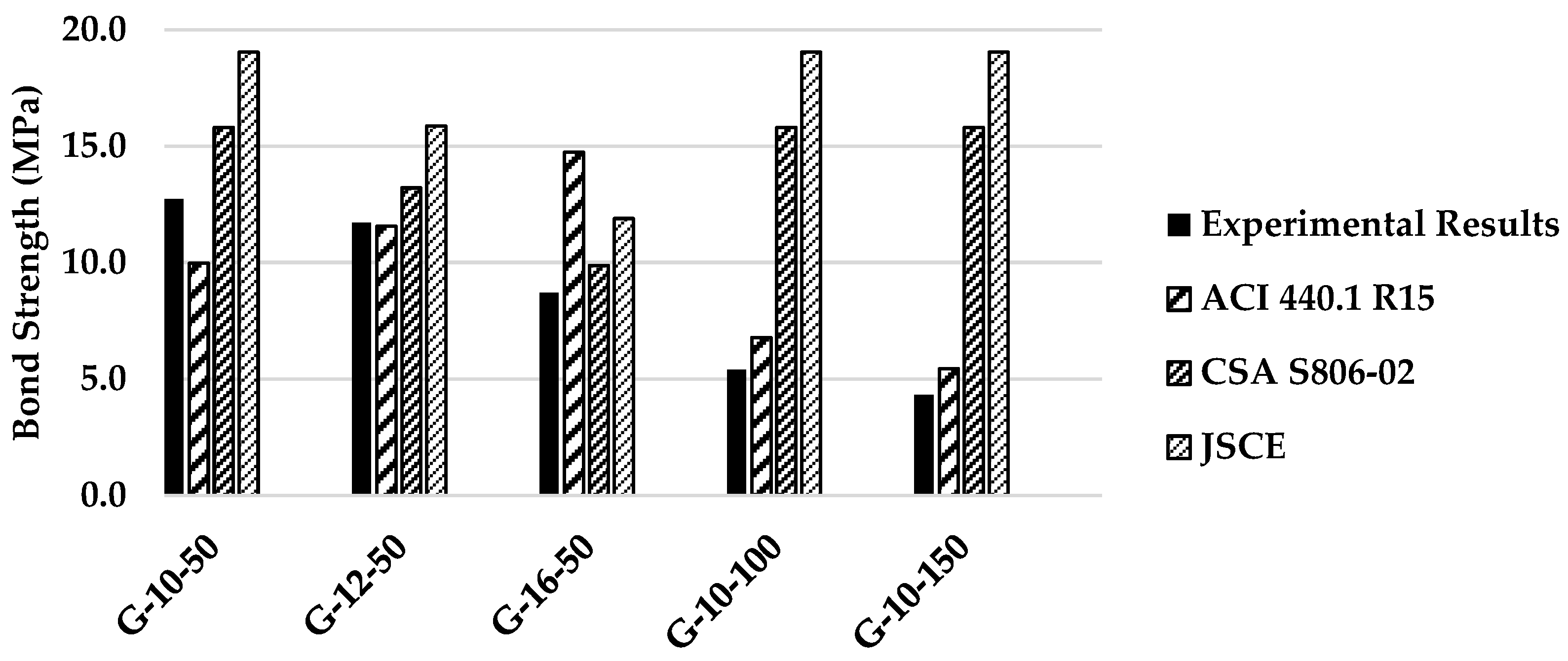
The bond strength of steel and GFRP bar was compared in this study, and the influence of bar diameter and embedding length on GFRP bar bond strength was investigated. Figure 5 compares the bond strength and maximum slippage of steel and GFRP bars. GFRP bar’s bond strength is found to be 42% less than steel rebar, while slippage is 74% higher. This is attributed to the reason that the deformed surface of steel rebar provides stronger mechanical interlocking than the thread wrapped surface of GFRP bar.
The influence of bar diameter on GFRP bar bond strength and slippage is shown in Figure 6. It is found that as the diameter of the bar increases, the bond strength and slippage decreases. This is due to an increase in the contact area between the bar and the concrete as the diameter increases. During the casting of concrete, the natural entrapment of voids and other imperfections at the contact increases the likelihood of a poor bond between the concrete and the bar. Furthermore, as the contact area increases, the frictional force increases, reducing slippage. When the bar diameter is increased from 10 mm to 12 mm, the average bond strength reduces by 8% while maximum slippage reduces by 23.9%, and when the bar diameter is increased from 12 mm to 16 mm, the average bond strength decreases by 25.6% while slippage decreases by 41.8%.
The influence of embedded length on GFRP bar’s bond strength and slippage is shown in Figure 7. This is because with increase in embedded length there is increase in contact area and the stress distribution becomes uneven; therefore, there is decrease in bond strength. Furthermore, with increase in embedded length there is relative increase in pull out force and longer strain length available for deformation; therefore, slippage decreases. When the embedded length is increased from 50 mm to 100 mm, the average bond strength reduces by 57.5% while maximum slippage increases by 6.1%, and when the embedded length is increased from 100 mm to 150 mm, the average bond strength decreases by 20% while slippage increases by 24%.

Analytical Results

The bond strength can be estimated analytically using equations proposed by different codes, such as ACI 440.1 R15 [10], CSA S806-02 [11], and JSCE [12]. The equations used for computing bond strength analytically are given in Table 3. Experimental and analytical results are tabulated in Table 4. Figure 8 shows comparison between experimental and analytical results. The results are found to be in good accord with the predictions of ACI 440.1 R15. The overall disparity between experimental and analytical results are found to be 7.7%, 36% and 47% as per ACI 440.1 R15 [10], CSA S806-02 [11], and JSCE [12], respectively.
It should be noted that CSA S806-02 [11] and JSCE [12] do not consider the effect of embedded length into account, therefore, bond strength comes out constant at varied development lengths, resulting in apparent discrepancy between experimental and anticipated values.

4. Conclusions

Based on the findings, the following conclusions have been drawn:
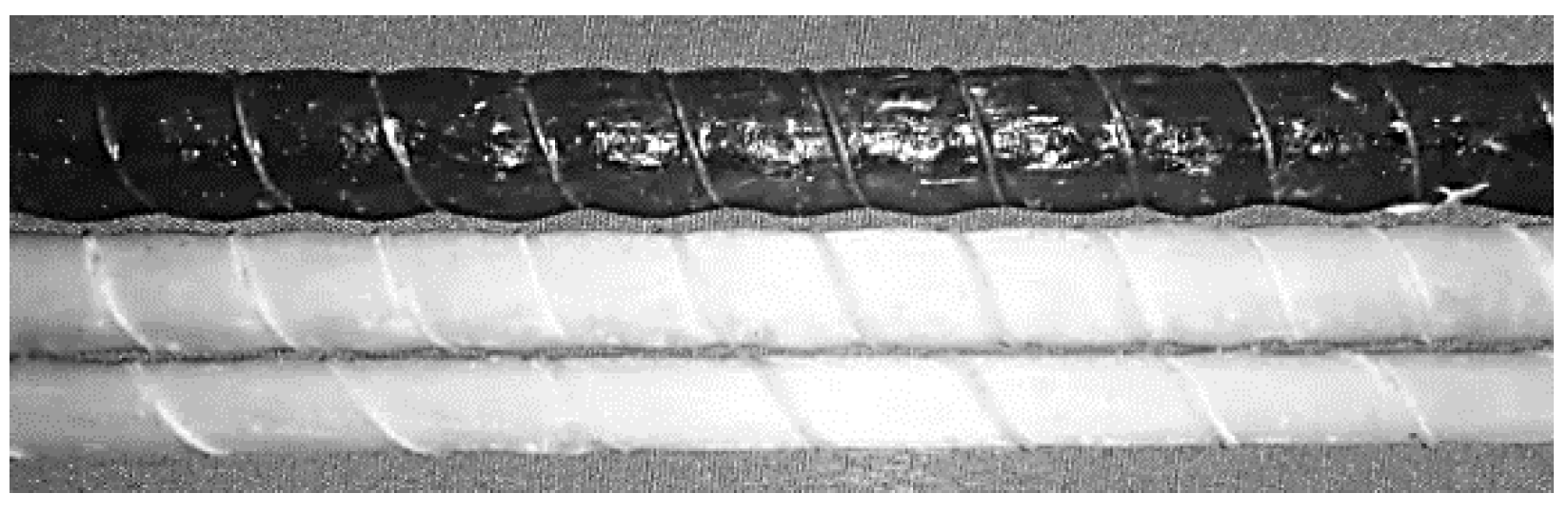
  • It is found there is pull-out failure in all the tested specimens.
  • The bond strength of the locally manufactured GFRP bar is found 42% less than steel rebar, therefore, it is suggested to improve the mechanical interlock of GFRP bar.
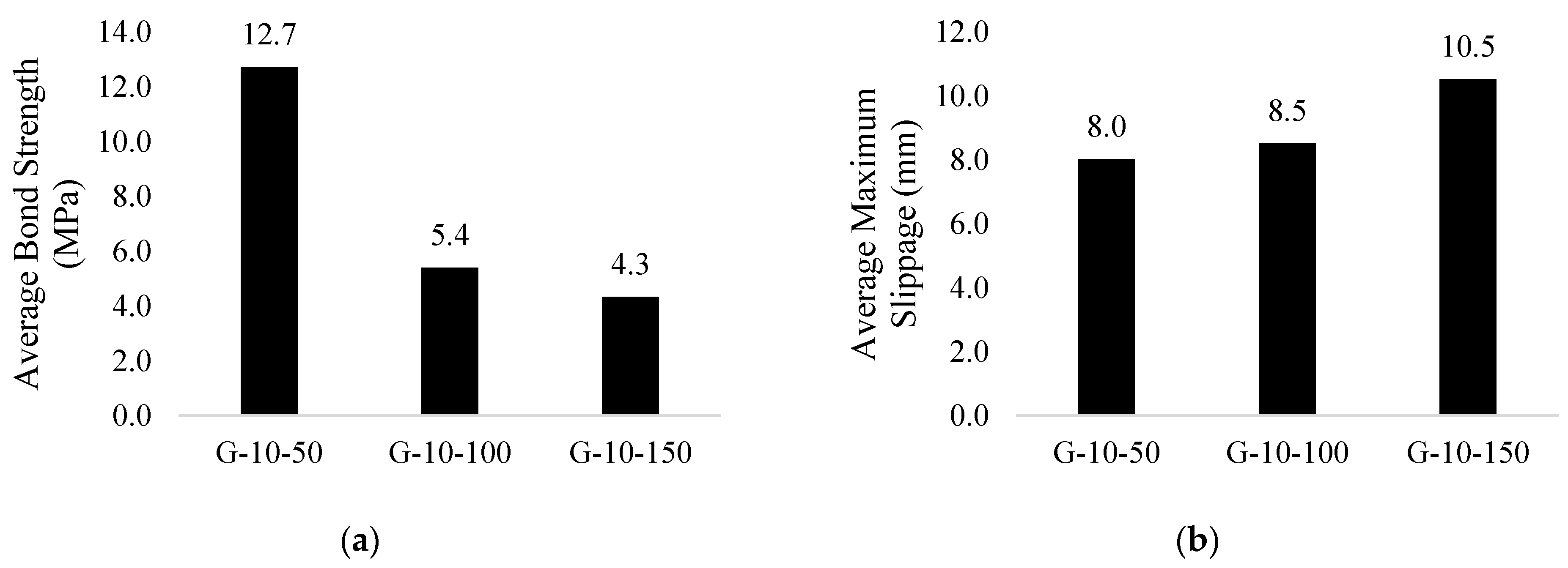
  • The bond strength and maximum slippage of GFRP bar is found to be decreased with increase in diameter.
  • The bond strength decreased while maximum slippage increased with increase in embedded length of GFRP bar.
  • The experimental results are found to be in good accord with ACI 440.1 R15 predictions.

Author Contributions

Visualization, Methodology, Formal analysis, validation, writing—original draft preparation, M.S.I.; Conceptualization, writing—review and editing, Resources, Project administration and supervision: A.J.S.; Investigation, S.M.H. All authors have read and agreed to the published version of the manuscript.

Funding

This research received no external funding.

Institutional Review Board Statement

Not applicable.

Informed Consent Statement

Not applicable.

Data Availability Statement

Not Applicable.

Acknowledgments

The Authors are grateful to Civil Engineering department, NED University of Engineering and Technology, Karachi, Pakistan for assistance and support. The first author is thankful for T-Rod international, Karachi on providing GFRP rebar for the research.

Conflicts of Interest

The authors declare no conflict of interest.

References

  1. Nanni, A.; de Luca, A.; Zadeh, H.J. Reinforced Concrete with FRP Bars Mechanics and Design; CRC Press: Boca Raton, FL, USA, 2014. [Google Scholar]
  2. Brown, V.L.; Bartholomew, C.L. FRP reinforcing bars in reinforced concrete members. Mater. J. 1993, 90, 34–39. [Google Scholar]
  3. Pecce, M.; Manfredi, G.; Realfonzo, R.; Cosenza, E. Experimental and analytical evaluation of bond properties of GFRP bars. J. Mater. Civ. Eng. 2001, 13, 282–290. [Google Scholar] [CrossRef]
  4. Achillides, Z.; Pilakoutas, K. Bond behavior of fiber reinforced polymer bars under direct pullout conditions. J. Compos. Constr. 2004, 8, 173–181. [Google Scholar] [CrossRef]
  5. Patil, S.B.; Manjunatha, G.S. Experimental study on bond strength of GFRP bars. Mater. Today Proc. 2020, 21, 1044–1049. [Google Scholar] [CrossRef]
  6. Yan, F.; Lin, Z.; Yang, M. Bond mechanism and bond strength of GFRP bars to concrete: A review. Compos. Part B Eng. 2016, 98, 56–69. [Google Scholar] [CrossRef]
  7. Harajli, M.; Abouniaj, M. Bond performance of GFRP bars in tension: Experimental evaluation and assessment of ACI 440 guidelines. J. Compos. Constr. 2010, 14, 659–668. [Google Scholar] [CrossRef]
  8. Tastani, S.P.; Pantazopoulou, S.J. Bond of GFRP bars in concrete: Experimental study and analytical interpretation. J. Compos. Constr. 2006, 10, 381–391. [Google Scholar] [CrossRef]
  9. Emparanza, A.R.; Kampmann, R.; Basalo, F.D.Y. State-of-the-Practice of Global Manufacturing of FRP Rebar and Specifications. In Proceedings of the 13th International Symposium on Fiber-Reinforced Polymer Reinforcement for Concrete Structures, Anaheim, CA, USA, 15–19 October 2017. [Google Scholar]
  10. ACI 440.1R15; Guide for the Design and Construction of Structural Concrete Reinforced with FRP Bars. American Concrete Institute: Farmington Hills, MI, USA, 2015.
  11. Canadian Standards Association. Design and Construction of Building Components with Fibre-Reinforced Polymers, No. 2; Canadian Standards Association: Toronto, ON, Canada, 2002. [Google Scholar]
  12. Machida, A.; Uomoto, T. Recommendation for Design and Construction of Concrete Structures Using Continuous Fiber Reinforcing Materials; Japan Soc. of Civil Engineers: Tokyo, Japan, 1997. [Google Scholar]
Figure 1. Pullout setup.
Engproc 22 00004 g001
Figure 2. Cast specimens.
Engproc 22 00004 g002
Figure 3. Surface deformation pattern of GFRP bar.
Engproc 22 00004 g003
Figure 4. Specimen ID description.
Engproc 22 00004 g004
Figure 5. Comparison of (a) bond strength and (b) slippage between steel and GFRP bar.
Engproc 22 00004 g005
Figure 6. The effect of diameter on (a) bond strength and (b) slippage of GFRP bar specimens.
Engproc 22 00004 g006
Figure 7. The effect of embedded length on (a) bond strength and (b) slippage of GFRP bar specimens.
Engproc 22 00004 g007
Figure 8. Comparison between experimental and anticipated bond strength values.
Engproc 22 00004 g008
Table 1. Concrete mix design.
MaterialAmount (kg/m3)Proportion by wt.
Cement4501.00
Coarse Aggregate9822.18
Fine Aggregate6621.47
Water2220.49
Table 2. Test results.
Specimen IDConcrete Strength (MPa)Max Pull out Force (Pmax)
(KN)
Bond Stress
(τ) (MPa)
Average Bond Stress (τavg)
(MPa)
Maximum Slippage
(mm)
Average Max Slippage (mm)Failure Mode
S-10-5023.034.722.122.04.44.6PO
23.034.321.84.8PO
G-10-5023.019.412.312.77.78.0PO
23.020.613.18.3PO
G-12-5023.023.312.411.76.56.1PO
23.020.811.05.7PO
G-16-5023.024.19.68.73.73.6PO
23.019.67.83.4PO
G-10-10023.017.65.65.48.78.5PO
23.016.35.28.3PO
G-10-15023.019.84.24.310.810.5PO
23.021.04.510.2PO
PO: Pull out Failure, BF: Bar Failure, CS: Concrete splitting Failure.
Table 3. Equations used for computing bond strength.
ReferenceEquations for Bond Strength
ACI 440.1 R15 [10] τ b 0.083 f c = 4.0 + 0.3 ( C d b ) + 100 ( d b l d )
CSA S806-02 [11] τ b = d c s f c 1.15 ( K 1 K 2 K 3 K 4 K 5 ) π d b
JSCE [12] τ b = f b o n d α 1
Table 4. Experimental vs. analytical results.
Specimen IDAverage Bond Stress (MPa)Analytical Results
ACI 440.1 R15CSA S806-02JSCE
G-10-5012.79.9715.819.03
G-12-5011.711.5613.215.86
G-16-508.714.749.8711.89
G-10-1005.46.7715.819.03
G-10-1504.35.4415.819.03
Publisher’s Note: MDPI stays neutral with regard to jurisdictional claims in published maps and institutional affiliations.

