1. Introduction
The recent evolution of IoT devices opens up new possibilities for urban monitoring, especially in the validation of current theoretical models and numerical simulations, as well as providing support and evidence in the process of decision- and policy-making [
1]. In this framework, mobile microclimatic monitoring plays a crucial role when kinematic sensors’ data are enriched with precise, high-frequency and robust positioning capabilities. Indeed, the spatial enrichment of moving sensors leads directly to the possibility of having fast, reliable and accurate information over time. This, in turn, allows one to set up added-value services for improving the life quality of urban communities [
2,
3]. In this regard, estimation methods have been tested through mobile and fixed IoT sensors for a limited spatial resolution [
4].
Despite the possibility of an improved spatio-temporal resolution, standalone low-cost mobile prototypes that (i) have an accurate localization capacity (differential positioning capabilities) and (ii) transmit measurements in real-time are still not common in urban and peri-urban environments. In fact, it is still challenging, both in terms of costs and accuracy aspects, to develop autonomous outdoor devices with reliable positioning, as recent studies have pointed out [
5,
6]. In this sense, low- cost global navigation satellite system (GNSS) receivers can implement improved georeferencing capabilities [
7] by exploiting GNSS receivers featuring multifrequency and multi-constellation capabilities. Recently, the advancements in low-cost chipset development have resulted in the commercialization of low-cost, high-precision GNSS receivers off the shelves. Furthermore, there are advantages to using such GNSS receivers, such as lower power intensity, portable size, and high integration, to name a few [
8].
2. Materials and Methods
In this work, a preparatory study to assess the positioning capabilities of a low-cost GNSS receiver is proposed in view of microclimatic sensors’ data’s spatial enrichment.
The hardware is based on a U-blox ® C099-F9P application board [
9] set as the low-cost GNSS receiver, coupled with a Raspberry Pi (RPi) [
10]. The prototype has been benchmarked against a standard high-accuracy (geodetic) GNSS configuration from Leica ® composed of an AS10 antenna, a GS10 receiver and a CS15 controller. The open-source suite for precise positioning RTKlib has been exploited both to log the U-blox data on the prototype, and to postprocess the different positioning solutions tested [
11]. The RTKlib suite has been chosen because of its multiplatform capabilities, the high number of parameters that can be tuned to get to the optimal configuration, and because it is also easy to encompass it in an automatic data acquisition chain.
2.1. U-blox Based Prototype
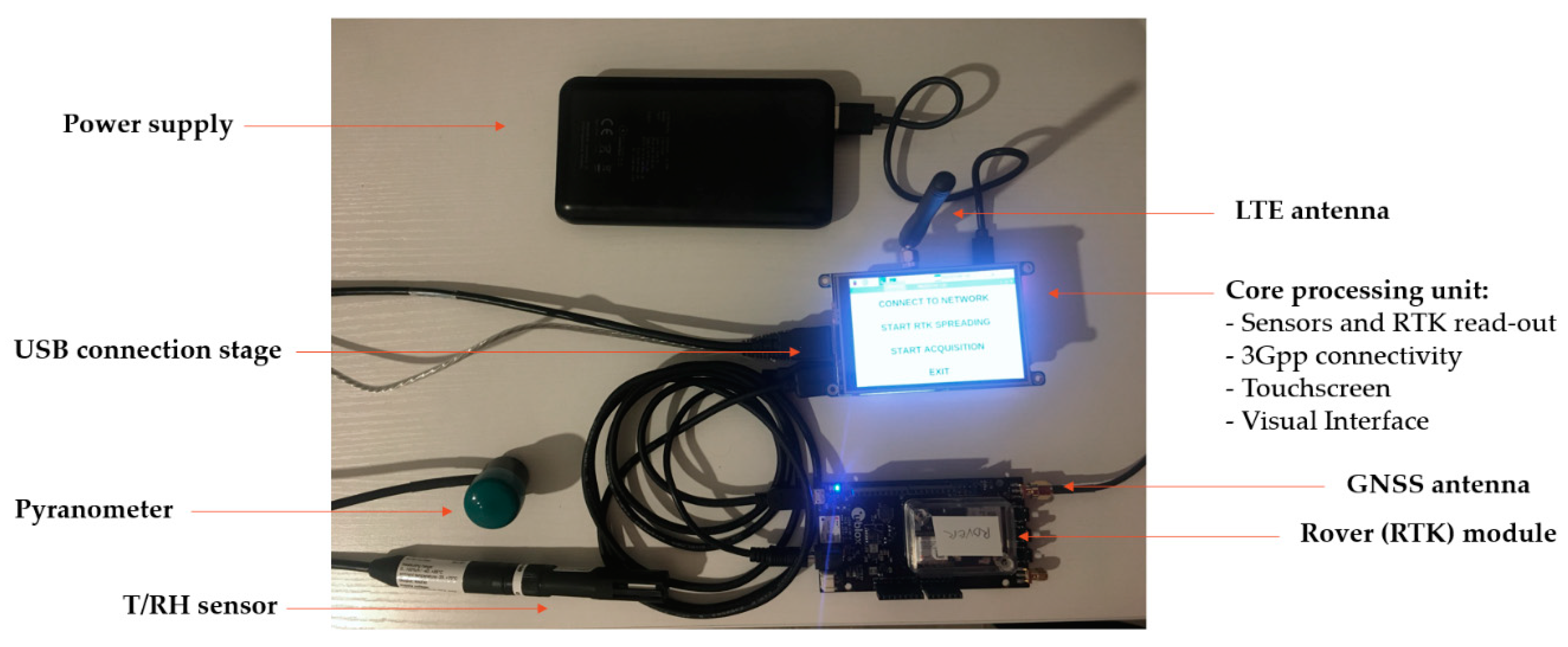
A picture of the low-cost prototype’s inner components is shown in
Figure 1. Even though the U-blox ® C099-F9P board by itself has good capabilities, we decided to give more flexibility and computational power to the prototype by coupling it with a RPi. The connection of the GNSS module to the RPi has been achieved though serial communication. The RPi as a development platform allows for many possible upgrades of the prototype, including, among others, the chance to exploit a 3/4G expansion shield for cellular connectivity, or the availability of many connection buses to couple the prototype with other sensors (temperature/relative humidity and solar radiation in the picture). The system is powered by a 5V- 15000 mAh USB power bank, which ensures its long lasting operation capabilities and portability, once fully charged. All the hardware components, besides the ANN-MB- 00 multi-band GNSS antenna and ground plate, have been enclosed within an IP68 case.
2.2. Filed Tests and Data Processing Workflow
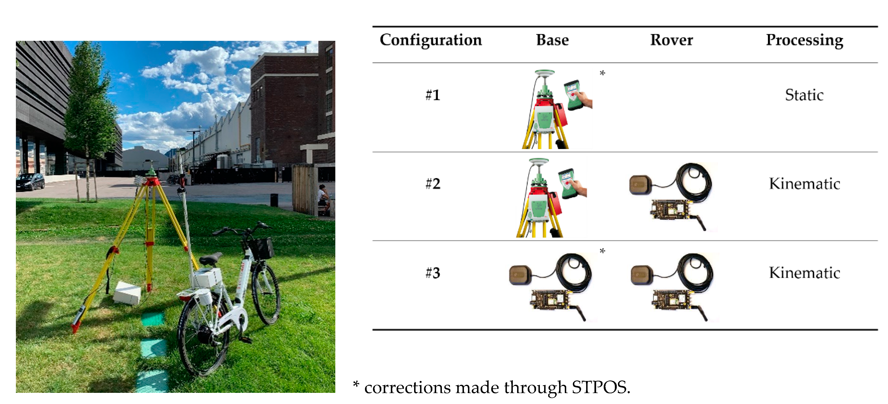
Figure 2 shows the filed campaign setup (left) and the three different configurations tested (right). A LEICA ® tripod has been used as the steady support for devices put in the base mode, while a city bicycle has been used as the rover carrier for the U-blox ®-based prototypes. Each configuration has been tested for approximately 1 hour of continuous acquisition, whereby the devices have been set to get GNSS data at 5Hz. To get differential corrections for configurations #1 and #3, RINEX data, from a permanent base station of the South Tyrolean Position Service (STPOS) network managed by the Geodetical Office of the Autonomous province of Bolzano, have been exploited [
12].
To run the experimental acquisition, the LEICA ® system was operated through the proprietary software SmartWorx Viva, and Geo Office has been used to convert the data to RINEX format. The command line interface (CLI) program STR2STR (part of RTKlib) was compiled in the NOOBS environment (on RPi) to log the raw GNSS data from the U-blox ®-based prototype, and RTKCONV was used to convert the receivers’ raw data to the RINEX format [
13]. Lastly, the RTKPOST was exploited in each configuration to provide positioning solutions from the collected data after conversion to RINEX. RTKlib supports many positioning solutions with GNSS for both real-time kinematic (RTK) and post-processed solutions with differential correction. To accomplish the post processing, the following steps were performed:
download of the RINEX file from the nearest STPOS base station to the test site, covering the whole duration of the measurement session;
post-processing calculation of the coordinates of the LEICA ® station (static point differential positional solution);
coordinates obtained at point 2 are used to retrieve the positions for the first kinematic session, i.e., configuration #2, with the U-blox ®-based rover. In particular, LEICA ® measurements are used both to retrieve the base coordinates (i.e., related to tripod position) and then the base coordinates are used to retrieve the rover coordinates in the differential solution;
coordinates obtained at point 2 are used when performing calculations with the RINEX files acquired from the two U-blox ®-based prototypes (configuration #3).
3. Results
The field tests took place in the industrial district of the city of Bolzano (IT). The LEICA ® high- accuracy GNSS set was placed in the inner courtyard of the NOI Technology Park, far from typical GNSS sources of disturbance. This setup was kept fixed during the tests of the #1 and #2 configurations. For configuration #3, the AS10 antenna on the LEICA ® tripod was replaced with the ANN-MB-00 multi-band GNSS antenna connected to one of the two U-blox ® receivers in the base configuration mode. The other U-blox ®-based prototype was mounted on an electric bike, which provided proper support for the antenna (the aluminum pole in
Figure 2) in order to place the antenna in a position not affected by the head of the driver during the tests. According to this experimental design, kinematic tests (involving moving rover) were performed only in the #2 and #3 tests. In the following section, the results obtained from the three configurations sketched in
Figure 2 are reported and discussed.
3.1. Configuration #1
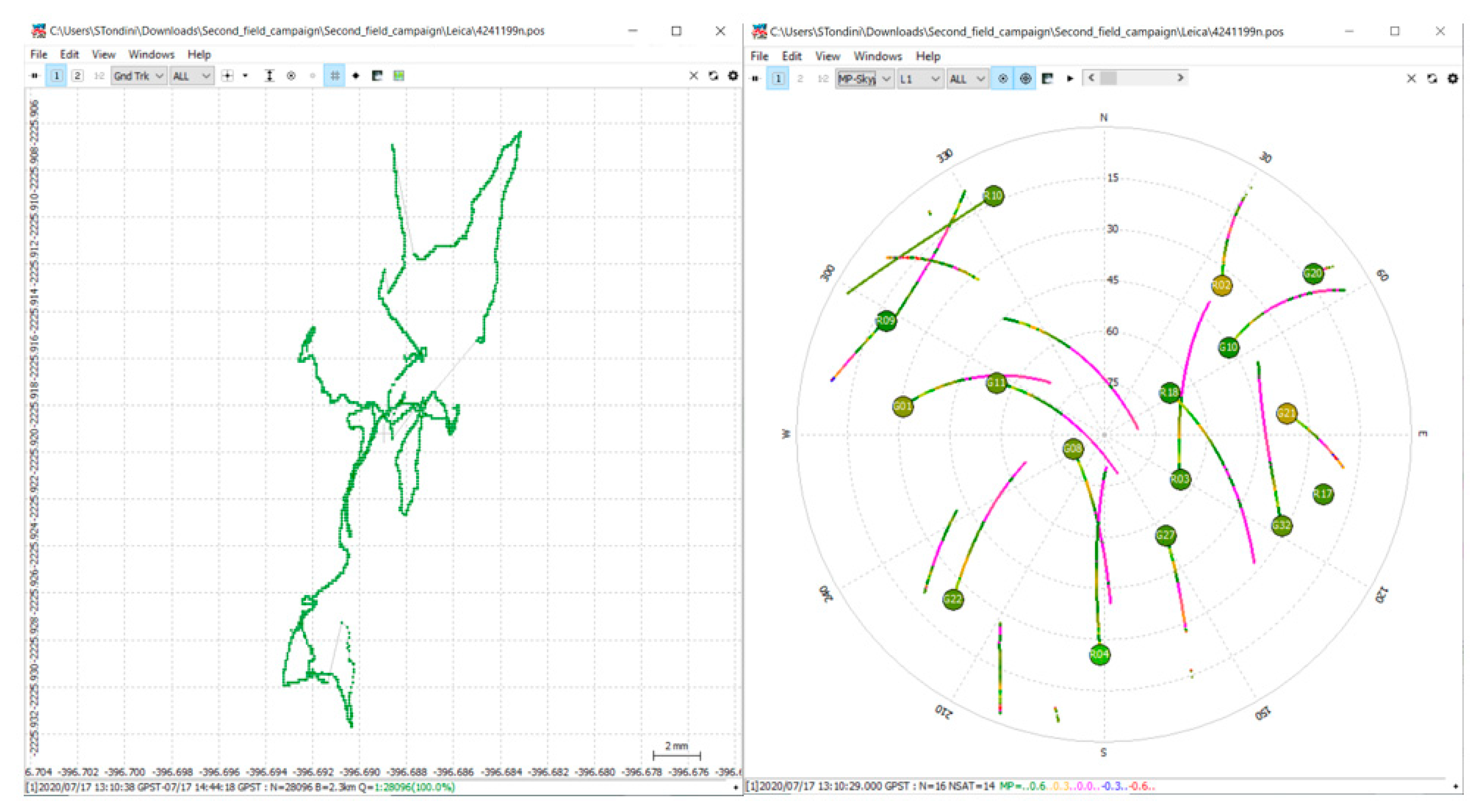
Figure 3 shows the Ground Track plot (left) and the Skyplot view of the satellites (right) obtained with RTKplot after the post-processing of the first dataset from the LEICA ® GNSS system.
3.2. Configuration #2 and #3
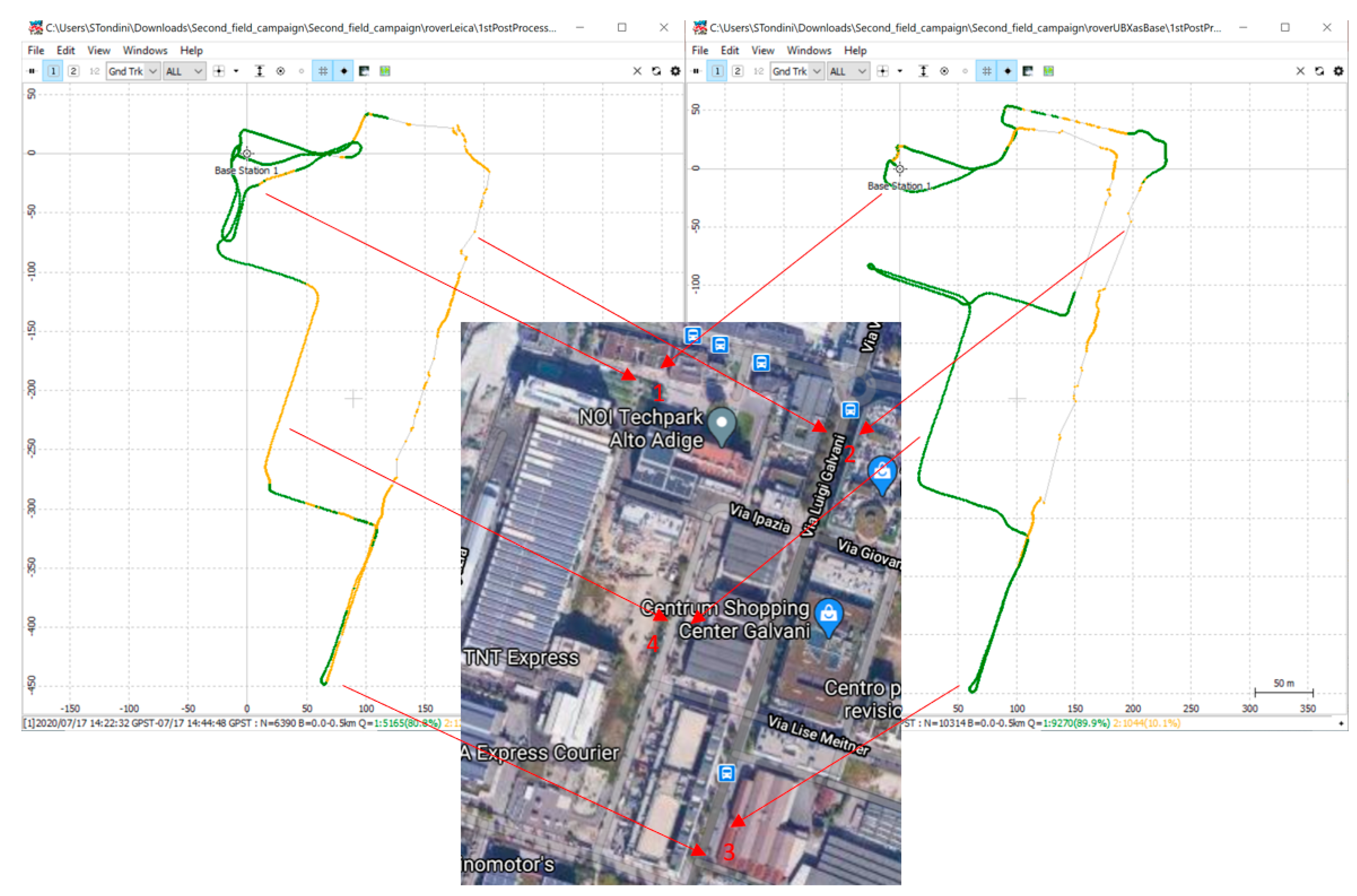
The field survey paths performed with the rover in the #2 and #3 configurations are shown in
Figure 4. The green and yellow dots represent the fixed and floating positional solutions, respectively.
3.3. Outcomes Discussion
Configuration #1 is showing the 100% fixed solution, as is expected from such a setup. During the test, GPS (US), GALILEO (EU), GLONASS (Russia) and BEIDOU (China) constellations were acquired. This allowed a good availability of satellites, and redundancy. The post processing (see
Section 2.2, point list 2) led to the following coordinates: lat. 46.4790, long 11.3316 and height 298.9675 m. Standard deviations from the .pos file obtained through RTKPOST are reported in
Table 1.
The coordinates achieved can be converted using the cartographic reference system UTM32N (EPSG:6707) through the PyProj python library [
14].
The ratio between fixed/floating solutions has been considered as an indicator of the performance for the configuration with differential corrections (#2 and #3). From a rough comparison between the two tests, we see that the #2 configuration has achieved 80.8% fixed solutions, while configuration #3 has achieved 89.9% fixed solutions. Despite this significant imbalance, we cannot assess that one configuration is better than the other because the tests have not been carried out at the same time, or following the exact same path. However, some common behaviors, encountered in both tests as referred to in the numbering in the inset of
Figure 4, can be highlighted:
(point 1) a fast convergence toward fixed solutions is reached near the base station, due to the open sky condition within the NOI Techpark courtyard and the low driving speed allowed;
(point 2) the longest straight path on the right side of the Ground Track plots is the one with the biggest amount of unfixed solutions, due to the fact that the cycle lane is mostly covered by the tree canopy and is close to the building’s walls (which is preventing a good signal to be acquired);
(point 3) even with the limited sky view factor, the amount of fixed solutions increases rapidly with the decreasing the speed of the rover, at the about-turn point, for instance;
(point 4) multipath effects can also be detrimental, turning into floating solutions when driving along buildings and canyon walls.
However, the preliminary tests carried out show that a similar accuracy can be reached in near- real-time kinematics even when a low-cost base station is involved to get differential correction.
4. Conclusions
The achieved results confirm that the approach is suitable for urban monitoring mobile applications, where several nodes can be installed, for instance, on public transport vehicles (commercial average speed below 40 km/h), to expand the spatio-temporal resolution (centimeter- level accuracy in seconds) of environmental data, while keeping low the number of sensors to deploy. Significant accuracy might be expected using low-cost devices with inertial measurement unit (IMU) capabilities.
The future outlook involves the assessment of statistic correlations between local microclimatic conditions, urban surface usage and urban morphology to aid in the development of sustainable energy and climate action plans at the municipality level.
Author Contributions
Conceptualization, A.N.; methodology, A.N. and S.T.; software, F.H.; validation, S.T. and F.H.; formal analysis, F.H.; investigation, S.T.; resources, S.T.; data curation, F.H.; writing—original draft preparation, S.T.; writing—review and editing, F.H., A.N. and R.M.; visualization, S.T.; supervision, R.M.; project administration, S.T.; funding acquisition, R.M. All authors have read and agreed to the published version of the manuscript.
Funding
The research leading to these results has received funding from the European Regional Development Fund, Operational Programme Investment for growth and jobs ERDF 2014-2020 under Project number ERDF1094, Data Platform and Sensing Technology for Environmental Sensing LAB—DPS4ESLAB.
Acknowledgments
The authors would like to thank the NOI Techpark facility management for easing the experimental campaigns inside and outside the Technology Park area.
Conflicts of Interest
The authors declare no conflict of interest. The funders had no role in the design of the study; in the collection, analyses, or interpretation of data; in the writing of the manuscript, or in the decision to publish the results.
References
- Argüeso, D.; Evans, J.P.; Pitman, A.J.; Di Luca, A. Effects of City Expansion on Heat Stress under Climate Change Conditions. PLoS ONE 2015, 10, e0117066. [Google Scholar] [CrossRef] [PubMed]
- Khashoggi, B.F.; Murad, A. Issues of Healthcare Planning and GIS: A Review. ISPRS Int. J. Geo-Inf. 2020, 9, 352. [Google Scholar] [CrossRef]
- Liu, Q.; Ullah, H.; Wan, W.; Peng, Z.; Hou, L.; Qu, T.; Ali Haidery, S. Analysis of Green Spaces by Utilizing Big Data to Support Smart Cities and Environment: A Case Study About the City Center of Shanghai. ISPRS Int. J. Geo-Inf. 2020, 9, 360. [Google Scholar] [CrossRef]
- Hayashi, S.; Takahashi, H.; Abe, T.; Chiba, S.; Suganuma, T. An Estimation Method of Urban Microclimate Using Mobile IoT Environment Sensors. In Proceedings of the 2019 IEEE 8th Global Conference on Consumer Electronics (GCCE), Osaka, Japan, 15–18 October 2019; pp. 642–643. [Google Scholar]
- Pulighe, G.; Baiocchi, V.; Lupia, F. Horizontal accuracy assessment of very high-resolution Google Earth images in the city of Rome, Italy. Int. J. Digital Earth 2016, 9, 342–362. [Google Scholar] [CrossRef]
- Aguilar, M.A.; Nemmaoui, A.; Aguilar, F.J.; Novelli, A.; García Lorca, A. Improving georeferencing accuracy of Very High Resolution satellite imagery using freely available ancillary data at global coverage. Int. J. Digital Earth 2017, 10, 1055–1069. [Google Scholar] [CrossRef]
- Robustelli, U.; Baiocchi, V.; Pugliano, G. Assessment of Dual Frequency GNSS Observations from a Xiaomi Mi 8 Android Smartphone and Positioning Performance Analysis. Electronics 2019, 8, 91. [Google Scholar] [CrossRef]
- Liu, T.; Li, B. Single-frequency BDS/GPS RTK with low-cost U-blox receivers. In Proceedings of the 2017 Forum on Cooperative Positioning and Service (CPGPS), Harbin, China, 19–21 May 2017; pp. 232–238. [Google Scholar]
- C099-F9P Application Board. Available online: https://www.u-blox.com/en/product/c099-f9p-application- board (accessed on 14 October 2020).
- Raspberry Pi 4. Available online: https://www.raspberrypi.org/products/raspberry-pi-4-model-b/ (accessed on 14 October 2020).
- RTKLIB: An Open Source Program Package for GNSS Positioning. Available online: http://www.rtklib.com/ (accessed on 14 October 2020).
- STPOS South Tyrolean Position Service. Available online: http://www.provincia.bz.it/it/servizi-a- z.asp?bnsv_svid=1008891#accept-cookies (accessed on 14 October 2020).
- RTKLIB ver. 2.4.2 Manual. Available online: http://www.rtklib.com/prog/manual_2.4.2.pdf (accessed on 14 October 2020).
- pyproj Documentation—pyproj 2.6.1 Documentation. Available online: http://pyproj4.github.io/pyproj/stable/ (accessed on 14 October 2020).
| Publisher’s Note: MDPI stays neutral with regard to jurisdictional claims in published maps and institutional affiliations. |
© 2020 by the authors. Licensee MDPI, Basel, Switzerland. This article is an open access article distributed under the terms and conditions of the Creative Commons Attribution (CC BY) license (https://creativecommons.org/licenses/by/4.0/).


