1. Introduction
Throughout the world there is a large number of civil and mechanical structures, such as urban infrastructures and large means of transport, in constant use by the population, that can suffer damage due to wear and environmental influences. Therefore, the detection of damage at an early stage on these structures is of global interest, as it permits the reduction of maintenance costs and provides security to users.
For this purpose, structural health monitoring (SHM) systems have been investigated [
1,
2]. Such systems should monitor the structure, preferably in real time or periodically, and detect structural damage before its performance is impaired and the safety of users is at risk. Although SHM systems can be used on a wide variety of structures, studies reported in the literature have mainly focused on aeronautical structures [
3] and civil infrastructures [
4].
In order for the structure not to be impaired during monitoring, damage detection must be performed using a non-destructive testing (NDT) technique which is minimally invasive to the monitored structure. There are many NDT techniques reported in the literature that can be applied to SHM systems, such as Lamb waves [
5] and acoustic emissions [
6]. In this work, structural damage detection is based on the electromechanical impedance (EMI) technique, which uses piezoelectric transducers attached to the monitored structure operating simultaneously as both sensor and actuator [
7].
This technique is usually performed at low frequencies, below 500 kHz. Recent studies indicate, however, that piezoelectric transducers should be excited at high frequencies, generally higher than 1 MHz, for the detection of some types of damage or to monitor some characteristics of the structure [
8]. As such, an analysis of piezoelectric transducers at high frequencies is necessary. Therefore, the performance of piezoelectric transducers excited with high frequency signals for structural damage detection based on the electromechanical impedance is analyzed in this work.
2. Electromechanical Impedance Technique
As mentioned previously, damage detection based on the EMI technique consists of attaching a piezoelectric transducer to a structure to be monitored. The transducer’s impedance signatures as a function of frequency are obtained for the structure at a healthy state, and for a state in which the structure is possibly damaged.
There are several models which have been proposed to relate the transducer’s electrical impedance and the structure’s mechanical impedance. For thin transducers and small structures, as is this work’s case, a one-dimensional model is satisfactory, so that the electrical impedance of the piezoelectric transducer attached to the structure is given by [
9]:
where
is the transducer’s electrical impedance,
is the monitored structure’s mechanical impedance,
is the transducer’s mechanical impedance,
is the frequency,
is the transducer’s capacitance,
is the imaginary unit,
is the piezoelectric constant,
is the elastic compliance and
is the dielectric constant. The superscripts
and
indicate constant electric field and constant stress, respectively, and the subscripts 1 and 3 represent the axes of the natural coordinate system of the piezoelectric material under the one-dimensional assumption.
According to Equation (1), any variation in the structure’s mechanical impedance caused by structural damage will result in a corresponding variation in the transducer’s electrical impedance. Therefore, the structure’s integrity can be monitored by measuring and analyzing the transducer’s electrical impedance.
Typically, damage detection is performed through damage indices, comparing two impedance signatures. One is obtained for a healthy state of the structure and is used as reference (baseline), while the other signature is obtained during the monitoring of the structure. One of the damage indices used in this work is the root mean square deviation (RMSD), based on the Euclidean norm, which is given by [
2]:
where
is the impedance signature obtained for a healthy state of the structure and
is the impedance signature obtained during the monitoring of the structure,
fI is the initial frequency, and
fF is the final frequency.
The other damage index used in this work is the correlation coefficient deviation metric (CCDM), based on the correlation coefficient, which is given by [
10]:
where
and
are the impedance signatures’ mean values obtained for a healthy state of the structured and during the monitoring of the structure, respectively. In this work, the real part of the impedance signatures was used.
In the next section, the experimental setup used to verify the transducer’s performance for damage detection at high frequencies is presented.
3. Experimental Setup
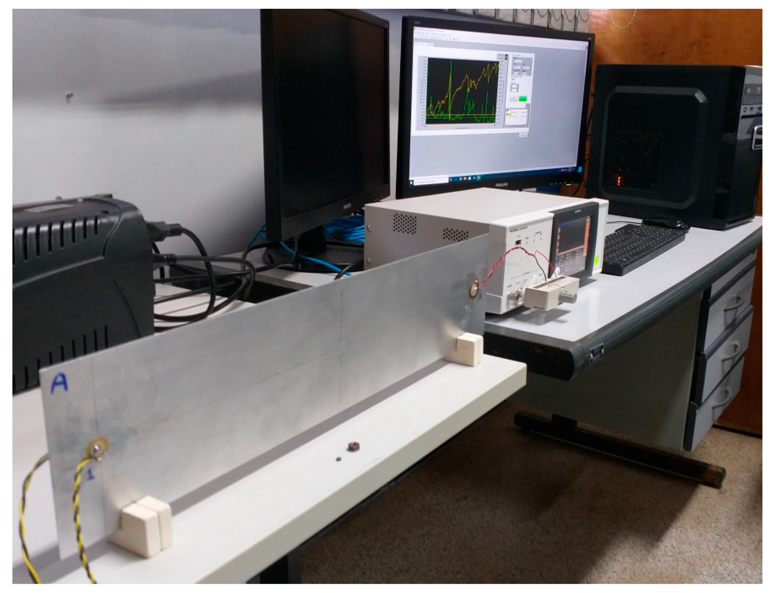
To verify the piezoelectric transducer’s sensitivity to damage detection at high frequencies, two aluminum plates were used as structures to be monitored, one with dimensions of 500 mm × 119 mm × 1 mm (Structure A) and the other with dimensions of 304 mm × 196 mm × 1 mm (Structure B), supported by rubber blocks. In this study, low-cost piezoelectric diaphragms, which are sound components mass-produced by several manufacturers, were evaluated. Three types of piezoelectric diaphragms were used as transducers, all from Murata Manufacturing, as follows: a 7BB-15-6, with an active piezoelectric element with a diameter of 10 mm; a 7BB-20-6, with an active piezoelectric element with a diameter of 14 mm; and a 7BB-35-3, with an active piezoelectric element with a diameter of 25 mm. One transducer of each type was attached to each structure using cyanoacrylate adhesive, so that all diaphragms were at the center of the plate and 50 mm from one of the plate’s ends. Structural damage was simulated by means of attaching two steel nuts to the structures, one with dimensions of 9 mm × 4 mm (Large Damage) and the other with dimensions of 4 mm × 1.5 mm (Small Damage). The nuts were used one at a time, coupled to the structure at its center point. The experimental setup is shown in
Figure 1.
To measure the transducers’ electrical impedance, an IM3536 LCR meter from HIOKI connected to a personal computer was used, with an excitation voltage of 0.06 Vrms. A low voltage was chosen so that the high frequency current was within the limits of the LCR meter. The transducers’ impedance signatures were obtained for low frequencies, in a range from 60 kHz to 80 kHz, and for high frequencies, in a range from 1 MHz to 1.2 MHz, in order to compare their performances in both situations. With the impedance signatures, the RMSD and CCDM indices were calculated in sub-bands of 1 kHz for low frequencies, and in sub-bands of 10 kHz for high frequencies. The obtained results are presented and discussed in the next section.
4. Results and Discussion
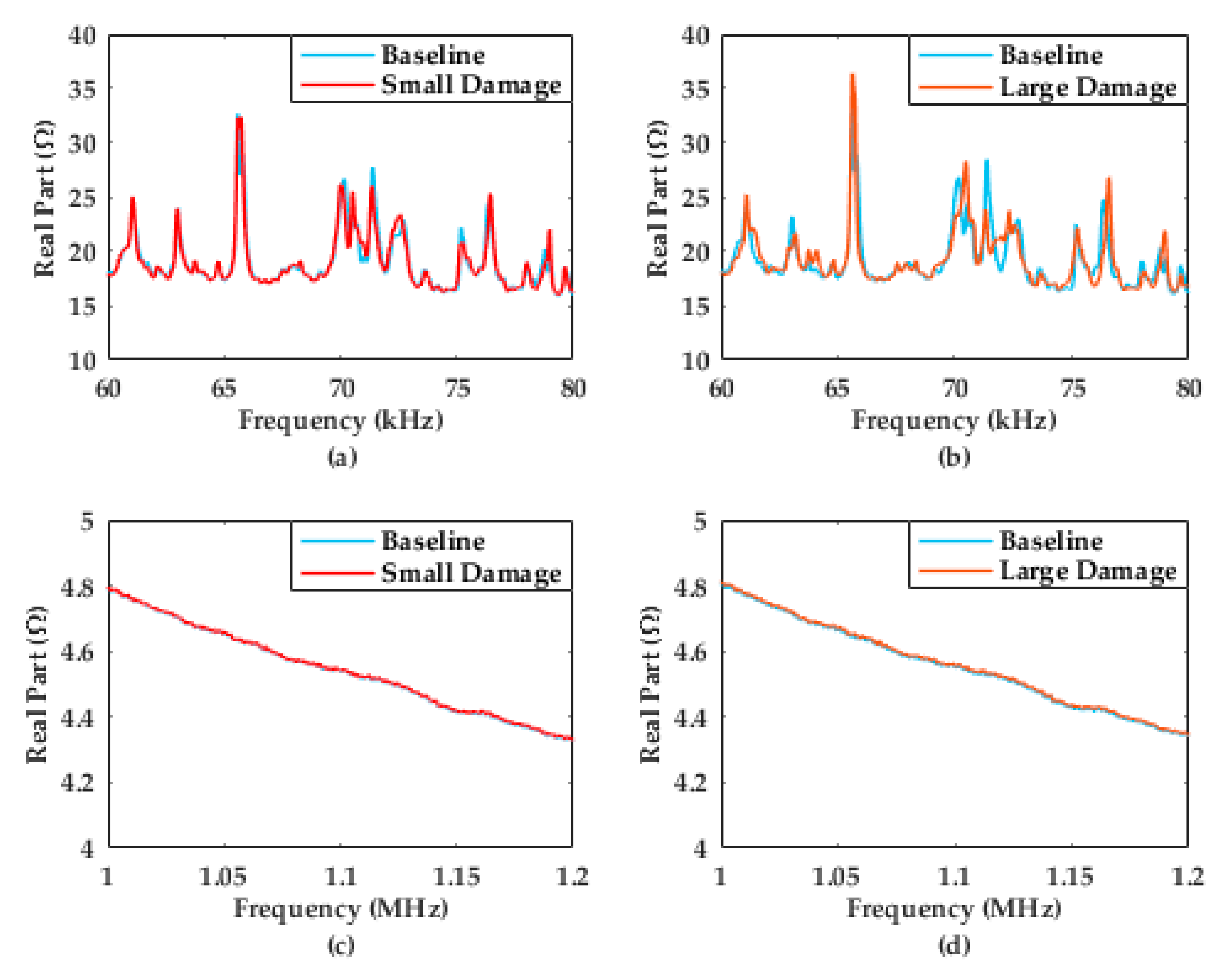
As mentioned previously, structural damage changes the transducer’s electric impedance, causing the electrical impedance signature to change in relation to the baseline. This can be seen in
Figure 2, which shows the real part of the impedance signatures obtained for the largest transducer on Structure B, for both low and high frequencies and for small and large damages.
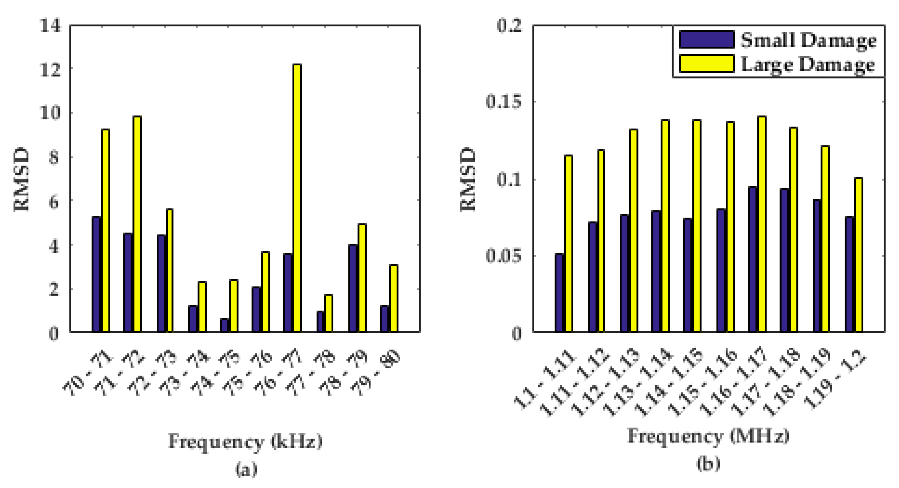
Figure 3 shows the calculated RMSD indices for the same situation described above.
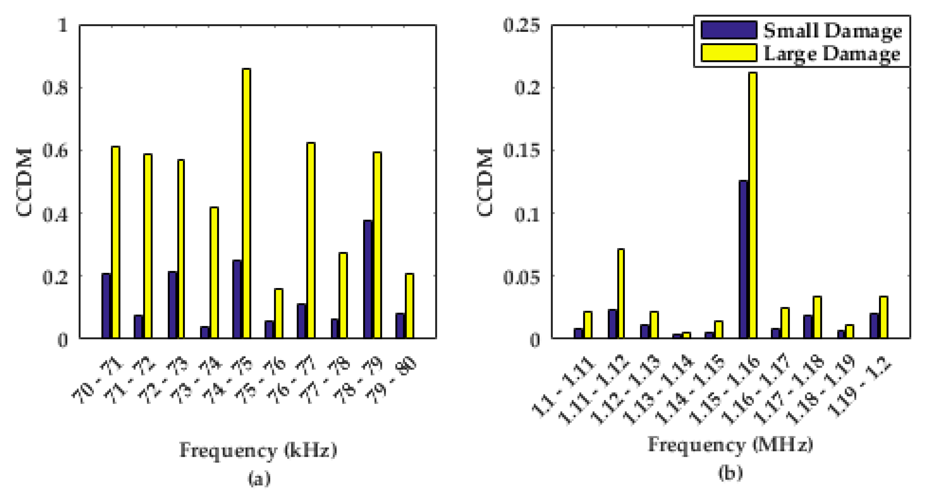
Figure 4 shows the calculated CCDM indices for the same situation described above.
The RMSD and CCDM indices are presented in the range from 70 kHz to 80 kHz for low frequency and in the range from 1.1 MHz to 1.2 MHz in order to facilitate the visualization and comparison of the results.
As can be seen in
Figure 2, there is almost no qualitative difference between the baseline and the impedance signature for the damaged structure at high frequency, for both damages. However, variations in the impedance signatures can be quantitatively observed by calculating damage indices.
In
Figure 3 and
Figure 4, we can see that the RMSD and CCDM indices calculated at low frequencies were considerably higher than those calculated at high frequencies, for both damages. This result pattern was observed for all transducers on both structures. Therefore, it is seen that piezoelectric diaphragms are capable of detecting and quantifying damage at high frequencies, but the sensitivity is significantly lower.
5. Conclusions
This work presents a comparative analysis between the piezoelectric diaphragms’ sensitivity for structural damage detection at low and high frequencies in SHM systems based on the electromechanical impedance technique. Two aluminum plates were used as structures to be monitored, each with three transducers of different sizes. Two degrees of damage were simulated on the structures and the transducers’ electrical impedance signatures were obtained for low and high frequencies.
The damage indices obtained at high frequencies were lower than those obtained at low frequencies. However, despite the low values, these indices vary according to the size of the structural damage. Therefore, the experimental results indicate that piezoelectric diagrams are capable of detecting and quantifying structural damage at high frequencies, although the sensitivity is lower compared to low frequencies.


