1. Introduction
According to the World Health Organization [
1], over 15 billion injections are administered worldwide each year. Despite their routine nature, these procedures pose significant health risks to medical personnel due to accidental needlestick injuries. It is estimated that approximately 3 million such injuries occur annually, often resulting in the transmission of serious infections including Hepatitis B, Hepatitis C and HIV. Therefore, the biological hazard associated with needlestick injuries represents a major occupational concern, since they may occur during syringe use, disassembly or disposal [
1,
2,
3,
4]. To mitigate these risks, in 2014, the Italian government prohibited the manual recapping of needles in the absence of protective devices [
5]. Furthermore, the increased workload during the COVID-19 pandemic and the mandatory use of personal protective equipment, which limited the mobility of healthcare personnel, further highlighted the urgent need for secure, user-friendly and rapid procedures to ensure both operator safety and clinical efficiency [
6].
Various syringe systems presenting needle protection mechanisms have been invented with the scope of preventing accidental needlestick injuries. For instance, Patent no. US10661026B2 [
7] presents a housing fixed to the syringe that extends to cover the needle tip after injection with the aid of a spring mechanism. Patent no. US10589036B2 [
8] describes a similar solution, with a retractable sheath that moves along three possible guide paths. The device operates passively, with a spring element that automatically extends the sheath after injection. Patent no. US11058826B2 [
9] relates to a prefilled vaccination syringe with a spring-driven retractable needle system. A multi-fingered retainer secures the needle to prevent premature retraction before plunger activation. A locking mechanism ensures the needle remains retracted once the injection process is concluded. Patent no. US9931475B2 [
10] proposes a kit with a retractable needle designed to be attached to the front of the syringe. The system uses a spring mechanism and pinch-activated lateral movement to quickly and simply retract the needle into a dedicated cavity. Patent no. US11173254B2 [
11] introduces a shield mechanism that encloses the needle when it is not used. The shield retracts toward the device body to expose the needle for use and then returns to its original position. Patent no. US5407431A [
12] outlines a hypodermic injection system with a retractable needle that is securely contained within an interior cavity of the syringe plunger after use. A spring-loaded mechanism, held by resilient fingers, is activated when the plunger frangible end breaks, so that the needle and its holder can retract safely into the plunger. The solution in Patent no. US5338304A [
13] involves a compressive member to induce needle retraction into a protective cover.
The solutions described above are expensive and complex to implement and use. A patent of particular interest is ITUB20160423A1 [
14], which presents a retractable needle system integrated into a tubular vial. One end of the vial is sealed with a perforable rubber diaphragm, while the other is closed by a sliding plunger. The needle presents temporary locking mechanisms that enable its connection to a threaded sleeve and to the plunger. This configuration allows the needle to be disengaged and safely retracted by moving the plunger backward. The needle retraction and locking are achieved through the presence of two air chambers that help absorb and redirect the force exerted during the final phase of injection. This reduces the force required to lock the needle into place and makes the process smoother and safer for the operator. Although the retraction mechanism is manual, the system is robust and well-suited for autoclavable syringes.
This manuscript presents the patented solution described in IT202200006635A1 [
15] (Italian grant obtained on 20 March 2024 and Unitary—European grant obtained on 10 December 2025, number: EP4504302) for a multi-injection syringe designed to significantly reduce the risk of disease transmission caused by accidental contact with contaminated needles. The device is intended to be used in a wide spectrum of medical fields, including dentistry, surgical specialties, veterinary medicine, blood sampling and intramuscular injections. Unlike conventional syringes that present removable plastic covers, the present invention offers a safer and more reliable alternative. It integrates a retractable hypodermic needle with assisted actuation, which ensures a safe return of the needle into the syringe frame after each injection. Once all the fluid has been injected, the needle retracts entirely into the tube vial, so that the risk of accidental puncture during its removal is completely eliminated. The system is a syringe of the type described in Patent no. GB457152A [
16], dated 1936. The novelty of the device described in this manuscript lies in the presence of at least one flexural spring which, combined with at least one spring, provides needle movement and secure locking in multiple positions. This innovative configuration distinguishes the patented solutions from prior art and enhances safety in clinical operations. By preventing human-to-human and animal-to-human transmission of infectious agents, the system addresses a critical safety concern in clinical practice in a cost-effective manner, thanks to a limited number of components, some of which are reusable.
2. Description of the Invention and Advantages
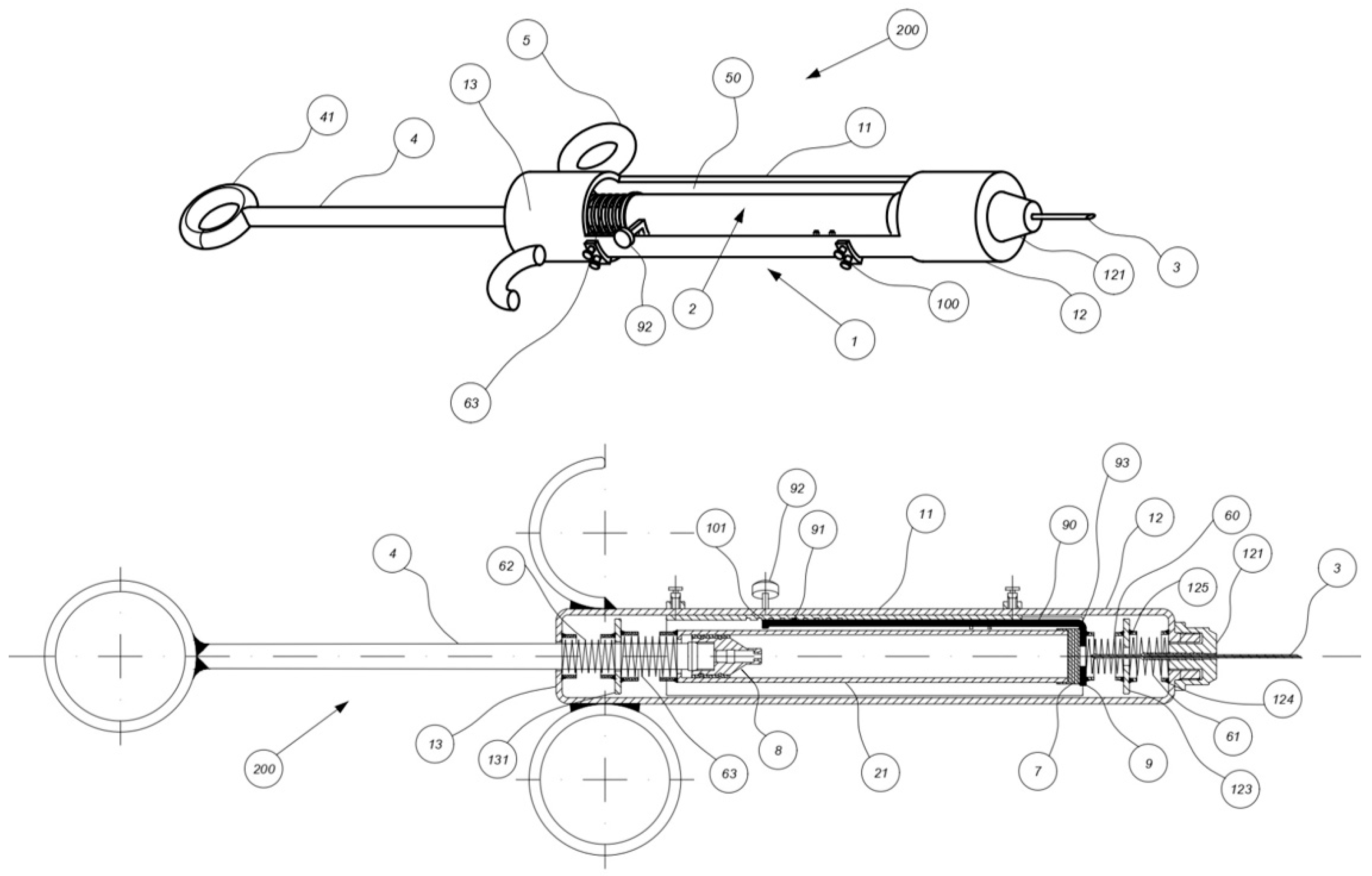
The system consists of a hollow cylindrical supporting frame (1 in
Figure 1) with a cylindrical body which contains a tube vial (2) filled with the injectable fluid. The vial is sealed at the front by a rubber diaphragm (7) and at the rear by a plunger (8). A stem (4) with a handle (41) slides through the bottom of the frame to actuate the plunger. The syringe supports the hypodermic needle (3) at its front end. In
Figure 1, the syringe head contains two front springs (60 and 61) and a movable perforated plate (123) that assist the movement of the needle; the bottom section similarly houses two rear springs (62 and 63) and a second perforated plate (131), which supports the rear end of the tube vial and contributes to its axial balance within the frame. The figure shows one possible configuration of the system that includes four springs. However, the needle return mechanism can generally be implemented with at least one spring. The key innovation is the inclusion of at least one flexural spring (90) which can be fixed to a plate adjacent to the diaphragm. This spring, equipped with a knob (92) and at least one locking tooth (91), is flexible in the radial and circumferential directions and interacts with a support structure (100) presenting multiple cavities (101), each shaped to engage with the tooth/teeth of the flexural spring. By flexing and rotating the knob, the user can lock or unlock the spring and place it in various axial positions, controlling the movement of the tube vial and needle.
The invented syringe operates through the following steps, with minor variations allowed depending on use case and design configuration:
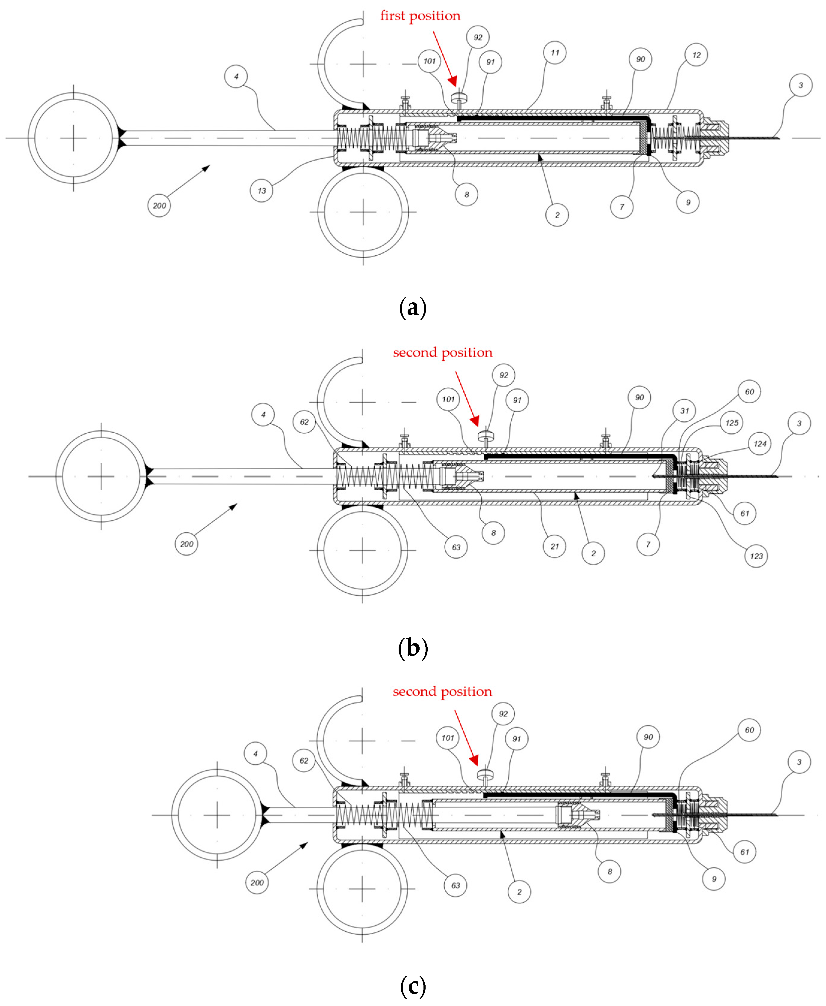
Initial position (
Figure 2a): The needle (3) partially protrudes from the head of the syringe and the flexural spring (90) is locked in a first position.
Needle–vial connection (
Figure 2b): The user unlocks the flexural spring (90) and compresses the front springs (60 and 61), so that the tube vial (2) advances and the needle (3) pierces the diaphragm (7). The flexural spring is then locked in a second position.
First injection (
Figure 2c): The stem (4) pushes the plunger (8) causing the injection of the fluid through the needle (3).
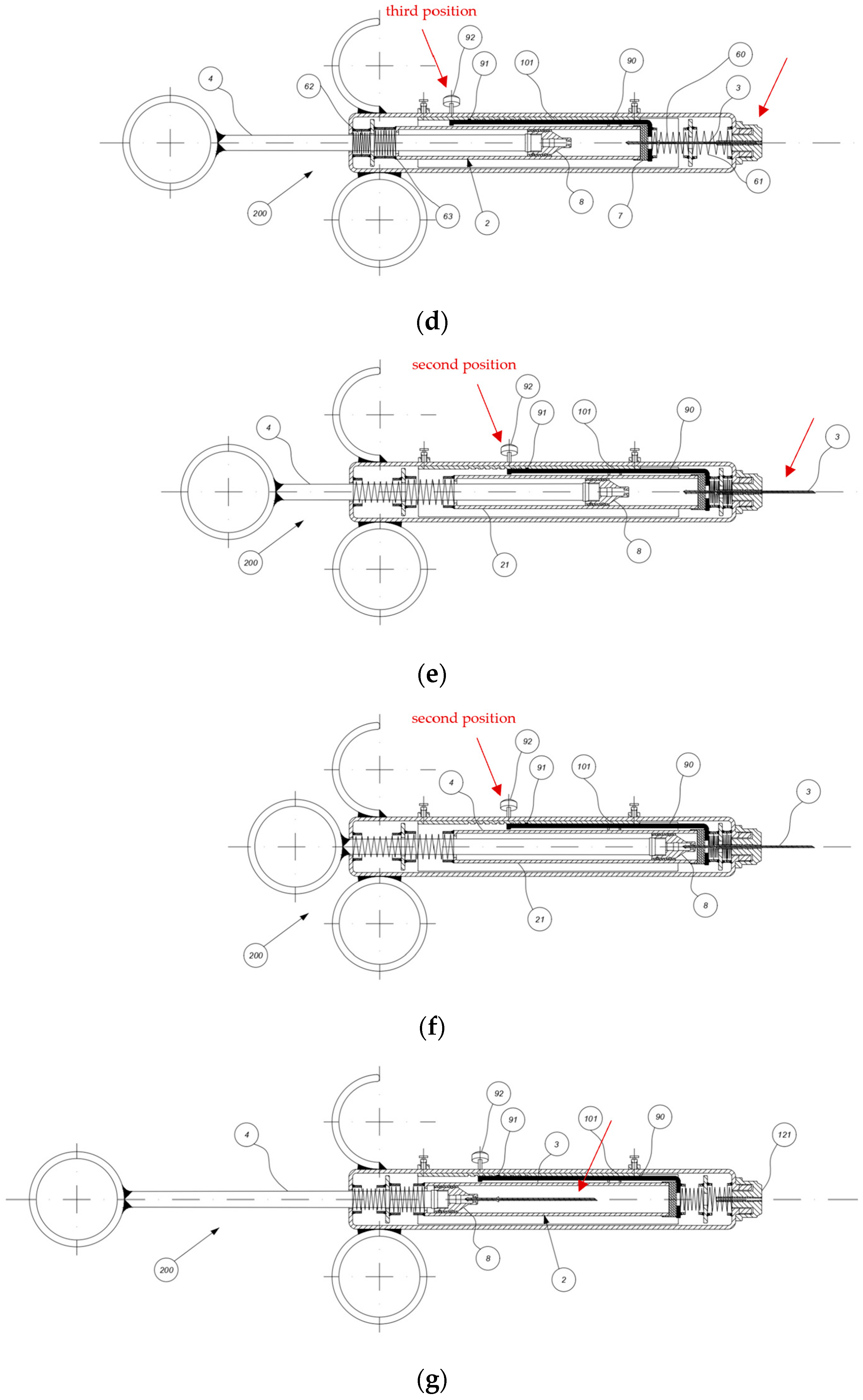
First retraction (
Figure 2d): After injection, the user unlocks the flexural spring (90) again, allowing the needle (3) and tube vial (2) to retract. The spring is then locked in a third position so that the needle is fully retracted into the frame, avoiding accidental punctures.
Positioning for subsequent injections (
Figure 2e): Operations 3 and 4 can be repeated for multiple injections. The user unlocks the flexural spring (90) and compresses the front springs again so that the tube vial advances. The flexural spring is then locked in the second position and the needle (3) once again partially protrudes from the syringe head, enabling further injections.
Emptying (
Figure 2f): The tube vial is completely emptied. At the end of the process, the plunger (8) couples with the rear end of the needle (3) as described in [
14].
Final position of the needle for vial replacement (
Figure 2g): The stem (4) is fully retracted, pushing the plunger (8) backward. The needle (3) is now completely housed within the vial (2), allowing for safe replacement of the vial and needle without risk of accidental puncture.
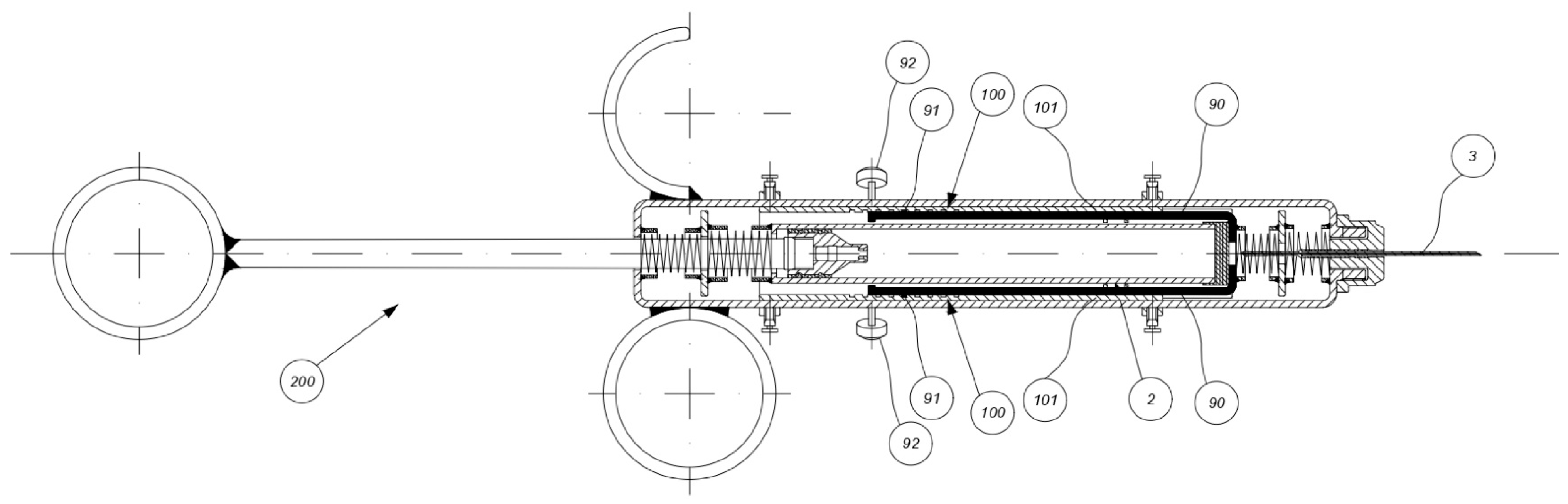
A possible configuration of the syringe system includes two flexural springs (
Figure 3).
The manufacturing process of the syringe system must ensure precision, repeatability and compatibility with large-scale industrial production. The components can be fabricated using conventional technologies that are widely adopted in the medical device sector, enabling cost-effective production while meeting stringent safety and hygiene requirements. The tube vial is typically manufactured from glass or polymeric materials, whereas the diaphragm is produced from elastomers through molding processes. The plunger is molded from elastomeric compounds. The needle is fabricated from stainless steel and its geometry must be controlled to allow coupling with the diaphragm or the plunger during the different operational phases of the injection. The syringe frame can be produced from metallic or polymeric materials using conventional manufacturing technologies such as molding combined with machining or, alternatively, additive manufacturing. Its geometry must accommodate the support structure and the flexural spring(s), which can be produced with metallic materials. Due to the small dimensions of such components, particularly the locking tooth/teeth on the flexural spring and the corresponding cavities in the support, strict dimensional tolerances are required to ensure reliable engagement. The springs can be metallic and must be manufactured with adequate stiffness and fatigue resistance. The plates, when present, may be produced from metallic or polymeric materials. The syringe undergoes sterilization using technologies compatible with the selected materials. Since the device does not contain any mechatronic components, sterilization using fluids is also feasible.
The proposed syringe system presents several advantages that make it a valuable innovation in the field of medical devices. First of all, its design offers enhanced protection against accidental needlestick injuries, improving safety conditions for healthcare operators. Recent patent activity in retractable needle technologies reflects the growing scientific and industrial focus on this issue. The proposed solution addresses this urgent need with a user-centered design that ensures ease of use without compromising performance or user mobility. The presence of a limited number of components, some of which are reusable like the syringe frame, guarantees moderate production cost and reduced medical waste, promoting sustainable healthcare practices.
The innovative needle actuation mechanism differs from conventional syringe operations and for this reason requires users to adapt to new handling techniques. However, the invention offers promising opportunities. Its adaptable design allows for potential application across diverse medical specialties, with only minor modifications needed to accommodate specific user preferences. Moreover, the underlying mechanism of assisted needle retraction could be extended to other industrial domains where precision and safety are paramount.
3. Conclusions
This manuscript describes a patented solution for a multi-injection syringe presenting a retractable needle mechanism actuated by at least one spring and one flexural spring. The system offers enhanced protection against needlestick injuries while maintaining ease of use. Its simple design, reusability and adaptability make the syringe suitable for a broad range of medical applications. By addressing critical safety concerns, this invention contributes meaningfully to the advancement of injection technologies.
4. Patents
The invention described in this manuscript is the subject of the patent entitled “Multiple injection syringe with retractable needle and assisted needle actuation for injection and return”. The relevant data are as follows:
Application number (Italy): 102022000006635.
Application date: 04/04/2022.
PCT application number: PCT/EP2023/057222.
PCT application date: 21/03/2023.
Inventors: Sergio Baragetti, Stefano Paleari, Emanuele Vincenzo Arcieri.
Published as WO2023194097A1.
Italian grant date: 20/03/2024.
Unitary—European grant date: 10/12/2025.
Unitary—European number: EP4504302.
Author Contributions
Conceptualization, S.B., S.P. and E.V.A.; methodology, S.B., S.P. and E.V.A.; software, S.B., S.P. and E.V.A.; validation, S.B., S.P. and E.V.A.; formal analysis, S.B., S.P. and E.V.A.; investigation, S.B., S.P. and E.V.A.; resources, S.B., S.P. and E.V.A.; data curation, S.B., S.P. and E.V.A.; writing—original draft preparation, E.V.A.; writing—review and editing, S.B. and S.P.; visualization, S.B., S.P. and E.V.A.; supervision, S.B., S.P. and E.V.A.; project administration, S.B. and S.P. All authors have read and agreed to the published version of the manuscript.
Funding
This research received no external funding.
Institutional Review Board Statement
Not applicable.
Informed Consent Statement
Not applicable.
Data Availability Statement
No new data were created or analyzed in this study. Data sharing is not applicable to this article.
Conflicts of Interest
The authors declare no conflicts of interest.
References
- World Health Organization. WHO Guideline on the Use of Safety-Engineered Syringes for Intramuscular, Intradermal and Subcutaneous Injections in Health Care Settings; WHO: Geneva, Switzerland, 2016; Available online: https://www.who.int/publications/i/item/9789241549820 (accessed on 18 June 2020).
- Prüss-Ustün, A.; Rapiti, E.; Hutin, Y.J.F. Sharps Injuries: Global Burden of Disease from Sharps Injuries to Health-Care Workers; World Health Organization: Geneva, Switzerland, 2003; Available online: https://www.who.int/publications/i/item/9241562463 (accessed on 18 June 2020).
- Cooke, C.E.; Stephens, J.M. Clinical, economic, and humanistic burden of needlestick injuries in healthcare workers. Med. Devices Evid. Res. 2017, 10, 225–235. [Google Scholar] [CrossRef] [PubMed]
- Hasak, J.M.; Novak, C.B.; Patterson, J.M.; Mackinnon, S.E. Prevalence of needlestick injuries, attitude changes, and prevention practices over 12 years in an urban academic hospital surgery department. Ann. Surg. 2018, 267, 291–296. [Google Scholar] [CrossRef] [PubMed]
- Decreto Legislativo 19 febbraio 2014, n. 19. Gazzetta Ufficiale della Repubblica Italiana. Available online: https://www.gazzettaufficiale.it/eli/id/2014/03/10/14G00031/sg (accessed on 18 June 2020).
- Persaud, E.; Mitchell, A. Needlestick injuries among healthcare workers administering COVID-19 vaccinations in the United States. New Solut. J. Environ. Occup. Health Policy 2021, 31, 16–19. [Google Scholar] [CrossRef] [PubMed]
- Smith, P.; Sanders, L.; Browka, E.P.; Marici, P.; Nichols, E.B. Safety Needle Device. U.S. Patent 10661026B2, 11 December 2017. [Google Scholar]
- Sanders, L.; Swanson, D.; Hayes, J.; Willard, G. Safety Needle Device. U.S. Patent 10589036B2, 11 December 2017. [Google Scholar]
- Thorley, C.S.; Kaal, J.H.; Rafferty, C.C.; Johnson, I.; Siu, E.; Reade, A. Vaccination Syringe. U.S. Patent 11058826B2, 10 January 2019. [Google Scholar]
- Shaw, T.J.; Small, M.; Zhu, N. Frontal Attachment Device for Syringe with Pinch-Activated Needle Retraction. U.S. Patent 9931475B2, 5 July 2016. [Google Scholar]
- Moleda, J. Needle-Based Device with a Safety Mechanism Implemented Therein. U.S. Patent 11173254B2, 27 March 2020. [Google Scholar]
- Botich, M.J.; Halseth, T. Intravenous Catheter Insertion Device with Retractable Needle. U.S. Patent 5407431A, 27 September 1993. [Google Scholar]
- Adams, R.D. Needle Protected Syringe. U.S. Patent 5338304A, 14 September 1993. [Google Scholar]
- Mariani, U. Sistema di Sicurezza per Siringa Autoclavabile. Italian Patent UB20160423A1, 1 February 2016. [Google Scholar]
- Baragetti, S.; Paleari, S.; Arcieri, E.V. Siringa a Iniezione Multipla con Ago Retrattile e Azionamento Assistito dell’Ago per Iniezione e Ritorno. Italian Patent 202200006635A1, 4 April 2022. [Google Scholar]
- Cook Lab Inc. Improvements in or Relating to Hypodermic Syringes. GB Patent 457152A, 21 January 1936. [Google Scholar]
| Disclaimer/Publisher’s Note: The statements, opinions and data contained in all publications are solely those of the individual author(s) and contributor(s) and not of MDPI and/or the editor(s). MDPI and/or the editor(s) disclaim responsibility for any injury to people or property resulting from any ideas, methods, instructions or products referred to in the content. |