1. Introduction
The Lehmann rotation is observed in chiral liquid–crystals, specifically in cholesteric droplets subjected to thermal gradients. First discovered by Otto Lehmann in 1900 [
1], this phenomenon involves the continuous rotation of the molecular director in the droplet when a thermal gradient is applied. Lehmann’s early studies revealed that this rotation is attributed to the thermomechanical torque induced by the lack of mirror symmetry in the chiral liquid–crystal structure [
2]. This discovery has since become a foundational aspect of liquid–crystal research, contributing to an understanding of the interactions between thermal gradients and molecular alignment in these systems [
2]. With continued research, theoretical models and experimental studies have refined the understanding of this effect, particularly in terms of how temperature gradients influence molecular behavior in chiral liquid–crystals [
3].
In recent studies, Lehmann’s effect was understood by exploring how various external factors affect molecular reorientation in liquid–crystals. For example, a study on Marangoni convection in cholesteric droplets demonstrated that the temperature-dependent surface tension at the liquid–crystal interface induces rotational motion, challenging earlier beliefs that only thermomechanical effects were responsible for this rotation phenomenon [
4]. This research provided an understanding of the role of surface tension-driven flows in the Lehmann effect, which has been widely accepted in recent studies [
4]. Additionally, the role of the electric field with a particular pattern in inducing Lehmann rotation has been investigated. Research on the effect of oscillatory electric fields on cholesteric droplets shows that the application of an AC electric field influences the angular velocity of rotation and deformation of the droplets [
5]. The results indicated that the interaction between the electric field and the chiral structure of the liquid–crystal modulates the rotational dynamics, providing information on how external electric fields can be used to control molecular behavior and enhance the Lehmann rotation phenomenon [
5].
Similarly, the study on vapor-induced effects on liquid–crystal alignment has gained wide attention. Research results show how gas flow, specifically the transfer of vapors across liquid–crystal films, affects molecular precession and defect dynamics in smectic liquid–crystals [
6]. Vapor-induced currents lead to unidirectional precession, similar to the effects observed in thermally induced systems, offering the basis to understand how molecular interactions at the microscopic level lead to macroscopic changes in molecular alignment [
6]. The results of the research have important implications for non-equilibrium liquid–crystal dynamics, highlighting how external disturbances, including thermal gradients and vapor flow, drive self-organization and defect evolution in liquid–crystal structures [
6].
Based on these previous study results, we explored how heat flux affects molecular reorientation in freely suspended smectic liquid–crystal films (FSLCFs). Specifically, we investigated the evolution of line defects in response to heat flux, offering new insights into how Lehmann rotation in these films influences 2π walls and drives the self-organization of liquid–crystal structures under non-equilibrium conditions.
2. Experiment
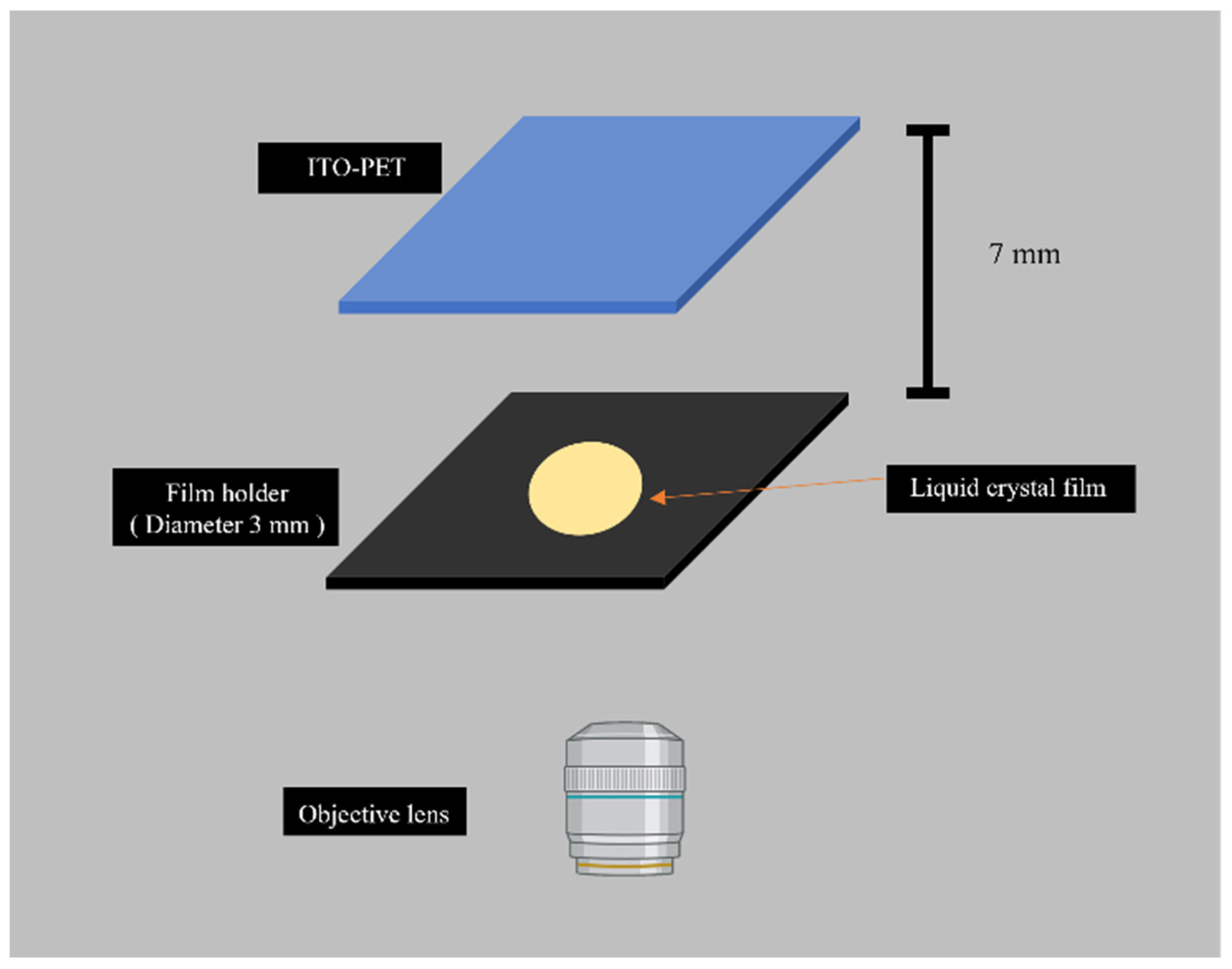
In this research, MX12805 (Miyota Development Center of America, MDCA, Longmont, CO, USA) liquid–crystal was utilized as the film material. Its phase transition sequence is as follows: Iso–84.7 °C–N*–81.4 °C–SmA*–66.1 °C–SmC*. The experiments were conducted in a custom-built chamber designed to precisely control the ambient environment. This chamber (
Figure 1) was equipped with a film holder (measuring 22 × 22 mm with a thickness of 0.4 mm) that features a 3 mm diameter circular aperture at its centroid to define the liquid–crystal film area. An indium tin oxide-polyethylene terephthalate (ITO-PET) substrate was positioned above the film holder, serving as the primary heat source for inducing thermal perturbations. All observations were performed using a polarizing microscope.
Film thickness was measured by analyzing the color of reflected light from thin liquid–crystal films. This method leverages the unique optical properties of birefringent thin films, where variations in thickness lead to distinct interference colors upon reflection [
7]. A microscope equipped with an LED light source and a camera was used to separate reflected light into its RGB components. The intensity of each color component was measured and normalized to obtain normalized color coordinates [
8]. This normalization, coupled with a calibration process using a mirror, effectively accounts for the microscope’s illumination spectrum and camera’s filter characteristics, allowing the normalized color coordinates to directly represent the film’s reflectivity. The theoretical basis for this measurement was Fresnel’s equations and the concept of extra optical phase retardation, which describes how light interacts with and interferes within the thin film [
8]. For normal incidence, the film’s reflectivity (
R) was modeled by a simplified equation, derived from these principles. This equation, combined with the known refractive index of the liquid–crystal, was used to draw theoretical reflectivity curves as a function of film thickness for various wavelengths.
Film thickness was also measured by fitting the measured normalized color coordinates from the film to pre-computed theoretical curves. The point where the measured R B normalized coordinates align closely with the theoretical predictions represents the film’s thickness. While this method yields multiple possible thickness values, the most probable average film thickness was obtained by averaging the values. The accuracy was validated against laser interference methods [
8].
3. Results and Discussion
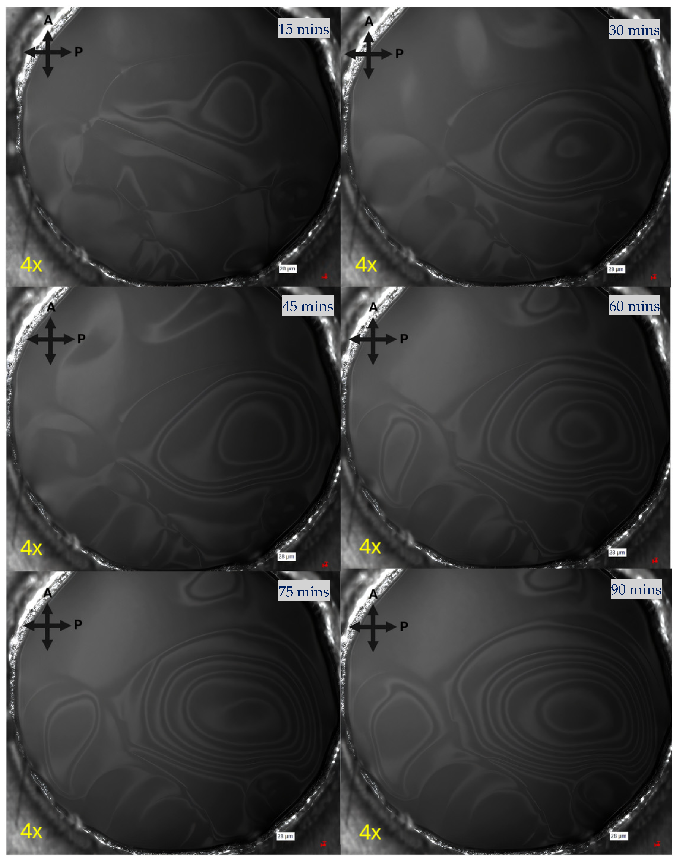
In fabricating the thin liquid–crystal film, we observed the formation and evolution of defects. Within the film’s area, special patterns, resembling concentric rings, originated in the area where the molecules were uniformly arranged. A point-like defect expanded as a ring pattern grew with the new point initiated in the middle of the ring, and the process was repeated as shown in
Figure 2.
Following the initial emergence of patterns in the well-aligned regions, molecular realignment progressed continuously. Adjacent molecules responded to this motion, resulting in the outward propagation of a spinning pattern. This collective rotational behavior generated dynamic patterns that were commonly observed within the system.
Figure 2 illustrates the temporal evolution of these patterns, captured using a reflected light polarizing microscope with crossed polarizers. The images depict the outward expansion of rotational patterns and their interaction with pre-existing defect lines. This consistent phenomenon, where patterns originate in ordered regions and propagate toward the boundary constraints, provides insight into molecular dynamics within thin films under thermal or external perturbations.
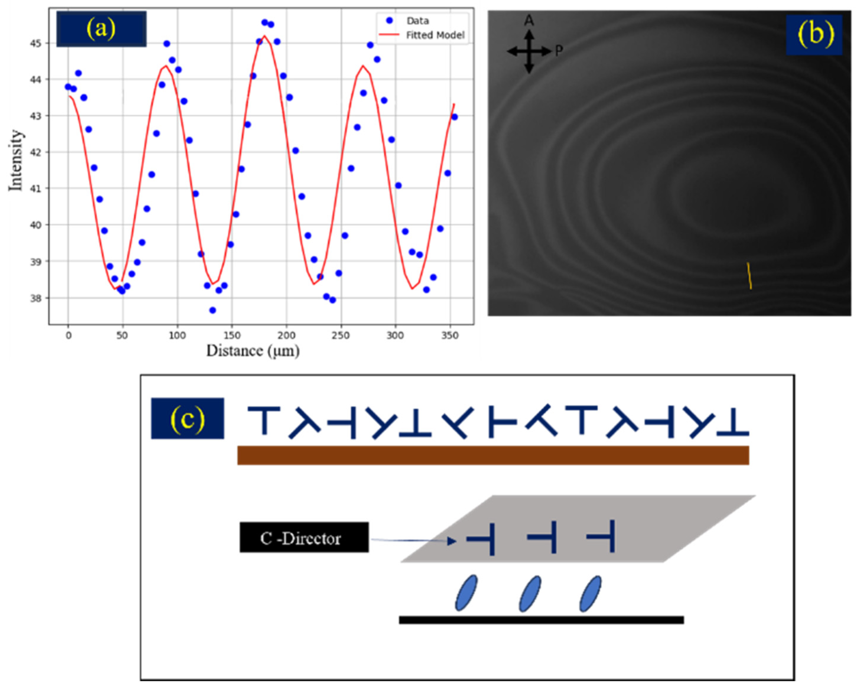
Furthermore, a detailed analysis of the observed line defect features revealed consistent characteristics as 2π wall defects [
9]. When comparing these identified defect patterns with the experimental intensity data, a strong correlation was observed. Specifically, the best-fit parameters for the theoretical intensity profile showed that the trend of the experimental intensity values aligned well with the calculated profile, as illustrated in
Figure 3. This agreement between the observed defect morphology and the theoretical prediction based on intensity measurements enables the understanding of the molecular configurations within these defect structures.
The optical properties of thin Smectic C liquid–crystal films are intrinsically associated with their anisotropic dielectric tensor, which is characterized by the director’s orientation, specifically its polar tilt angle (
θ) and azimuthal angle (
ϕ). The intensity of light reflected from such a film, particularly under specific polarization conditions, is described by a complex interplay of these angles and the film’s dielectric properties [
10].
In a special case, for normal incidence of light, this complex expression for reflected intensity can be simplified to a more direct relationship [
10]. This simplified form highlights the dependence of reflectivity on
δε,
,
and importantly, the fourth power of the sine of the polar tilt angle
and the square of the sine of twice the azimuthal angle
[
10].
While these theoretical models provide a rigorous physical description, for practical data analysis and the direct fitting of experimental observations, the full complexity can be simplified. A simplified fitting equation, commonly expressed to capture the functional dependence of the reflected intensity on the azimuthal angle
ϕ (particularly when observing the periodic rotation of the director) [
6].
where
,
, and
are empirical constants determined through the best-fit of Equation (2) to the experimental reflectivity data.
The fitted values of , , and were 24.312, 0.0292, and 0.8005, respectively. These values implicitly account for the influence of experimental conditions, the specific optical properties of the sample, and the fundamental physical constants embedded within more complex theoretical models. The simplified formulation enables direct and efficient extraction of the azimuthal angle (ϕ) from measured intensity data, exhibiting a periodic functional behavior analogous to that of the full theoretical expressions. This facilitates robust analysis of the director’s rotational dynamics.
The results demonstrate that the application of heat to a thin liquid–crystal film induces a temperature gradient, resulting in a corresponding heat flux. This heat flux drives the rotational motion of the liquid–crystal film and the evolution of associated defect patterns. The observed phenomenon is attributed to the thermally induced reorientation of liquid–crystal molecules, governed by thermomechanical torque, and is consistent with the defining characteristics of the Lehmann effect. Upon tracking the movement of line defects that are generated after heat application, these defects nucleated from the central region of the thin film’s affected area. The newly formed rings subsequently propagated outwards from their origin. As time progresses, additional line defects emerge and couple to multiple rings.
This phenomenon is attributed to the reorientation of liquid–crystal molecules, driven by the torque induced by the flow of heat flux. As this torque is generated, it propagates to surrounding molecules, causing the 2
-wall defect rings to move (
Figure 2). These changes in defect motion (
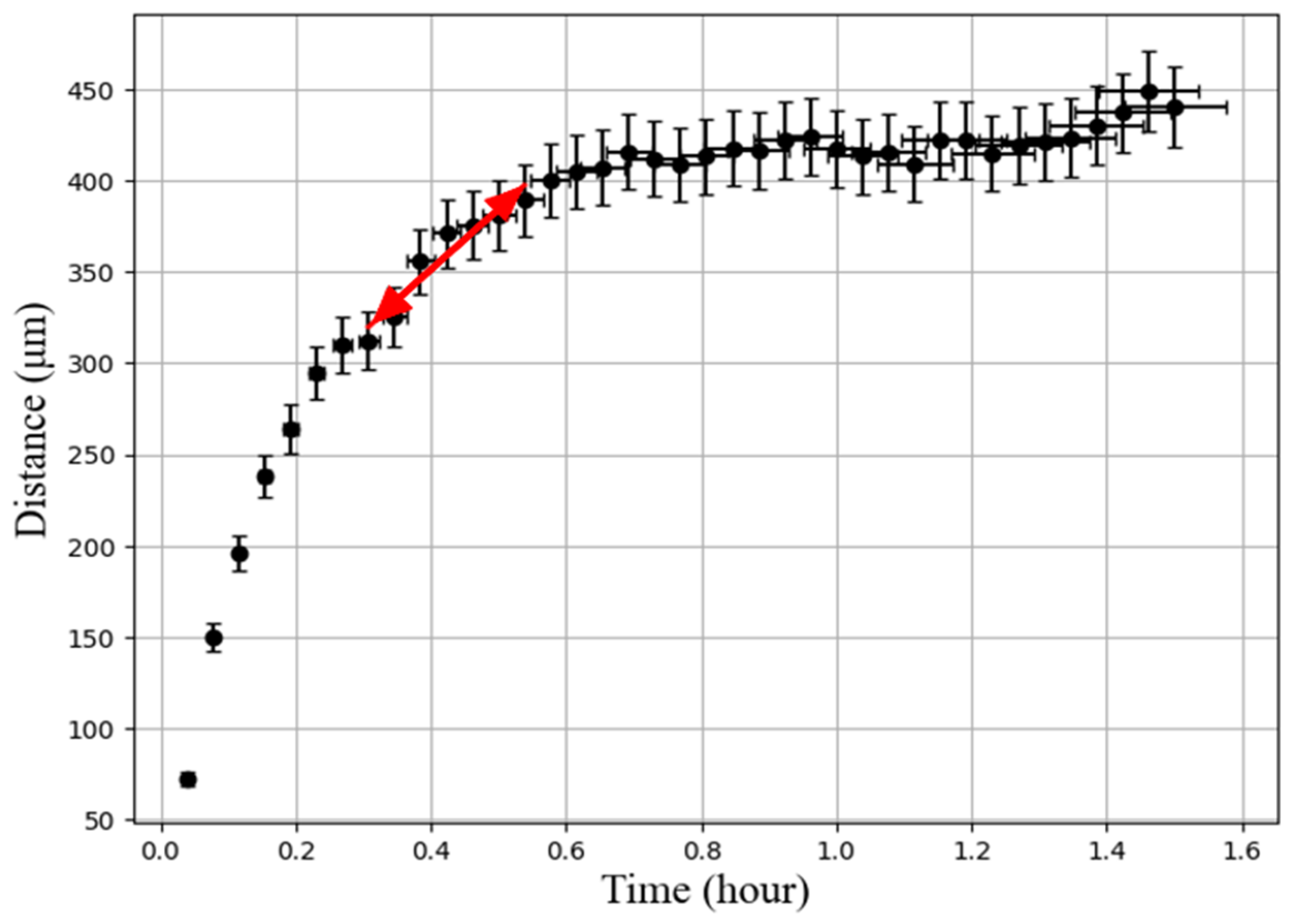
Figure 4) reveal that there is a considerable radial displacement when the temperature difference is significant. However, as time passes and the temperature difference diminishes while approaching equilibrium, the velocity of the defect movement notably decreases as the slope of the graph decreases (
Figure 4).
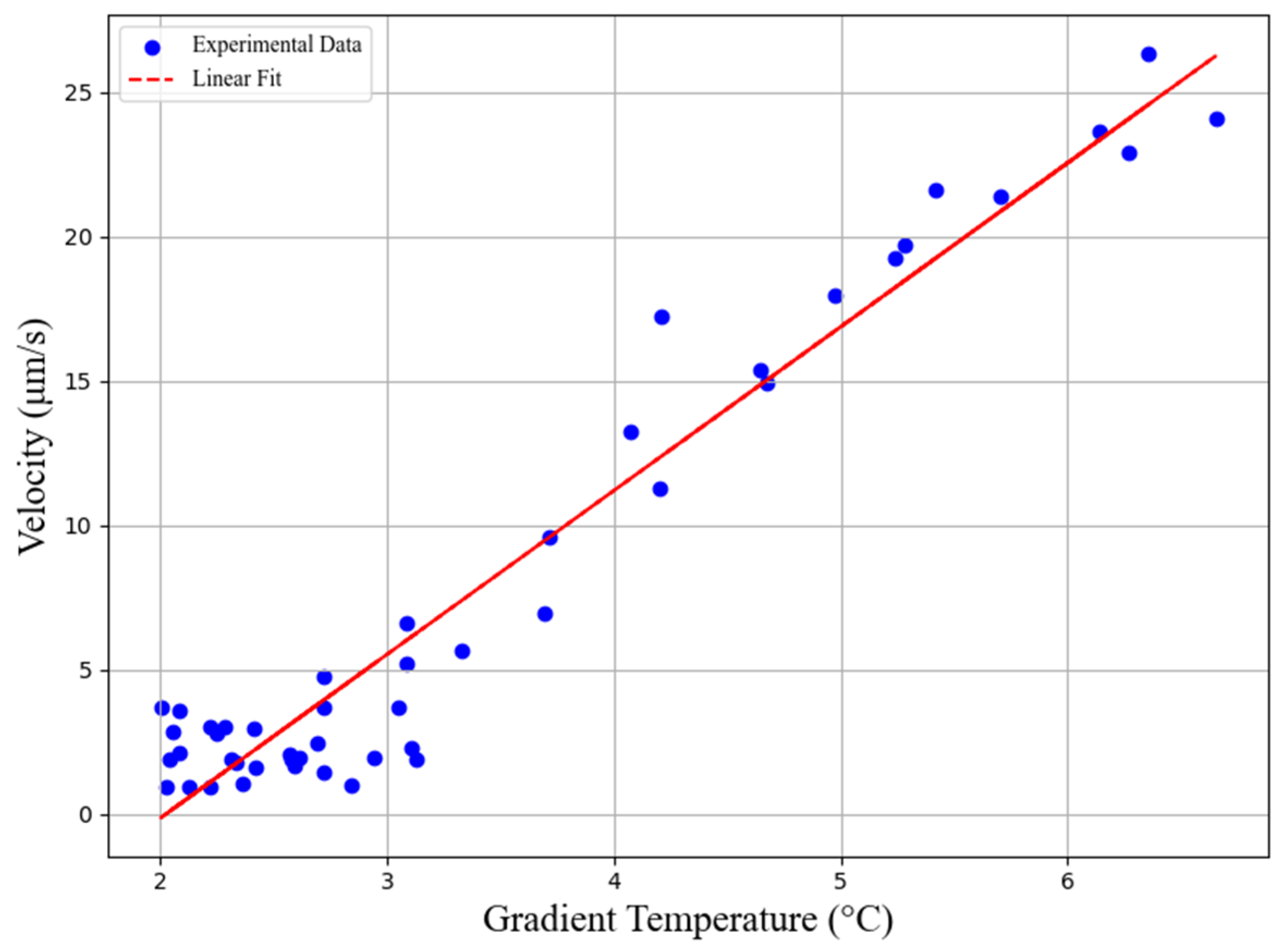
The gradient temperature ∆T was measured with the temperature sensors above and below the film at a distance of 1.5 mm.
Figure 5 shows the relationship between the velocity extracted from a red line in
Figure 4 for each ring defect moving radially outward and the applied ∆T. The linear relationship between the velocity and temperature difference is observed.



 ,
,