Proceeding Paper

An Effective Combination of PLC and Microcontrollers for Centralized Traffic Control and Monitoring System †

1
Department of Electrical Engineering, Minhaj University Lahore, Lahore 54770, Pakistan
2
Pakistan Meteorological Department, Lahore 54000, Pakistan
3
Department of Electrical Engineering, University of Management and Technology, Lahore 54770, Pakistan
*
Author to whom correspondence should be addressed.
Presented at the 1st International Conference on Energy, Power and Environment, Gujrat, Pakistan, 11–12 November 2021.
Eng. Proc. 2021, 12(1), 71; https://doi.org/10.3390/engproc2021012071
Published: 5 January 2022
(This article belongs to the Proceedings of The 1st International Conference on Energy, Power and Environment)

Abstract

:
In this paper, a smart and centralized traffic light control and monitoring system is proposed to control the modern transportation systems and make the city safer, using programmable logic controllers (PLCs) and programmable electronic microcontrollers. A camera is used to monitor the mishaps during the traffic flow of vehicles. The system has four modes, i.e., auto-control mode (ACM), manual control mode (MCM), central control mode (CCM), and remote control mode (RCM). In the auto-control mode (ACM), the traffic light signals are controlled automatically through programmable electronic microcontrollers at specific times, while the manual control mode (MCM) controls the traffic light signals manually (on–off switches) according to the traffic congestion. The central control mode (CCM) is considered to be a centralized mode, where the programmable logic controller (PLC) is used by a computer workstation. In this mode, the traffic light signals are controlled by a ladder logic program of the PLC. The third mode, RCM, is linked with the second mode, CCM; in this mode, the traffic light signals are remotely controlled through the software by transferring programmable logic controller (PLC) functions to the software interface. As a result, this transportation system can also be controlled remotely. The designed system delivers suitable, flexible, and reliable control for traffic signaling and transportation.

1. Introduction

In today’s era, controlling traffic is always an issue in highly populated countries; in some countries, a traffic warden system has been established, while others follow the automatic light controlling system. In this modern world, a smart transportation system is required to effectively control traffic light signals [1,2].
Many electromechanical processes, such as assembly lines in factories, amusement rides in theme parks, and light fixtures in facilities, are controlled by a PLC, where the PLC performs as a digital device used for automation [3]. The PLC can route many machines easily; this defines the flexibility area of the PLC. Some time ago, different controllers were required for each different electronic machine [4]. The microcontroller also played an effective role in designing the traffic control system. It is a compact device, or a tiny computer, based on an electronic chip that has a CPU, RAM, ROM, timers, and I/O ports. The system should also be scalable for incorporating new gadgets into it [5]. The reduction in energy utilization is a vital concern when designing a traffic control and monitoring system, and saving costs for underdeveloped countries [6,7,8,9].

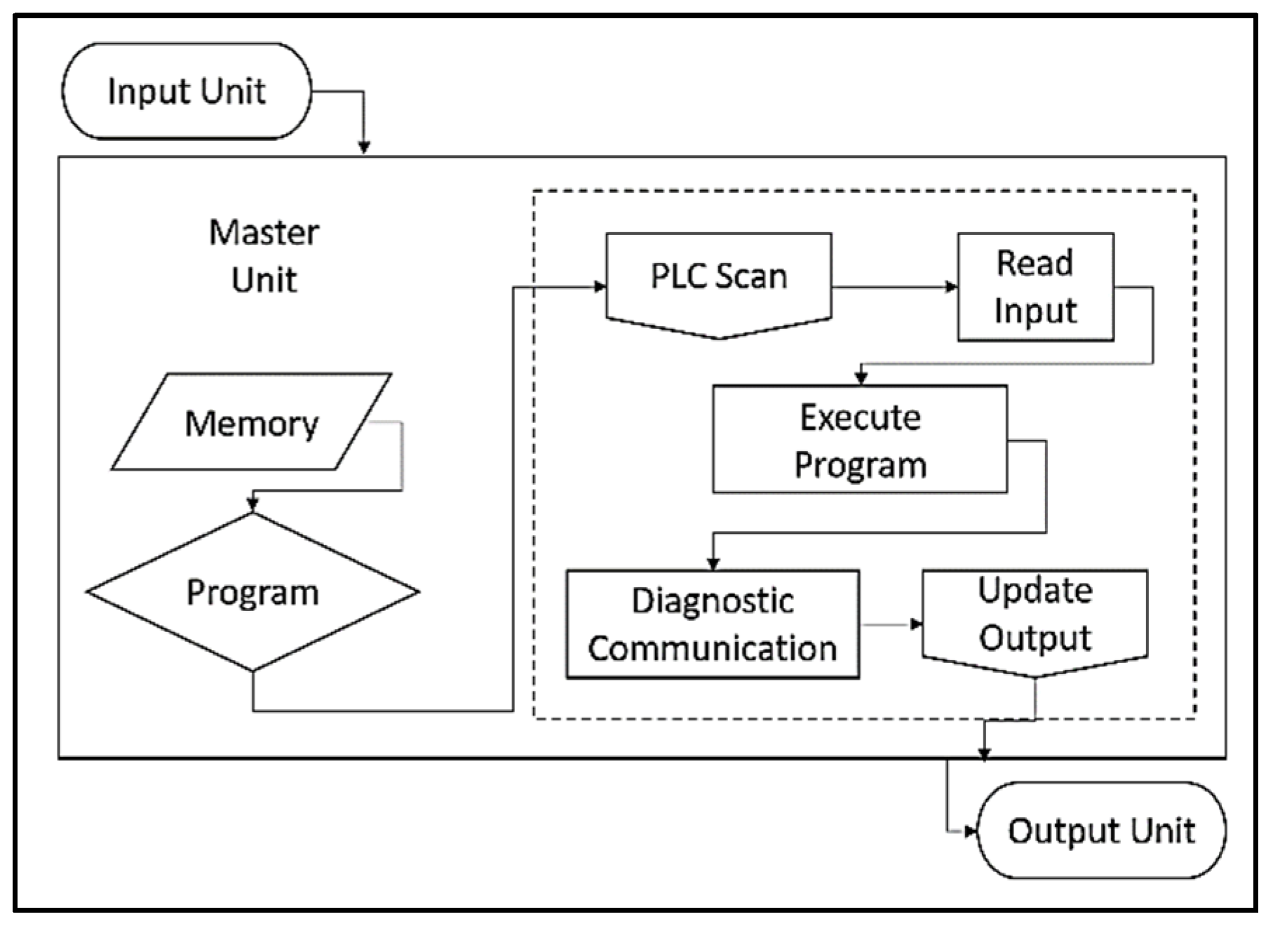
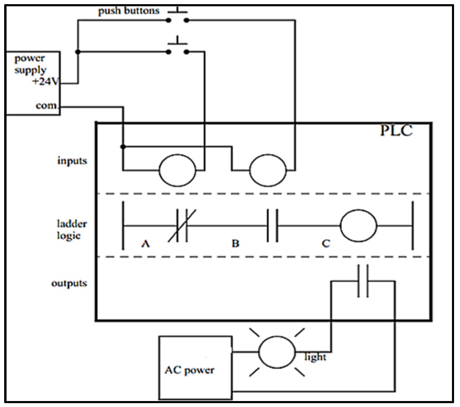
1.1. Internal Structure of PLC

Figure 1 indicates the internal structure of the PLC. The code/program is gathered into the memory of the PLC. The PLC memory picks up the code and initiates the process of scanning. During scanning, the PLC continuously reads the input side. If something happens on the input side, the PLC compiles the codes according to the input behavior. In the meantime, the PLC communicates with the output unit and varies the states according to the code.

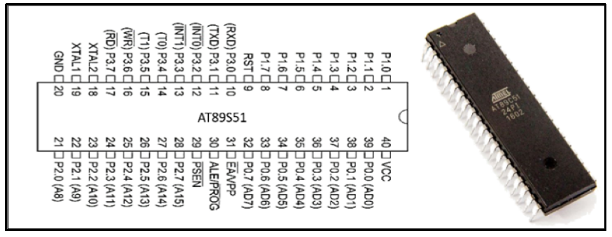
1.2. Internal Configuration of Microcontroller

Figure 2 describes the internal behavior of the Atmel AT89S51 microcontroller, which consists of 40 pins and 4 ports, i.e., P1, P2, P3, and P4. All the ports are bi-directional, except P0.

2. Research Flow Diagram

In Figure 3, the research is carried out from the first step, which is the selection of the PLC and microcontrollers. In implementation, a FATEK PLC is used, which is a 40 I/O modulated relay-type PLC. Four Atmel 89S51 microcontrollers are used in the implemented model, which is an 8-bit microcontroller. For surveillance, a simple AV Cam is used, and LED lights are used for traffic signaling. A seven-segment display is used as the traffic timer.

3. Methodology

PLC is considered as revolutionary in the automation field. Errors and faults in the codes/programs of PLC can be changed with ease in a short amount of time, which makes PLC more accessible. PLC initializes its tasks very quickly due to quick response behavior and this property makes PLC more valuable where time is important. As compared to other electronic devices PLC requires much less time to start. PLC provides the feature of internal passwords for security. In relay panels, programs can be changed easily by anyone whereas the PLC codes/programs are difficult to access by any other person.

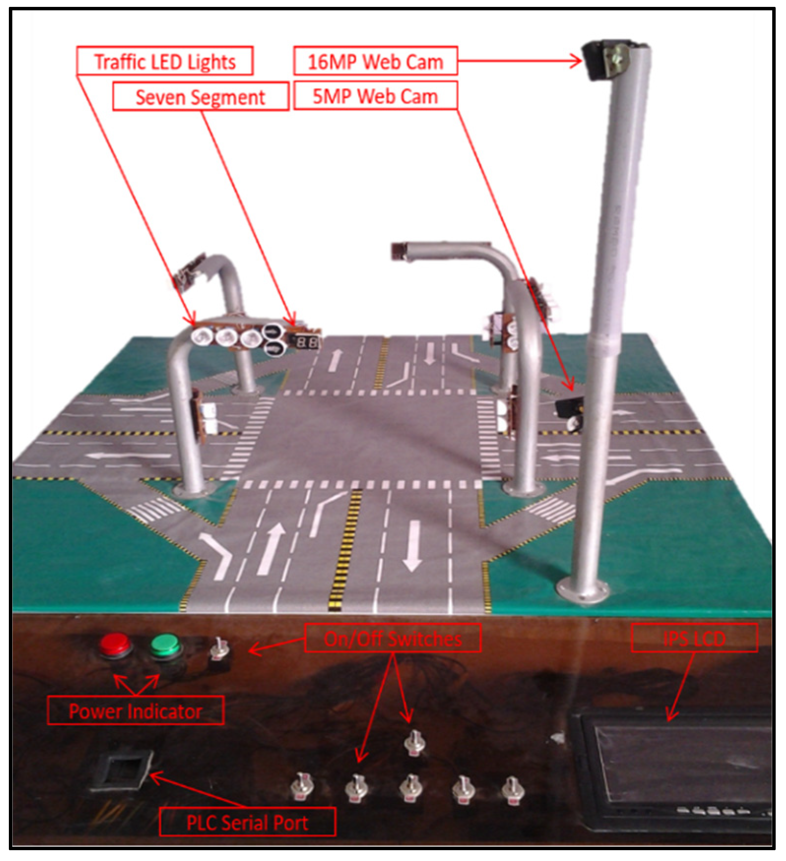
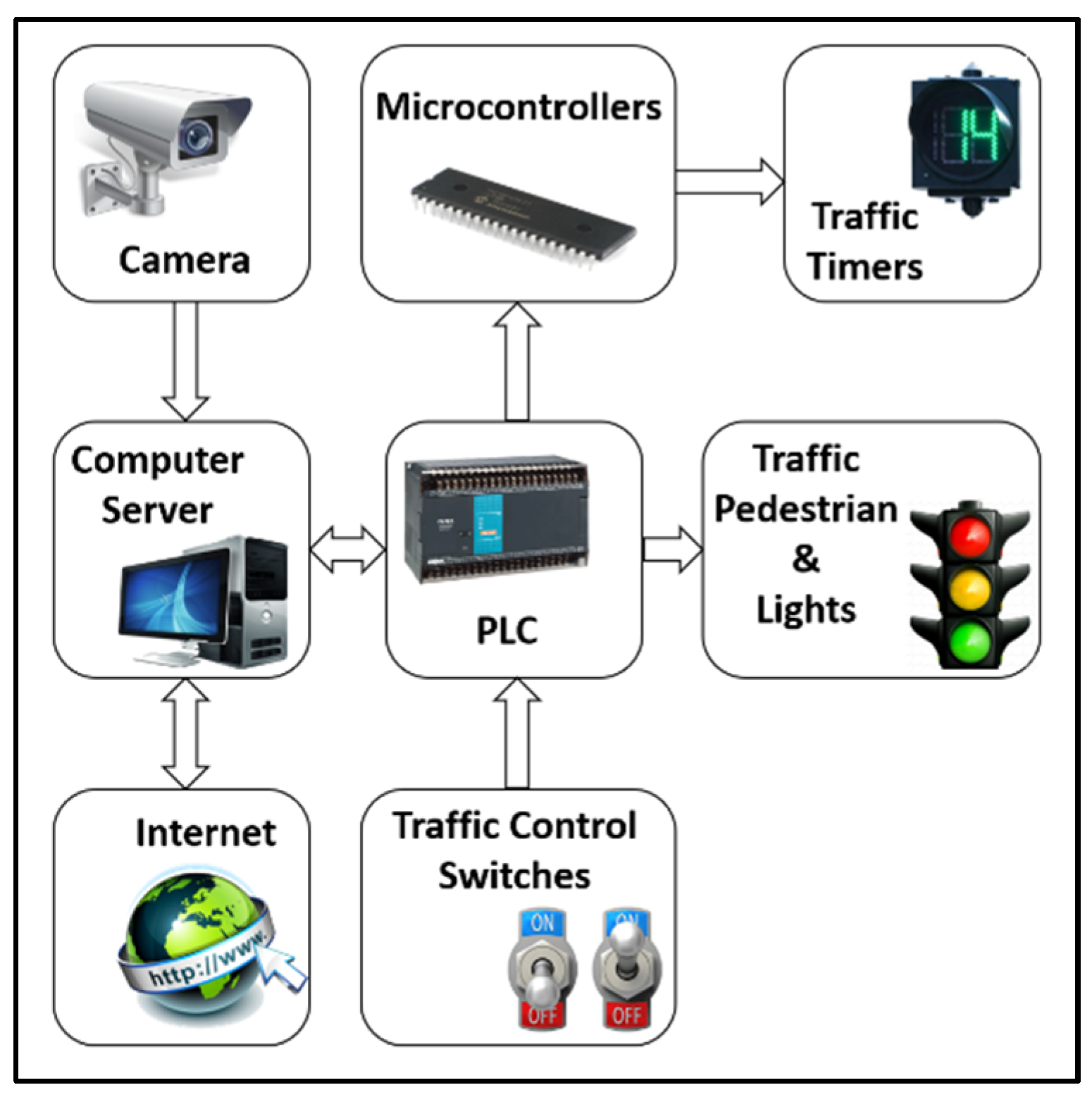
3.1. Implemented Model

PLC, microcontrollers and camera sensors are used to monitor the system and control traffic lights as shown in Figure 4. By default, the auto-control mode is enabled for controlling traffic light signals. Manual mode is activated by pushing the switch to manual, and as a result, light signals can be controlled according to traffic congestion. Using PLC software, traffic light signals can be controlled via central control station of the concerned area or city. This system can also be controlled remotely from anywhere in the world using TeamViewer software. Win ProLadder v3.11 and Keil µVision v3 are used to program PLC and microcontrollers, respectively.

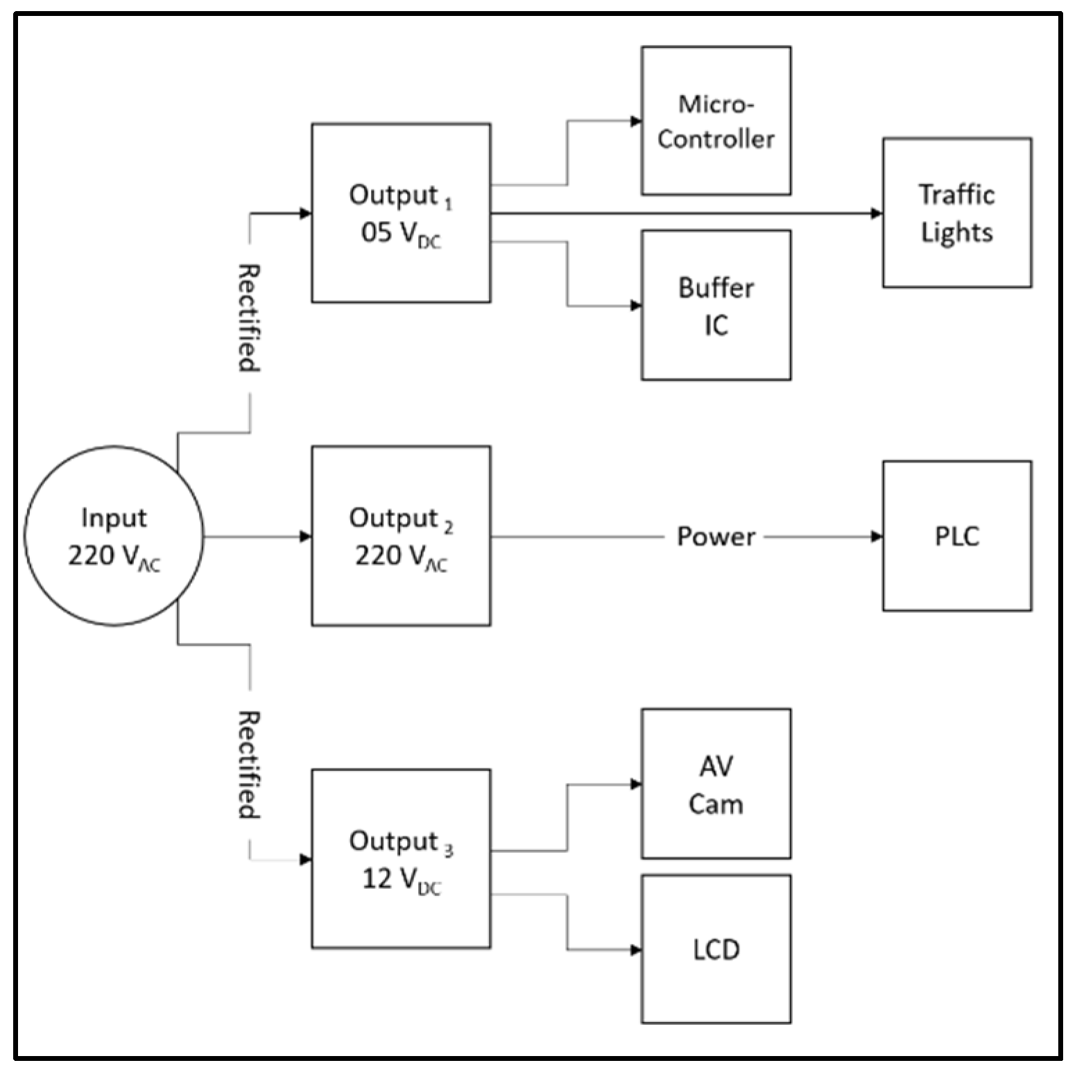
3.2. Power Division, Major Parts and Software

Figure 5 shows the power division of the implemented model. The 220 V AC voltage is converted to 5 V and 12 V DC voltages. The 5 V DC voltages are given to microcontrollers, buffer IC and traffic lights and the 12 V DC voltages are given to the AV camera and LCD to operate. Interlocking programming technique is used in PLC, which means one signal is operated at a time. Specifications of major and minor parts are shown in Table 1.

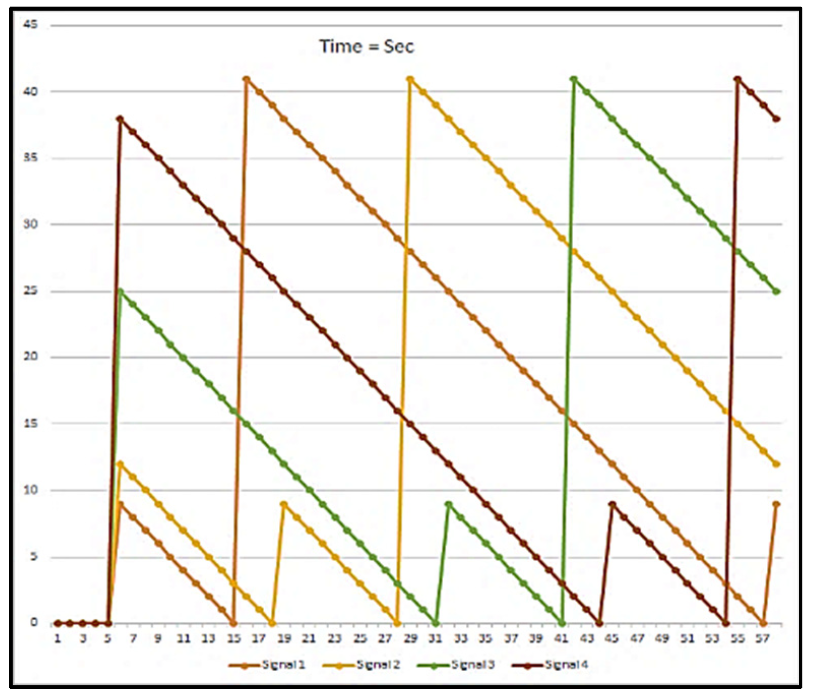
4. Results and Discussion

Ladder logic coding (LLC) is used to code the PLC, as shown in Figure 6, which indicates the complete framework of ladder logic coding (LLC). The inputs of the PLC are described as push button A and B, and these inputs are attached to the main input section. Logic 0 (L0) indicates that the push buttons are in an open state and logic 1 (L1) indicates that the push buttons are in a short state.
In ladder logic coding, push button A is normally represented as close contact and push button B is normally represented as open contact. The output is denoted as point C. A 220 V AC wire at the output section is interconnected to one point of the, normally open contact, push button B of the output (point C). The second terminal and neutral wire are directly joint with the lamp. The path of the ladder logic is completed when push button B is short. The seven-segment display and traffic light signals start working according to the PLC coding/program. All the sequences of the four traffic control lights are around fifty-two seconds, and one traffic control light sequence is around thirteen seconds. Figure 7 shows the graphic representation of the traffic timers.

5. Conclusions

From the above discussion, it is clear that the combination of PLC and microcontrollers in a traffic control system is much more effective and flexible than the other traditional traffic control systems. The PLC can work easily in frightful and critical circumstances, such as in dusty environments and hot weather. The PLC provides internal passwords for security. The PLC programs cannot be changed by any other person, and it is impenetrable to crack.

Author Contributions

Conceptualization, B.A. and Q.S.; methodology, B.A. and Q.S.; software, B.A.; formal analysis, Q.S.; investigation, B.A., Q.S and N.Z.; resources, Q.S. and H.M.T.; data curation, N.Z.; writing—original draft preparation, B.A.; writing—review and editing, B.A. and I.U.; visualization, B.A.; supervision, I.U.; project administration, B.A.; funding acquisition, B.A. and Q.S. All authors have read and agreed to the published version of the manuscript.

Funding

This research received no external funding.

Institutional Review Board Statement

Not Applicable.

Informed Consent Statement

Not Applicable.

Data Availability Statement

Not Applicable.

Conflicts of Interest

The authors declare no conflict of interest.

References

  1. Amir, S.; Kamal, M.S.; Khan, S.S.; Salam, K.M.A. PLC Based Traffic Control System with Emergency Vehicle Detection and Management. In Proceedings of the 2017 International Conference on Intelligent Computing, Instrumentation and Control Technologies ICICICT, Kannur, India, 6–7 July 2017; pp. 1467–1472. [Google Scholar] [CrossRef]
  2. Hanif, M.; Mohammad, N.; Harun, B. An Effective Combination of Microcontroller and PLC for Home Automation System. In Proceedings of the 2019 1st International Conference on Advances in Science, Engineering and Robotics Technology ICASERT, Dhaka, Bangladesh, 3–5 May 2019; pp. 1–6. [Google Scholar] [CrossRef]
  3. Technology Transfer. Available online: https://www.techtransfer.com/blog/programmable-logic-controller/ (accessed on 19 September 2021).
  4. Alzubaydy, A.I.J.; Aziz, A.B. Automatic Control of Electrical overhead Smart Trolley Crane AEOSTC Based Programmable Logic Controller (PLC). AJER 2017, 6, 54–62. Available online: http://www.ajer.org/papers/v6(12)/J06125462.pdf (accessed on 20 September 2021).
  5. Piyare, R.; Tazil, M. Bluetooth based home automation system using cell phone. In Proceedings of the 2011 IEEE 15th International Symposium on Consumer Electronics ISCE, Singapore, 13–16 June 2011; pp. 192–195. [Google Scholar] [CrossRef]
  6. Moser, K.; Harder, J.; Koo, S.G.M. Internet of things in home automation and energy efficient smart home technologies. In Proceedings of the 2014 IEEE International Conference on Systems, Man, and Cybernetics SMC, San Diego, CA, USA, 5–8 October 2014; pp. 1260–1265. [Google Scholar] [CrossRef]
  7. Ullah, I.; Ullah, F.; Ullah, Q.; Shin, S. Integrated Tracking and Accident Avoidance System for Mobile Robot. Int. J. Control Autom. Syst. 2013, 11, 1253–1265. [Google Scholar] [CrossRef]
  8. Ullah, I.; Ullah, F.; Ullah, Q. A sensor based robotic model for vehicle collision reduction. In Proceedings of the International Conference on Computer Networks and Information Technology, Abbottabad, Pakistan, 11–13 July 2011; pp. 251–255. [Google Scholar] [CrossRef]
  9. Ullah, I.; Ullah, Q.; Ullah, F.; Shin, S. Integrated collision avoidance and tracking system for mobile robot. In Proceedings of the 2012 International Conference of Robotics and Artificial Intelligence, Rawalpindi, Pakistan, 22–23 October 2012; pp. 68–74. [Google Scholar] [CrossRef]
Figure 1. Internal block diagram of PLC.
Engproc 12 00071 g001
Figure 2. AT89S51 PIN configuration.
Engproc 12 00071 g002
Figure 3. Research flow diagram.
Engproc 12 00071 g003
Figure 4. Implemented model.
Engproc 12 00071 g004
Figure 5. Power division block diagram.
Engproc 12 00071 g005
Figure 6. Ladder Logic Diagram of PLC.
Engproc 12 00071 g006
Figure 7. Traffic Timers Response of Model.
Engproc 12 00071 g007
Table 1. Specification of PLC, microcontroller and other major/minor parts.
Major PartsMinor Parts
PLC:
FATEK FBs-40-MAR-AC,
Master-Unit, Relay-Type,
40 I/O = 24 I/P-16 O/P,
I/P Volts = 220 VAC,
Built-in Power Supply
Microcontroller:
Atmel AT89S51 (40 Pins),
ROM/RAM = 4 KB/128 bytes,
I/P Pins = 32,
Timer/Counter = 2(16 Bit),
Interrupts = 6, Vcc = 5 V
Power Supply:
I/P = 220 VAC,
O/P = 5 & 12 VDC
IPS LCD: 12 VDC
AV Cameras: 5MP & 16MP
Buffer IC: 74LS245-5VDC
Clock Crystal: 12 MHz
Capacitor: 10 µF
Resistances: 120 Ω, 8.2 kΩ
Power Indicator Light: 220 VAC
Seven Segment: Common Cathode
LED Lights: Red, Green & Yellow
Publisher’s Note: MDPI stays neutral with regard to jurisdictional claims in published maps and institutional affiliations.

