Proceeding Paper

A Comparative Analysis of Half-Bridge LLC Resonant Converters Using Si and SiC MOSFETs †

1
Department Electrical Power Engineering, U.S.-Pakistan Center for Advanced Studies in Energy (USPCAS-E), National University of Sciences and Technology, Sector H-12, Islamabad 44000, Pakistan
2
Department Electrical Engineering, SARHAD University of Science and Information Technology, Peshawar 25000, Pakistan
*
Author to whom correspondence should be addressed.
Presented at the 1st International Conference on Energy, Power and Environment, Gujrat, Pakistan, 11–12 November 2021.
Eng. Proc. 2021, 12(1), 43; https://doi.org/10.3390/engproc2021012043
Published: 28 December 2021
(This article belongs to the Proceedings of The 1st International Conference on Energy, Power and Environment)

Abstract

:
With the expansion of renewable energy sources worldwide, the need for developing more economical and more efficient converters that can operate on a high frequency with minimal switching and conduction losses has been increased. In power electronic converters, achieving high efficiency is one of the most challenging targets to achieve. The utilization of wideband switches can achieve this goal but add additional cost to the system. LLC resonant converters are widely used in different applications of renewable energy systems, i.e., PV, wind, hydro and geothermal, etc. This type of converter has more benefits than the other converters such as high electrical isolation, high power density, low EMI, and high efficiency. In this paper, a comparison between silicon carbide (SiC) MOSFET and silicon (Si) MOSFET switches was made, by considering a 3KW half-bridge LLC converter with a wide range of input voltage. The switching losses and conduction losses were analyzed through mathematical calculations, and their authenticity was validated with the help of software simulations in PSIM. The results show that silicon carbide (SiC) MOSFETs can work more efficiently, as compared with silicon (Si) MOSFETs in high-frequency power applications. However, in low-voltage and low-power applications, Si MOSFETs are still preferable due to their low-cost advantage.

1. Introduction

DC–DC converters play vital roles in various applications such as microgrids, electrical vehicles, fast battery charging systems, etc. Efficiency is a key factor in the selection and designing of converters. A mostly commercially available converter is based on silicon devices. Theoretically, silicon (Si)-based switches have some limitations; in particular, their power density and efficiency cannot be improved up to some extent [1]. In the literature, different types of converter topologies have been introduced to minimize losses, which lead to an increase in the number of switches and the overall complexity of the system [2]. The wide bandgap-switching devices such as silicon carbide (SiC) switches can perform more efficiently in high-frequency, high-power-density, and high-voltage applications, as compared with Si switches [3].
Based on switching techniques, converters are classified into two types, i.e., hard switching and soft switching. Hard-switching converters (e.g., buck converter, boost converters, etc.) have less efficiency in high switching frequency due to high switching losses [4]. However, resonant converters are based on the soft-switching technique, which allows the operation at maximum switching frequency with low switching losses [5]. In the literature, various topologies of resonant converters have been presented for various applications of which LLC converters are most popular [6]. A half-bridge LLC-based resonant converter allows switches to operate in a wide power range with zero voltage switching (ZVS) and zero current switching (ZCS) [7,8].
In this paper, a half-bridge LLC resonant converter with silicon (Si) MOSFET was compared with a model having a silicon MOSFET. Simulation software PSIM was used for simulation and calculation of conduction losses and switching losses. Both models were compared on a wide range of input voltage. Conduction losses and switching losses were calculated under different loads.

2. LLC Resonant Converter

The topology proposed is “half-bridge LLC resonant converter”, which is shown in Figure 1. Parameters of designed HB LLC resonant converter is shown in Table 1. This type of converter consists of two switches. Each switch works in half cycle, with a duty cycle of 0.5. The proposed circuit consists of a resonant circuit that contains an inductor, capacitor, and high-frequency transformer.
In this paper, a 3 KW half-bridge LLC resonant converter was modeled for silicon carbide (SiC) MOSFET (SCT3080KL) and silicon (Si) MOSFET (STW45NM50) to analyze their performance. The converter was designed using and controlled using the frequency modulation technique. In the frequency modulation technique, the output voltage is controlled by changing frequency.

3. Mathematical Modeling

Calculation of losses across MOSFET in half-bridge LLC resonant converter.
Conduction losses across one MOSFET are determined as follows:
P c o n d = I r m s 2 R d D u t y   c y c l e  
Switching losses across one MOSFET are calculated as follows:
P s w = ( V i n 2 ) I p e a k   t o f f f s w  
Total losses in all the MOSFETS will thus be,
P t o t a l = 2 ( P c o n d + P s w )  
where the silicon SiC MOSFET–SCT3080KL was used in one model, while Si MOSFET–STW45NM50 was used in the other model. Table 2 shows the summarized mathematical results of both models.

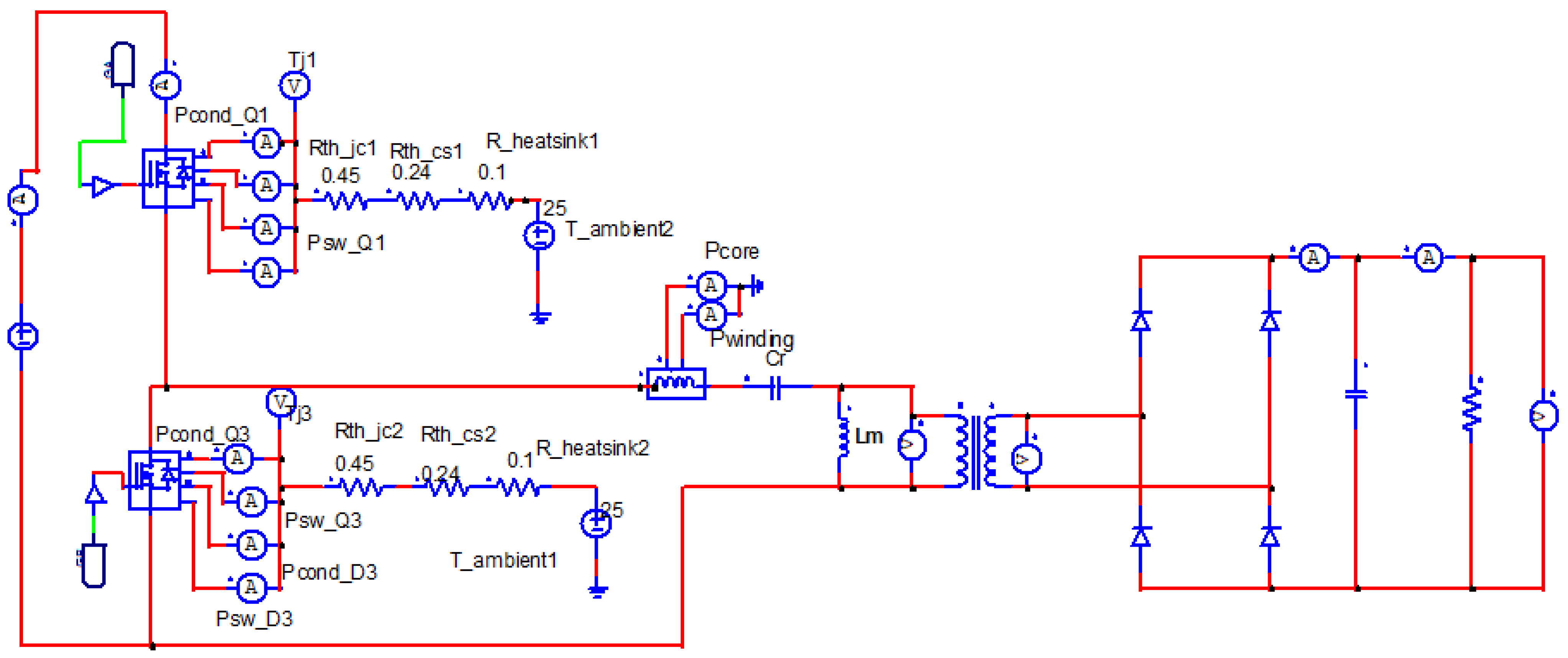
4. Simulations and Results

Figure 2a shows the efficiency analysis of silicon and silicon (Si) carbide (SiC) switches for different loads. Analysis shows that at load 25%, the load efficiency of the converter with silicon MOSFET is much lower than converter with SiC MOSFETs. Figure 2b shows efficiency analysis for change in input voltage. At nominal voltage, efficiency is maximum. As voltage increases from nominal voltage, efficiency decreases.
Loss comparisons of SiC and SiC at full and half load are shown in Figure 3a,b, which shows that switching losses and conduction losses in SiC MOSFETs are less than Si MOSFETs. Silicon carbide (SiC) MOSFET works more efficiently than silicon (Si) MOSFET.
Figure 4a,b show switching and conduction losses of Silicon and Silicon Carbide MOSFETs at different input voltages, respectively. Results show that switching losses increases with an increase in input Voltage. At low voltage Conduction loss is maximum. Results show that switching losses of Silicon Carbide SiC MOSFETs is much lower than Silicon MOSFETs.

5. Conclusions

In this paper, a half-bridge LLC converter was designed for silicon (STW45NM50) and silicon carbide (SCT3080KL) MOSFETs. Properties of silicon and silicon carbide were compared for the 3 kW half-bridge LLC resonant converter. Switching losses and conduction losses were simulated in PSIM. Results were compared for a wide range of input voltage, switching frequency, and power. The results show that silicon carbide (SiC) MOSFET can work more efficiently, as compared with Silicon (Si) MOSFETs, in high-frequency power applications. However, in low-voltage and low-power applications, Si MOSFETs are still preferable due to their low-cost advantage.

Conflicts of Interest

The authors declare no conflict of interest.

References

  1. Lin, B.R. Analysis of a Series-Parallel Resonant Converter for DC Microgrid Applications. Processes 2021, 9, 542. [Google Scholar] [CrossRef]
  2. Pandey, P.; Agnihotri, P. An Efficient LLC Resonant Converter Design for Photovoltaic Application. In Proceedings of the 2019 8th International Conference on Power Systems (ICPS), Jaipur, India, 20–22 December 2019; pp. 1–6. [Google Scholar] [CrossRef]
  3. Aghdam, M.G.H.; Thiringer, T. Comparison of SiC and Si power semiconductor devices to be used in 2.5 kW DC/DC converter. In Proceedings of the 2009 International Conference on Power Electronics and Drive Systems (PEDS), Taipei, Taiwan, 2–5 November 2009; pp. 1035–1040. [Google Scholar] [CrossRef]
  4. van den Bossche, A.; Stoyanov, R.; Dukov, N.; Valchev, V.; Marinov, A. Analytical simulation and experimental comparison of the losses in resonant DC/DC converter with Si and SiC switches. In Proceedings of the 2016 IEEE International Power Electronics and Motion Control Conference (PEMC), Varna, Bulgaria, 18–23 September 2016; pp. 934–939. [Google Scholar] [CrossRef]
  5. Zhao, T.; Wang, J.; Huang, A.Q.; Agarwal, A. Comparisons of SiC MOSFET and Si IGBT Based Motor Drive Systems. In Proceedings of the 2007 IEEE Industry Applications Annual Meeting, New Orleans, LA, USA, 23–27 September 2007; pp. 331–335. [Google Scholar] [CrossRef]
  6. Steigerwald, R.L. A comparison of half-bridge resonant converter topologies. IEEE Trans. Power Electron. 1988, 3, 174–182. [Google Scholar] [CrossRef]
  7. Jiang, T.; Lin, Q.; Zhang, J.; Wang, Y. A novel ZVS and ZCS three-port LLC resonant converter for renewable energy systems. In Proceedings of the 2014 IEEE Energy Conversion Congress and Exposition (ECCE), Pittsburgh, PA, USA, 14–18 September 2014; pp. 2296–2302. [Google Scholar] [CrossRef]
  8. Gopiyani, A.; Patel, V.; Shah, M.T. A novel half-bridge LLC Resonant Converter for high power DC power supply. In Proceedings of the 2010 Conference Proceedings IPEC, Singapore, 27–29 October 2010; pp. 34–39. [Google Scholar] [CrossRef]
Figure 1. PSIM simulation model of half-bridge LLC resonant converter.
Engproc 12 00043 g001
Figure 2. (a) Analysis of efficiency for change in input voltages; (b) analysis of efficiency for change of load.
Engproc 12 00043 g002
Figure 3. (a) Loss comparison of SiC and Si at full load; (b) loss comparison of SiC and Si at 50% load.
Engproc 12 00043 g003
Figure 4. (a) Loss analysis of Si MOSFETs for input voltages [V]; (b) loss analysis of SiC MOSFETs for input voltages [V].
Engproc 12 00043 g004
Table 1. Specification of HB LLC resonant converter.
ParameterValueUnit
Power P o u t 3 k W
Output Voltage V o u t 400 V
Input Voltage V i n 300 V
Switching Frequency f s w 100 k H z
Resonant Capacitor C r 233 n F
Magnetizing Inductance L m 38.03 u H
Resonant Inductance L r 10.07 u H
Table 2. Loss comparison of SiC and Si MOSFETs.
ModelSCT3080KLSTW45NM50
I r m s 22.222.2
I p e a k 28.2828.28
P c o n d [W]19.719.7
P s w [W]5.09045.3117
P t o t a l [W]49.580850.22
Publisher’s Note: MDPI stays neutral with regard to jurisdictional claims in published maps and institutional affiliations.

