
Improving the Stability of Islanded DC Microgrid with Constant Power Loads †

 , , and
Abstract
:1. Introduction
2. Methodology
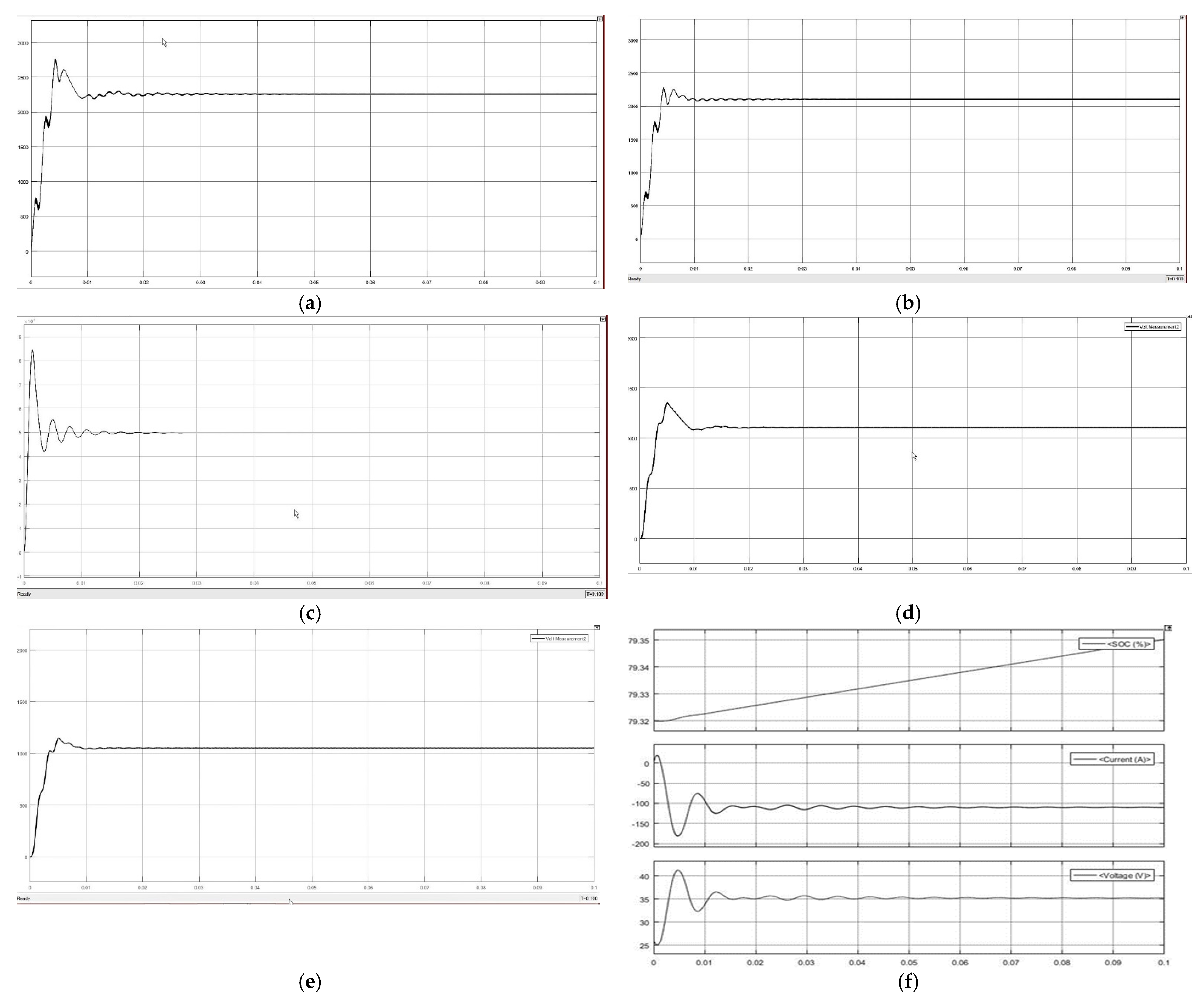
3. Results
4. Conclusions
Conflicts of Interest
References
- Chen, F. Control of DC Power Distribution Systems and Low-Voltage Grid-Interface Converter Design. Ph.D. Dissertation, Virginia Tech, Blacksburg, VA, USA, 2017. Available online: https://vtechworks.lib.vt.edu (accessed on 22 September 2021).
- Elsayed, A.T.; Mohamed, A.A.; Mohammed, O.A. DC microgrids and distribution systems: An overview. Electr. Power Syst. Res. 2015, 119, 407–417. [Google Scholar] [CrossRef]
- World Corbon Dioxide Emission from Fossil Fuel Combustion and Globel Atmosphere Concetrations. Available online: https://bit.ly/2WaLi0n (accessed on 22 September 2021).
- Voltage Disturbances Standard EN 50160, Voltage Characteristics in Public Distribution Systems. Available online: https://copperalliance.org.uk/uploads/2018/03/542-standard-en-50160-voltage-characteristics-in.pdf (accessed on 17 December 2021).
- Average Annual Growth Rates of World Renewables Supply, 1990–2018–Charts–Data & Statistics-IEA. Available online: https://bit.ly/3o3U1Nj (accessed on 19 January 2021).
- Devices, S. Stability Analysis of DC Distribution Systems with Droop-Based Charge Sharing on Energy Storage Devices. Energies 2017, 10, 433. [Google Scholar] [CrossRef] [Green Version]
- Anand, S.; Fernandes, B.G. Reduced Order Model and Stability Analysis of Low Voltage DC Microgrid. IEEE Trans. Ind. Electron. 2012, 60, 5040–5049. [Google Scholar] [CrossRef]
- Bharath, K.R.; Mithun, M.K.; Kanakasabapathy, P. A Review on DC Microgrid Control Techniques, Applications and Trends. Int. J. Renew. Energy Res. 2019, 9, 1328–1338. [Google Scholar]
- Shivam; Dahiya, R. Intelligent Distributed Control Techniques for Effective Current Sharing and Voltage Regulation in DC Distributed Systems. Arab. J. Sci. Eng. 2017, 42, 5071–5081. [Google Scholar] [CrossRef]
- Li, F.; Member, S.; Lin, Z.; Member, S.; Qian, Z.; Wu, J. A Dual-Window DC Bus Interacting Method for DC Microgrids Hierarchical Control Scheme. IEEE Trans. Sustain. Energy 2019, 11, 652–661. [Google Scholar] [CrossRef] [Green Version]
- Lee, G.; Member, S.; Ko, B.; Member, S. A Distributed Control Method Based on a Voltage Sensitivity Matrix in DC Microgrids with Low-Speed Communication. IEEE Trans. Smart Grid 2018, 3053, 1–9. [Google Scholar] [CrossRef]
- Gao, L.; Liu, Y.; Ren, H.; Guerrero, J.M. A DC Microgrid Coordinated Control Strategy Based on Integrator Current-Sharing. Energies 2017, 10, 1116. [Google Scholar] [CrossRef] [Green Version]


| Parameters | Buck Converter | Boost Converter |
|---|---|---|
| Vin | 100 V | 100 V |
| Diode Resistance on | 0.001 | 0.001 |
| Period | 1/25,000 | 1/25,000 |
| Pulse Width | 50% | 75% |
| Inductance | 1000 | 3.3 × 10⁻⁵ |
| Capacitance | 4.3 × 10⁻⁴ | 3.3 × 10⁻² |
Publisher’s Note: MDPI stays neutral with regard to jurisdictional claims in published maps and institutional affiliations. |
© 2022 by the authors. Licensee MDPI, Basel, Switzerland. This article is an open access article distributed under the terms and conditions of the Creative Commons Attribution (CC BY) license (https://creativecommons.org/licenses/by/4.0/).
Share and Cite
Murtaza, S.A.; Siddique, N.; Aslam, J.; Latif, W.; Wasif, M.; Hussain, I. Improving the Stability of Islanded DC Microgrid with Constant Power Loads. Eng. Proc. 2021, 12, 11. https://doi.org/10.3390/engproc2021012011
Murtaza SA, Siddique N, Aslam J, Latif W, Wasif M, Hussain I. Improving the Stability of Islanded DC Microgrid with Constant Power Loads. Engineering Proceedings. 2021; 12(1):11. https://doi.org/10.3390/engproc2021012011
Chicago/Turabian StyleMurtaza, Sajid Ali, Nazam Siddique, Javaid Aslam, Waqas Latif, Muhammad Wasif, and Iftikhar Hussain. 2021. "Improving the Stability of Islanded DC Microgrid with Constant Power Loads" Engineering Proceedings 12, no. 1: 11. https://doi.org/10.3390/engproc2021012011
APA StyleMurtaza, S. A., Siddique, N., Aslam, J., Latif, W., Wasif, M., & Hussain, I. (2021). Improving the Stability of Islanded DC Microgrid with Constant Power Loads. Engineering Proceedings, 12(1), 11. https://doi.org/10.3390/engproc2021012011