Proceeding Paper

Bilateral Teleoperation of a Formation of Mobile Robot Using Proportional Control and Obstacle Avoidance: Experimental Results †

1
Departamento de Automatización y Control Industrial, Facultad de Ingeniería Eléctrica y Electrónica, Escuela Politécnica Nacional, Quito 170525, Ecuador
2
Colegio de Ciencias e Ingeniería, Universidad San Francisco de Quito, Quito 170901, Ecuador
*
Author to whom correspondence should be addressed.
Presented at the XXXIII Conference on Electrical and Electronic Engineering, Quito, Ecuador, 11–14 November 2025.
Eng. Proc. 2025, 115(1), 10; https://doi.org/10.3390/engproc2025115010
Published: 15 November 2025
(This article belongs to the Proceedings of The XXXIII Conference on Electrical and Electronic Engineering)

Abstract

This article proposes a distributed formation control strategy for mobile robots (using TurtleBot3 Burger platforms) based on teleoperation using artificial forces and mechanical impedance modeling. The proposed control law is structured in cascade, consisting of an external loop responsible for maintaining the formation and an internal loop dedicated to obstacle avoidance. Bilateral teleoperation is enabled by integrating the Novint Falcon haptic device, which allows the human operator to issue velocity commands to the formation and receive force feedback based on the robots’ physical interactions with congested environments. This strategy improves remote perception of the environment and promotes safe and collaborative navigation, validated through experiments in real-world environments.

1. Introduction

Bilateral teleoperation is considered fundamental in modern robotics, enabling the remote control of robotic systems with haptic feedback and facilitating intuitive human interaction with distant, unknown, or hazardous environments [1,2]. This technology is widely applied in robot-assisted surgery, space exploration, hazardous material handling, and precision industrial operations [3,4,5]. For instance, ref. [3] proposes a strategy based on neural networks to compensate for delays in the robotic system, improving the system’s adaptability. Likewise, the teleoperation of mobile robot formations has been gaining relevance in cooperative inspection, cooperative transport, and simultaneous exploration applications. In [6], a scheme based on improved potential fields and virtual robots is presented to avoid obstacles during formation. Complementarily, ref. [7] proposes event planning and hybrid force/position control, which served as the theoretical basis for the evolution of modern architectures. Meanwhile, ref. [8] implements adaptive control for trajectory tracking and posture control for a group of robots, which is related to our distributed control approach to maintain the desired formation. This approach is aligned with the principles described in [9], which presents a comprehensive analysis of formation control strategies in robotics, including hierarchical, distributed, and limited perception approaches.
Teleoperation has demonstrated effectiveness in simulation and remote operation, enabling human intervention [10]. The dynamic characterization of this device is presented in [4], and its integration with CHAI3D and MATLAB for interaction with the virtual humanoid robot iCub is shown in [5]. An SMC controller for mobile robot teleoperation in obstacle-rich environments was explored in [11], though without haptic feedback or cooperative formation. In contrast, ref. [12] proposed a position-based impedance control strategy for bilateral teleoperation ensures trajectory tracking and force feedback, validated experimentally with a Novint Falcon and a 7-DOF robot. In multi-robot cooperation, ref. [13] presented a hybrid architecture for cooperative object transport, and ref. [2] proposed a distributed dual-arm manipulator architecture for multimodal synchronization. Robust human–robot synchronization in interconnected systems was analyzed in [14], addressing stability in teleoperation. Furthermore, ref. [15] introduced consensus algorithms for bidirectional teleoperation of aerial manipulators in cluttered environments. This work presents a bilateral teleoperation system for a formation of three Turtlebot3 Burger robots, integrating a Novint Falcon haptic device (Novint Technologies, Albuquerque, USA) for force feedback during obstacle avoidance. A cascade control scheme combines a PID formation controller with a velocity-based obstacle avoidance controller using LiDAR (Light Detection and Ranging) data. Force feedback from each robot is transmitted to the operator through the Novint Falcon, representing virtual physical interactions with the environment and alerting to possible collisions, both external and between robots. Based on a review of the literature, the main contribution of this article is to demonstrate the experimental feasibility of integrating bilateral teleoperation with cooperative multi-robot formation and an active obstacle avoidance mechanism. Unlike previous studies, which focus on isolated aspects such as trajectory control [10], unilateral teleoperation [12], or coordination without haptic feedback [3], this proposal achieves a more immersive, safe, and efficient human–robot physical interaction. Furthermore, it explicitly considers the dynamics of the operator and the environment, integrating teleoperation as an active virtual force in velocity control. This article is organized as follows: Section 1 presents the introduction, Section 2 describes the modeling of mobile robots and multi-robot formation, Section 3 presents the formation and obstacle avoidance controllers, Section 4 presents the experimental results, and finally, the conclusions of the study are described.

2. Modeling

2.1. Kinematic Model of the Mobile Robots

For mobile robot formation, three differential drive mobile robots are considered, specifically the Turtlebot3 Burger model, which is widely used in robotics and research applications. The kinematic model used for the i-th robot R i is described in [16]:
x ˙ i y ˙ i = cos φ i a sin φ i sin φ i a cos φ i u i ω i ,   i = 1 , 2 , 3
where φ i represents the orientation of the i-th robot, u i ,   ω i are the linear and angular velocities of the i-th robot, and a represents the distance of the control point from the robot’s center of mass. The model can be represented compactly as:
h ˙ i = J i   U i ,   with   i = 1,2 , 3 .
With h i = x i y i T representing the position of the i-th robot, if derived, we have h ˙ i = x ˙ i y ˙ i T . The velocity vector U i = u i ω i T corresponds to the linear and angular velocity of the i-th robot, while J i denotes the Jacobian matrix of the i-th robot. The model for the three robots can be described in matrix form as:
h ˙ = J 1 0 2 x 2 0 2 x 2 0 2 x 2 J 2 0 2 x 2 0 2 x 2 0 2 x 2 J 3 U 1 U 2 U 3
In its compact form, the kinematic model of the combination of the three robots is:
h ˙ = J U
where U = [ u 1   ω 1 ,   u 2   ω 2 ,   u 3   ω 3 ] T are the linear and angular velocities of the robots.

2.2. Desing of the Formation Model

The formation is associated with the shape and posture variables that are generated based on the triangular geometric shape they form together, as shown in Figure 1.
The formation is generated with three mobile robots, R 1 , R 2 , and R 3 , whose absolute positions on the plane are represented as P 1 = x 1 , y 1 , P 2 = x 2 , y 2 , and P 3 = x 3 , y 3 . The desired geometric configuration is a triangle, the shape variables are described as:
q f = d 1 d 2 β = x 1 x 3 2 + y 1 y 3 2 x 1 x 2 2 + y 1 y 2 2 a r c o s d 1 2 + d 2 2 d 3 2 2 d 1 d 2 ;   q p = x 1 + x 2 + x 3 3 y 1 + y 2 + y 3 3 a t a n 2 3 x 1 1 3 x 2 + x 3 2 3 y 1 1 3 y 2 + y 3
where d 1 describes the distance between robots 1 and 3, d 2 represents the distance between robots 1 and 2, d 3 is the distance between robots 2 and 3, while β is the interior angle formed by the segments d 1 and d 2 These variables allow us to describe the relative shape of the formation without relying on an absolute global position.
The formation posture variables are defined based on the centroid of the three robots and their orientation, described in (5), where q p = x c , y c θ T defines the formation posture vector, with ( x c , y c ) describing the position of the centroid, and angle θ describing the orientation of the formation. To obtain the global model of the formation of the three robots, the formation variables described in (5) and (6) are required to form the formation vector q = q f   q p T = d 1 , d 2 , β , x c , y c , θ T . If this is derived as a function of time, we obtain q ˙ = d 1 ˙ , d 2 ˙ , β ˙ , x ˙ c , y ˙ c , θ ˙ T . The model of the formation of mobile robots in its compact form is described by:
q ˙ = J F h ˙
where h ˙ = x ˙ 1   y ˙ 1 , x ˙ 2   y ˙ 2 , x ˙ 3   y ˙ 3 T describes the temporal velocities of each robot, and J F is the formation Jacobian of the formation that allows the velocities of the mobile robots to be related to the dynamics of the formation vector. J F is invertible when it has full rank (rank = 6). Singularities can occur if robots overlap, are aligned horizontally or vertically, or if formation variables lose independence, potentially affecting control feasibility and system stability.

2.3. Obstacle Avoidance Model

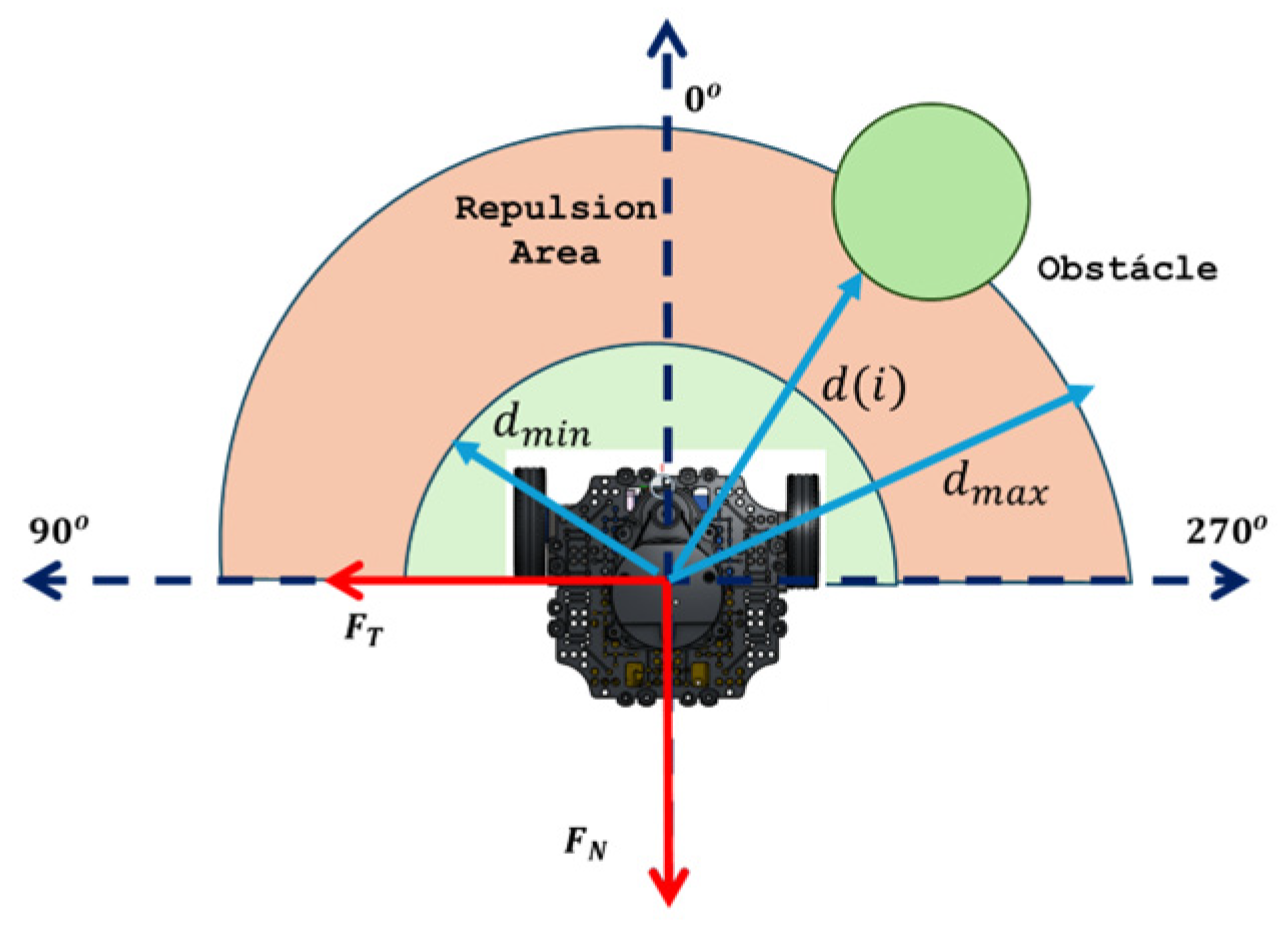
In order to avoid collisions with objects in congested environments, an avoidance algorithm was designed based on the generation of repulsive forces from measurements taken by the LIDAR sensor integrated into the Turtlebot3 Burger mobile robots. A repulsion area was defined as in Figure 2, and this range is valid for control purposes.
The algorithm calculates normal and tangential repulsive forces from the data captured by the LIDAR sensor. These forces are computed as weighted sums of the distances detected by the sensor, according to the following expressions:
F N = 1 F N m a x i = 0 n = 180 f i sin i ; F T = 1 F T m a x i = 0 n = 180 f i cos i
where f i = f m a x f m a x d m a x d m i n d ( i ) d m i n ; f m a x is the maximum feedback force supported by the Novint Falcon device, set to 10 N; d m i n = 0.10   m ; d m a x = 0.30   m , and d i represents the distance detected in the i t h direction. F N , F T denote the normal and tangential components of the repulsive force, while F N m a x = 0.6 and F T m a x = 0.9 correspond to the normalization thresholds, specified by the manufacturer according to the maximum operational displacement of the haptic actuator, and represent the upper bound of force within the repulsion zone. These forces are subsequently transformed into velocity signals for application to robot control:
U o b j = D N   F N ;   W o b j = K ϕ t a n h ( F T )
where U o b j , W o b j represent the linear and angular velocities of the induced evasion. To smooth the evasion control action, the gains D N and K ϕ are considered.

2.4. Modeling of the Induced Velocity

Bilateral teleoperation of the robot formation was enabled using the Novint Falcon haptic device, which sends motion commands and provides force feedback derived from the LIDAR-based force components in (8). The induced velocity is modeled through a mechanical impedance Z m , defined by mass M and damping D , relating applied force to resulting velocity U H I V [11].
U d = Z m   U H I V = M s 2 + D s s U H I V
where U d = u d , w d describes the desired velocity in he formation given by the haptic device and U H I V = u H I V , w H I V the induced velocity after mechanical impedance. Clearing U H I V gives:
U H I V = 1 M s + D U d
Figure 3a shows how the output evolves U H I V for different damping values D . The signals were scaled to stay within the physical limits of the Turtlebot3, corresponding to linear velocity: ± 0.2   m / s , and angular velocity: ± 1.8   r a d / s . Figure 3b shows the diagram of the assignment of these velocities.

3. Controllers

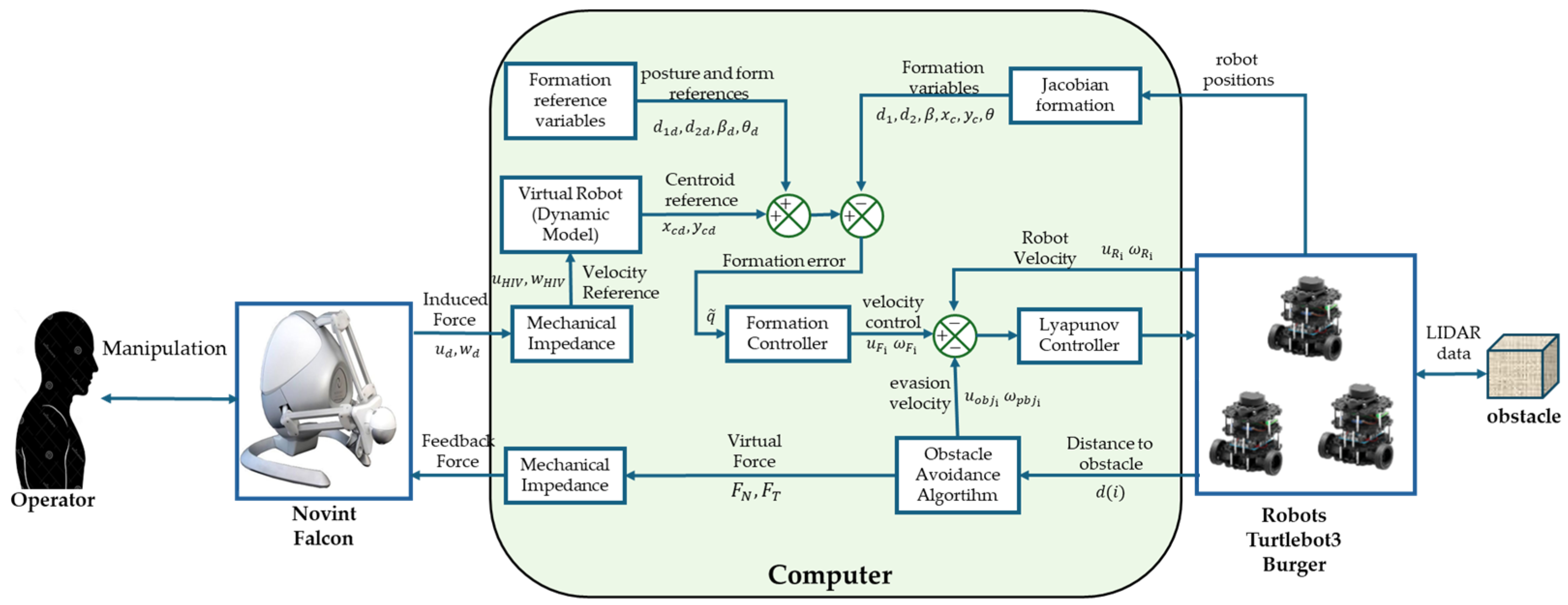
The proposed control architecture is shown in Figure 4, which depicts the cascaded structure consisting of an outer loop responsible for maintaining formation and an internal loop dedicated to obstacle avoidance.

3.1. Reference

The operator applies a force to the haptic device, which in turn generates an induced force u d , w d . Through the mechanical impedance model, this interaction produces a velocity reference for the virtual robot, denoted u V I H , w V I H . From these velocities, the reference positions of the formation centroid x c d , y c d are determined. The remaining desired positions for the robots in the formation are specified by the parameters d 1 d , d 2 d , β d , θ d , which together form the set of reference inputs to the formation controller.

3.2. Proportional-Type Formation Controller Design

The controller design for mobile robot formation is based on a Proportional strategy, whose objective is to ensure that the formation error converges to zero. The analysis relies on a Lyapunov candidate function to demonstrate the stability of the closed-loop system. Substituting (4) into (6) yields:
q ˙ = J F   J   U
To analyze the stability of the system, the following function is proposed as a Lyapunov candidate:
V q = 1 2 q T q
where q = q d q = d 1 , d 2 , β , x c , y c , θ T which is the error of the formation vector. Deriving with respect to time, we have:
V ˙ q = q T q ˙
The following Proportional control law (in this case purely proportional) is therefore proposed, defined as:
U F = J F   J 1 q d ˙ + K q
where K = d i a g ( K d 1 , K d 2 , K β , K x c , K y c , K θ ) is the positive diagonal matrix that allows the proportional gain to be adjusted in each formation variable. U F = [ u F 1   ω F 1   u F 2   ω F 2   u F 3   ω F 3 ] control actions of the Proportional controller. In a closed loop and assuming perfect velocity tracking, we have that U F = U , replacing (14) in (13), we have:
V ˙ q = q T K q
Since   K is a positive definite diagonal matrix, then V ˙ q 0 ; therefore, the formation error q 0   when t . Ensuring stability in the absence of obstacles.

3.3. Obstacle Avoidance Controller Design

Obstacle avoidance control is also designed using Lyapunov functions, considering auxiliary variables associated with velocity errors. Let ρ i an auxiliary variable to describe the linear velocity error u i of the i-th robot, with ρ i = ρ d i ρ i , the derivative of the error is defined as:
ρ ˙ i = u F i u R i u o b j ;   θ i ˙ = ω F i ω R i ω o b j
where u F i and ω F i represent the linear and angular formation control velocities, respectively. While u R i and ω R i describe the actual linear and angular velocities of the i-th robots, and u o b j and ω o b j denote the linear and angular velocities obtained from the repulsive forces. The following Lyapunov candidate is proposed:
V ρ i = 1 2 ρ i 2
Derivating (17) and substituting (16):
V ˙ ρ i = ρ i u F i u R i u o b j
To stabilize this error, the following saturated hyperbolic tangent nonlinear control law is proposed:
u R C i   = u F i + q ρ tanh k ρ ρ i q ρ u o b j
Assuming perfect tracking, that is u R C = u R , and substituting (21) into (20), this gives:
V ˙ ρ i = ρ i   q ρ   tanh k ρ ρ i q ρ
Since k ρ > 0 and q ρ > 0 , it is guaranteed that V ˙ ρ i 0 ,   therefore, ρ i 0 when t which ensures asymptotic stability. For analog formation control, the auxiliary error in orientation is considered θ i = ω F i ω R i ω o b j . The Lyapunov candidate is defined:
V θ i = 1 2 θ i 2
The proposed control law:
ω R C i = ω F i + q ω   tanh k ω θ i q ω ω o b j
Given that q ω > 0 and k ω > 0 it is concluded that V ˙ θ i 0 and therefore θ i 0 when t .

4. Experimental Tests and Results

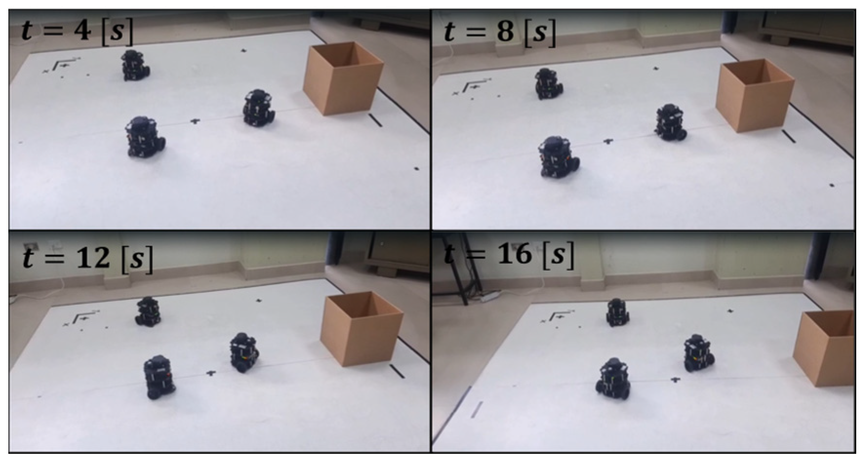
This section describes the experimental validation of the proposed control scheme for the formation and obstacle avoidance of a group of three mobile robots. The following initial conditions were taken into account for the experiment: the three robots were positioned at coordinates P 1 = ( 0 , 0.69 )   m , P 2 = 0.4 , 0   m , and P 3 = 0.4 , 0   m , thus forming an equilateral triangle with sides of 0.8   m . The total duration of the experiment was 16 s. The robot parameters were: a = 0.05   m ; T 1 = 0.3984 ; T 2 = 0.2523 ; T 3 = 0.0436 ; T 4 = 1.0069 ; T 5 = 0.0073 ; T 6 = 1.0693 . For the proportional formation controller, the diagonal gain matrix K = d i a g ( 1,1 , 0.5,1 , 1,1 ) was used. For the obstacle avoidance controller, the design parameters were set as k ρ = 0.5 , q p = 0.5 , k ω = 0.5 , and q ω = 0.5 . The mechanical impedance parameters were set as M = 0.3 and D = 1 . A repulsion area of 30   c m was defined. The evolution of the formation during the experiment can be seen in Figure 5, which shows snapshots at four representative moments: t = 4   s ,   t = 8   s ,   t = 12   s , and t = 16   s . These moments reflect the behavior of the system both in terms of convergence to the desired formation and in terms of response to obstacles.
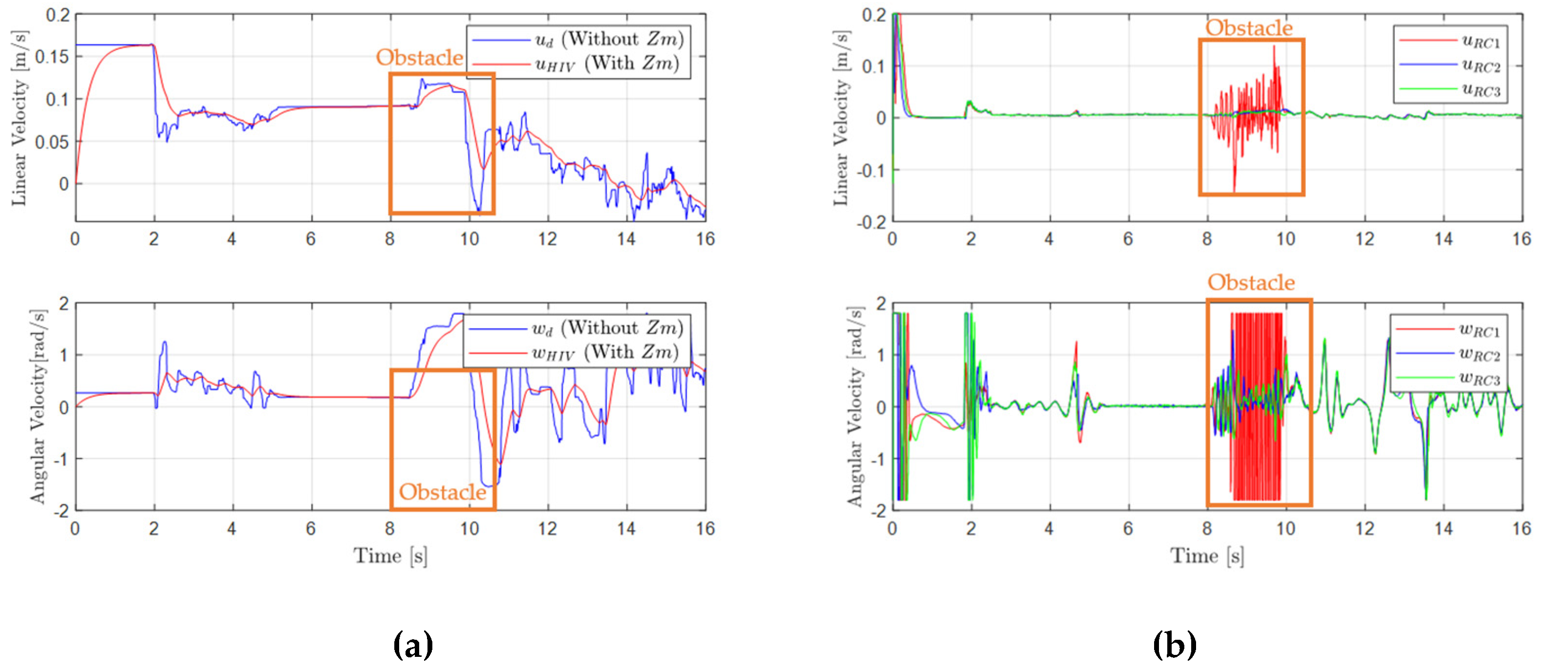
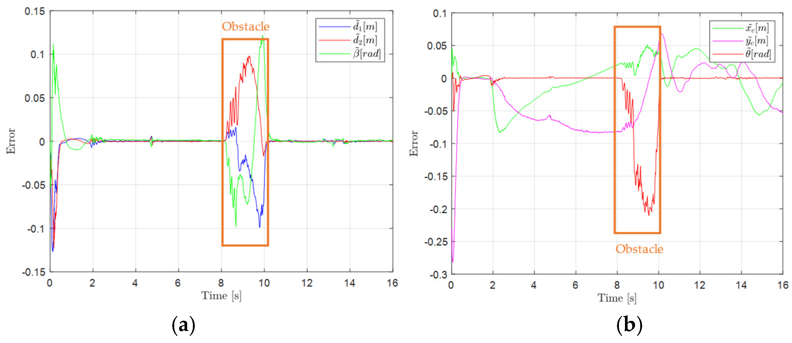
Figure 6a compares the velocities induced by the Novint Falcon joystick with and without the mechanical impedance model Z m . Incorporating Z m produces smoother, more continuous responses, damping user actions and enhancing stable human–robot interaction. Figure 6b shows the linear and angular velocities of each robot. Between t   =   8 s and t = 10 s, robot 1 exhibits a velocity change coinciding with obstacle detection, reflecting the action of the obstacle avoidance controller. Figure 7a,b show the evolution of the normal ( F N 1 ) and tangential ( F T 1 ) repulsion forces on robot 1. As the obstacle approaches, F N 1 slows the robot linearly, while F T 1 induces angular velocity oscillations, representing the dynamic compromise between collision avoidance and formation maintenance. Figure 8a,b show the errors associated with the shape and posture variables, respectively. During the first 8   s of the experiment, the errors remain low, indicating stable behavior and a well-maintained formation. However, between t = 8   s and t = 10   s , coinciding with the appearance of an obstacle. Once the obstacle leaves the repulsion area, the errors decrease rapidly, demonstrating the formation controller’s ability to efficiently recover the desired configuration.

5. Conclusions

In this work, the experimental results confirm the effectiveness of the proposed bilateral teleoperation strategy for the coordinated control of a formation of mobile robots with obstacle avoidance. The integration of a Proportional-based cascade control structure combining formation maintenance and obstacle evasion enabled stable group behavior even in the presence of environmental disturbances. The use of the Novint Falcon haptic device, together with mechanical impedance modeling, resulted in smoother and more stable velocity commands, enhancing human–robot interaction. During the experiment, the system demonstrated accurate formation tracking, responsive obstacle avoidance, and rapid recovery of formation integrity after perturbations. The evolution of forces and velocities revealed a coordinated dynamic response, with shape and posture errors remaining low throughout most of the task, validating the robustness and practical applicability of the proposed control approach in real-world scenarios. Under unilateral teleoperation, quantitative comparisons between controllers are limited by human variability, and the system is not able to address formation reconfiguration or scalability; both of these issues are left for future work. The approach shows limited effectiveness with dynamic obstacles, motivating the exploration of advanced avoidance strategies. Experiments considered a fixed 0.1 s communication delay, which did not affect performance, but variable wireless delays (e.g., Wi-Fi) may compromise stability; future work will incorporate delay-compensation strategies for robust real-world operation.

Author Contributions

Conceptualization, G.M.A. and P.L.; investigation and methodology, J.C., and P.L.; design of control laws, J.C. and P.L.; software and validation, J.C.; writing—original draft preparation, J.C.; writing—review and editing, G.M.A., O.C. and P.L.; supervision, P.L. All authors have read and agreed to the published version of the manuscript.

Funding

This research received no external funding.

Institutional Review Board Statement

Not applicable.

Informed Consent Statement

Not applicable.

Data Availability Statement

Data are contained within the article.

Acknowledgments

The authors acknowledge the technical support of the Escuela Politécnica Nacional through Project PIS-23-09, Artificial Intelligence Techniques Applied to an Aerial Manipulator in Semi-structured Environments. The authors also thank the GIECAR research group for their valuable theoretical and technical contributions.

Conflicts of Interest

The authors declare no conflicts of interest.

References

  1. Slawiñski, E.; Santiago, D.; Mut, V. Dual coordination for bilateral teleoperation of a mobile robot with time varying delay. IEEE Lat. Am. Trans. 2020, 18, 1777–1784. [Google Scholar] [CrossRef]
  2. Tarn, T.; Bejczy, A.; Xi, N.; Ramadorai, A. Distributed control architecture for a sensor-driven dual arm system. Mechatronics 1994, 4, 481–502. [Google Scholar] [CrossRef]
  3. Patiño, K.; Slawiñski, E.; Moran-Armenta, M.; Mut, V.; Rossomando, F.G.; Moreno-Valenzuela, J. Neural networks in the delayed teleoperation of a skid-steering robot. Mathematics 2025, 13, 2071. [Google Scholar] [CrossRef]
  4. Karbasizadeh, N.; Aflakiyan, A.; Zarei, M.; Masouleh, M.T.; Kalhor, A. Dynamic identification of the Novint Falcon Haptic device. In Proceedings of the 2016 4th International Conference on Robotics and Mechatronics (ICROM), Tehran, Iran, 26–28 October 2016; pp. 518–523. [Google Scholar] [CrossRef]
  5. Renon, P.; Yang, C.; Ma, H.; Cui, R. Haptic interaction between human and virtual iCub robot using Novint Falcon with CHAI3D and MATLAB. In Proceedings of the 32nd Chinese Control Conference, Xi’an, China, 26–28 July 2013; pp. 6045–6050. [Google Scholar]
  6. Li, Y.; Chai, L.; Wu, C. Multi-robot formation obstacle avoidance based on virtual robots and improved artificial potential fields. In Proceedings of the 2024 China Automation Congress (CAC), Qingdao, China, 1–3 November 2024; pp. 1861–1866. [Google Scholar] [CrossRef]
  7. Xi, N.; Tarn, T.; Bejczy, A. Event-based planning and control for multi-robot coordination. In Proceedings of the IEEE International Conference on Robotics and Automation (ICRA), Atlanta, GA, USA, 2–6 May 1993; Volume 1, pp. 251–258. [Google Scholar] [CrossRef]
  8. Lima, A.; Gouvea, J.A.; Lizarralde, F.; Hsu, L. Trajectory tracking, pose regulation and adaptive formation control of a group of nonholonomic mobile robots. IFAC Proc. Vol. 2014, 47, 5709–5714. [Google Scholar] [CrossRef]
  9. Zolotas, A.; Antonelli, G.; Chiaverini, S. A survey on formation control in robotics. Annu. Rev. Control. 2019, 48, 242–249. [Google Scholar] [CrossRef]
  10. Jacob M, J.; Dinesh, A.; Mulla, A.K. On bilateral teleoperation of multi-agent systems: Bearing-based formation tracking control. In Proceedings of the 2022 Eighth Indian Control Conference (ICC), Chennai, India, 14–16 December 2022; pp. 67–72. [Google Scholar] [CrossRef]
  11. Riera, J.; Daquilema, E.; Andaluz, G.M.; Leica, P. Teleoperation of the TurtleBot Mobile Robot using an SMC controller in environments with obstacles. In Proceedings of the 2024 IEEE Eighth Ecuador Technical Chapters Meeting (ETCM), Cuenca, Ecuador, 15–18 October 2024; pp. 1–6. [Google Scholar] [CrossRef]
  12. Dong, N.; Hu, J.; Li, J.; Shi, J.; Tan, L.; Lin, Y. A Position-Based Impedance Control Strategy of Bilateral Teleoperation System with Force Feedback. In Proceedings of the 2021 China Automation Congress (CAC), Beijing, China, 22–24 October 2021; pp. 6924–6929. [Google Scholar] [CrossRef]
  13. Neumann, M.A.; Kitts, C.A. A hybrid multirobot control architecture for object transport. IEEE/ASME Trans. Mechatron. 2016, 21, 2983–2988. [Google Scholar] [CrossRef]
  14. Cheong, J.; Niculescu, S.-I. Robust motion synchronization control for interconnected systems with human interaction. IFAC Proc. Vol. 2008, 41, 6347–6352. [Google Scholar] [CrossRef]
  15. Leica, P.; Rivera, K.; Muela, S.; Chavez, D.; Andaluz, G.; Andaluz, V.H. Consensus algorithms for bidirectional teleoperation of aerial manipulator robots in an environment with obstacles. In Proceedings of the 2019 IEEE Fourth Ecuador Technical Chapters Meeting (ETCM), Guayaquil, Ecuador, 11–15 November 2019; pp. 1–6. [Google Scholar] [CrossRef]
  16. Andaluz, G.M.; Andaluz, V.H.; Terán, H.C.; Arteaga, O.; Chicaiza, F.A.; Varela, J.; Ortiz, J.S.; Pérez, F.; Rivas, D.; Sánchez, J.S.; et al. Modeling dynamic of the human-wheelchair system applied to NMPC. In Intelligent Robotics and Applications; Springer: Cham, Switzerland, 2016; pp. 179–190. [Google Scholar] [CrossRef]
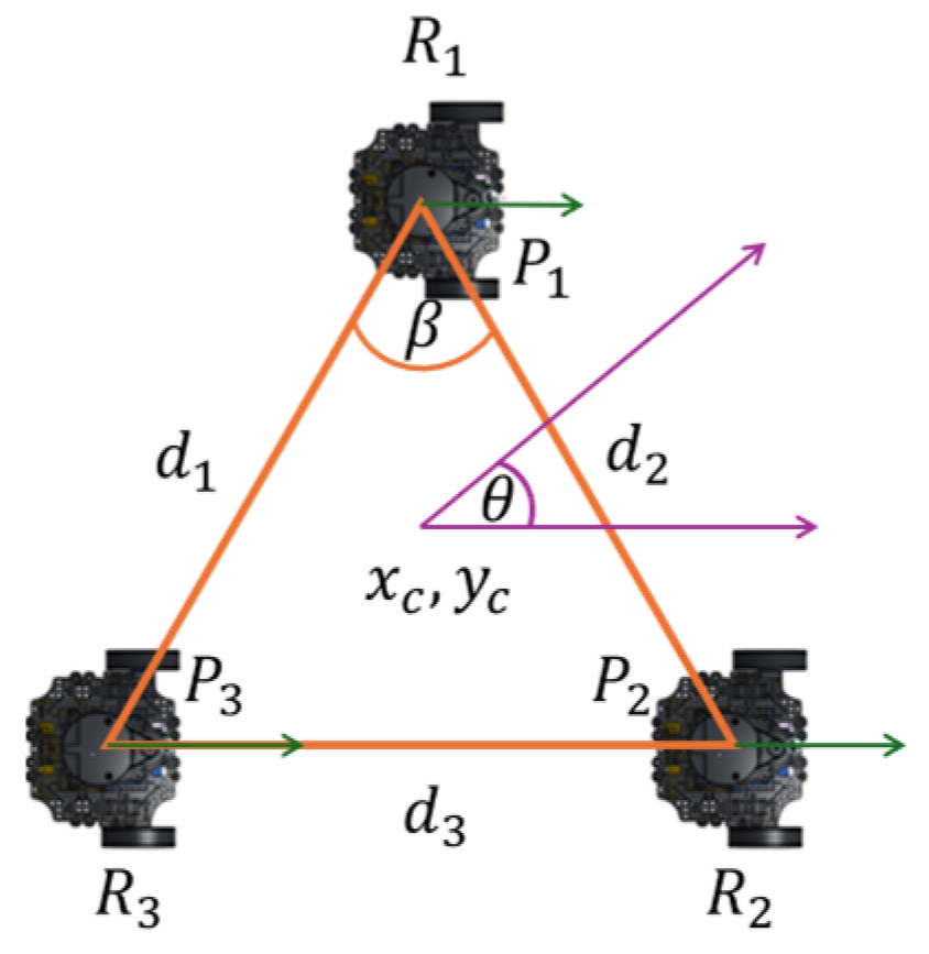
Figure 1. Triangular arrangement of the formation of three mobile robots.
Engproc 115 00010 g001
Figure 2. Representation of the repulsion area.
Engproc 115 00010 g002
Figure 3. (a) Evolution of U H I V for different damping values D con M = 0.3 . (b) Linear and angular velocities assignment.
Engproc 115 00010 g003
Figure 4. Robot formation control scheme with obstacle avoidance.
Engproc 115 00010 g004
Figure 5. Experimental evaluation at multiple time instances.
Engproc 115 00010 g005
Figure 6. (a) Comparison between Novint Falcon and the reference velocities. (b) Control Signals: u R C i and ω R C i .
Engproc 115 00010 g006
Figure 7. (a) Normal Forces ( F N i ) and Linear Velocities ( u R i ) of each robot. (b) Tangential Forces ( F T i ) and Linear Velocities ( u R i ) of each robot.
Engproc 115 00010 g007
Figure 8. (a) Shape Errors d 1 ,   d 2 , and β . (b) Posture Errors x c ,   y c , and θ .
Engproc 115 00010 g008
Disclaimer/Publisher’s Note: The statements, opinions and data contained in all publications are solely those of the individual author(s) and contributor(s) and not of MDPI and/or the editor(s). MDPI and/or the editor(s) disclaim responsibility for any injury to people or property resulting from any ideas, methods, instructions or products referred to in the content.