1. Introduction
In recent years, automatic camera orientation systems have gained attention for applications requiring precise tracking and centering of targets, such as human faces. These systems combine computer vision, control algorithms, and mechanical actuation to adjust camera position in real time based on object detection.
Active object tracking has evolved to address various challenges, including time delays [
1], occlusions, and dynamic environments. For instance, Li et al. [
2] introduced a pose-assisted multi-camera collaboration system in which each camera employs both vision-based and pose-based controllers. A switching mechanism selects the optimal controller based on target visibility, thereby enhancing tracking performance in complex scenarios. In single-camera systems, convolutional neural networks have been employed to estimate head orientation. Sobański et al. [
3] proposed a method capable of predicting vertical and horizontal head orientations, enabling real-time control of a two-degree-of-freedom camera mount. This approach allows the camera to adjust its orientation based on the detected head pose, maintaining the face at the center of the image. Similarly, Singh et al. [
4] presented the design and implementation of an FPGA-based standalone prototype for real-time object tracking in live video streams. Their system enables automatic pan–tilt camera movement in response to the tracked object’s motion.
Optimizing camera placement and orientation is essential for accurate face tracking. Alsadik et al. [
5] proposed a mathematical optimization method for camera arrays used in 3D face modeling, considering constraints such as baseline-to-height (B/H) ratios and angles of incidence to minimize reconstruction errors. Giriyan et al. [
6] explored optimal camera placement strategies to ensure full coverage of multiple individuals in a room.
Control strategies play a pivotal role in object tracking, as precise camera movements require robust algorithms. Wu et al. [
7] introduced an intelligent positioning system capable of integrating visual data from numerous cameras through self-configuration, using an extended Kalman filter. Predictive control strategies have also been applied to pan–tilt camera systems. Nebeluk et al. [
8] compared PID, Dynamic Matrix Control (DMC), and Generalized Predictive Control (GPC), demonstrating that specific controllers can outperform others in predictive tracking tasks. Guo et al. [
9] proposed a novel visual servoing scheme for a miniature pan–tilt inertially stabilized platform.
Simulation tools are instrumental in the design and validation of such systems. Sim4CV [
10], a photorealistic simulator, facilitates the training and evaluation of computer vision applications, including autonomous UAV tracking and driving. Tang et al. [
11] introduced a dual control structure for coordinated trajectory tracking—addressing both motion and force—of a mobile robot.
The present paper aims to develop an automatic camera orientation system based on the spatial positioning of an object of interest, with a specific focus on centering a human face within the image frame.
2. Methodology
The face-tracking pan–tilt system tackles two main challenges: real-time face detection within an image and camera reorientation to keep the face centered. This is achieved through three key components: a computer vision module for detection, a control system for computing corrections, and a mechanical pan–tilt platform for executing camera adjustments.
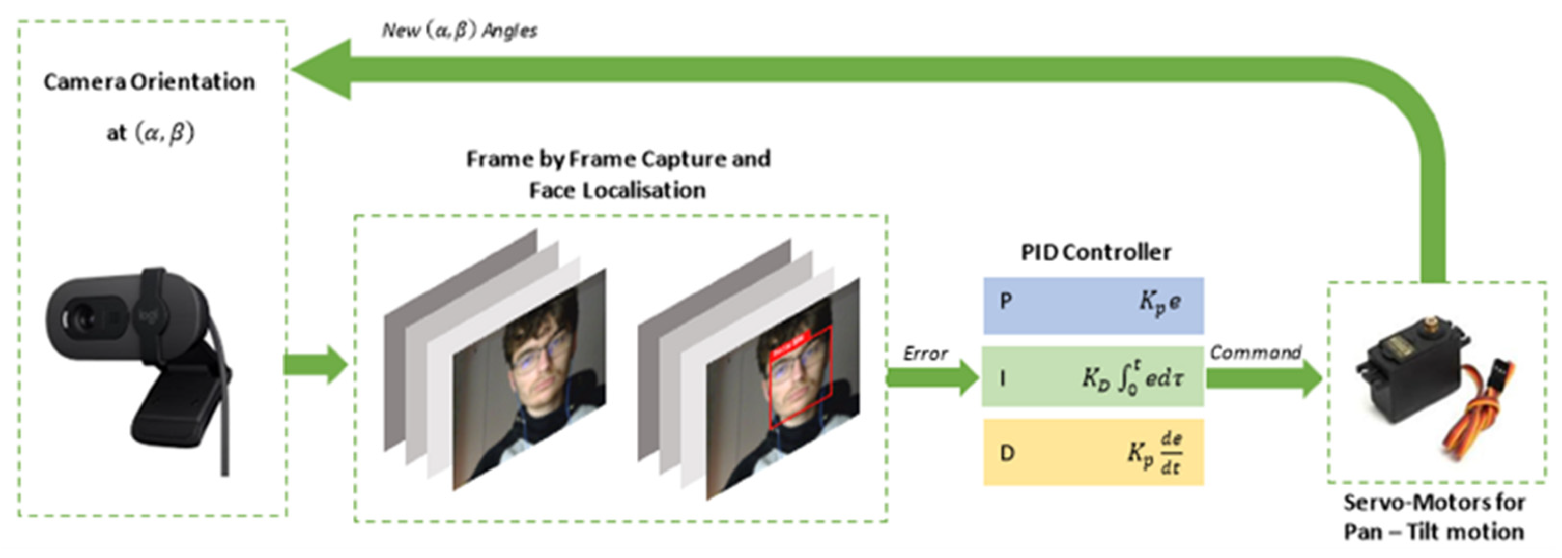
The system operates within a closed-loop control structure, as illustrated in
Figure 1. The system consists of the following sequence: the camera captures an image of the environment at each discrete time step
, the face detection module processes the image and determines the face’s centroid coordinates (
) in the image plane; the error computation module calculates the difference between the face position and the center of the image frame, (
) the PID controllers for the pan and tilt axes generate command signals based on the computed errors, the servo motors actuate the pan and tilt movements to reduce the tracking error.
The system error is defined as:
where
,
are face position coordinates at time
, and
are the center coordinates of the image. The goal is to minimize
and
over time.
2.1. System Modelling
The block diagram from
Figure 1 illustrates the operational flow: the camera captures real-time images, the detection model extracts object coordinates, and a PID controller computes the necessary angular adjustments for the motors. These adjustments reorient the camera so that the target object remains centrally located in the image.
The servo motors used in this system are MG996R models, selected for their reliability and adequate mechanical performance. The modeling process involves deriving differential equations that represent both the electrical and mechanical dynamics of the motor. These equations are subsequently transformed into the Laplace domain to facilitate system analysis and controller design.
The final servo model, depicted in
Figure 2, incorporates key components, including the DC motor, gear reducer, and internal control logic, comprising a microcontroller that interprets PWM signals and provides feedback via a potentiometer. To approximate the internal control behavior, a hyperbolic tangent function is employed, which models the nonlinear relationship between the angular error and the control response.
Further, the camera is modelled using principles of projective geometry, transforming 3D spatial coordinates into 2D image coordinates based on the focal length and sensor dimensions, as described in
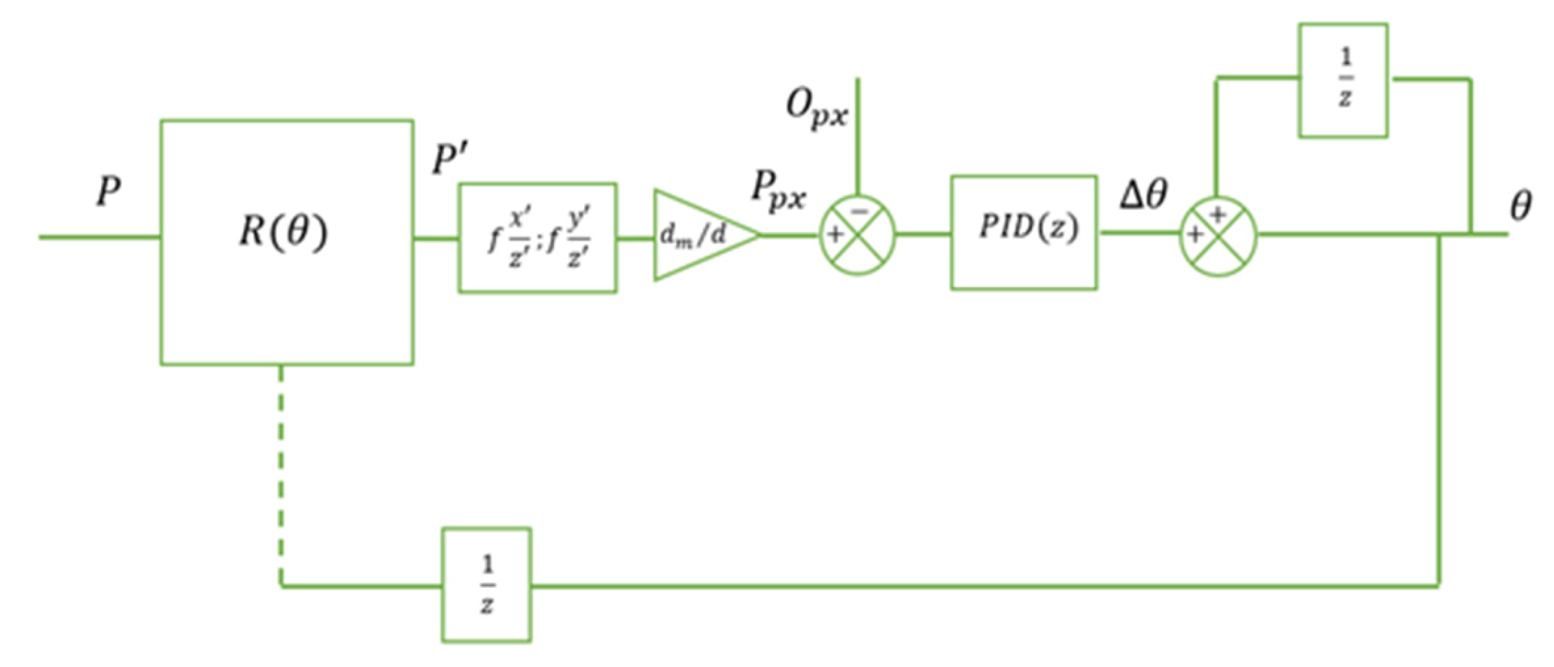
Figure 3. This model enables the system to determine the pixel coordinates of the detected face and compute its displacement from the center of the image. Further, the block diagram of the orientation system is modelled in
Figure 4.
Separate models are constructed for horizontal (pan) and vertical (tilt) movements due to the independent nature of these rotations. By changing the orientation in both pan and tilt directions, the position of point P in 3D space also changes, leading to further changes in the position of the 2D projection of P’ on the image plane.
2.2. The Face Detection Module
The face detection module is based on a deep learning model of the YOLO (You Only Look Once) family, known for its real-time capabilities [
12]. A YOLOv5s architecture was selected due to its balance between detection accuracy and computational efficiency.
The detection process operates as follows: given an input image , the network outputs a set of bounding boxes each characterized by center coordinates width , and height . Among multiple detected faces, the system selects the bounding box with the highest confidence score.
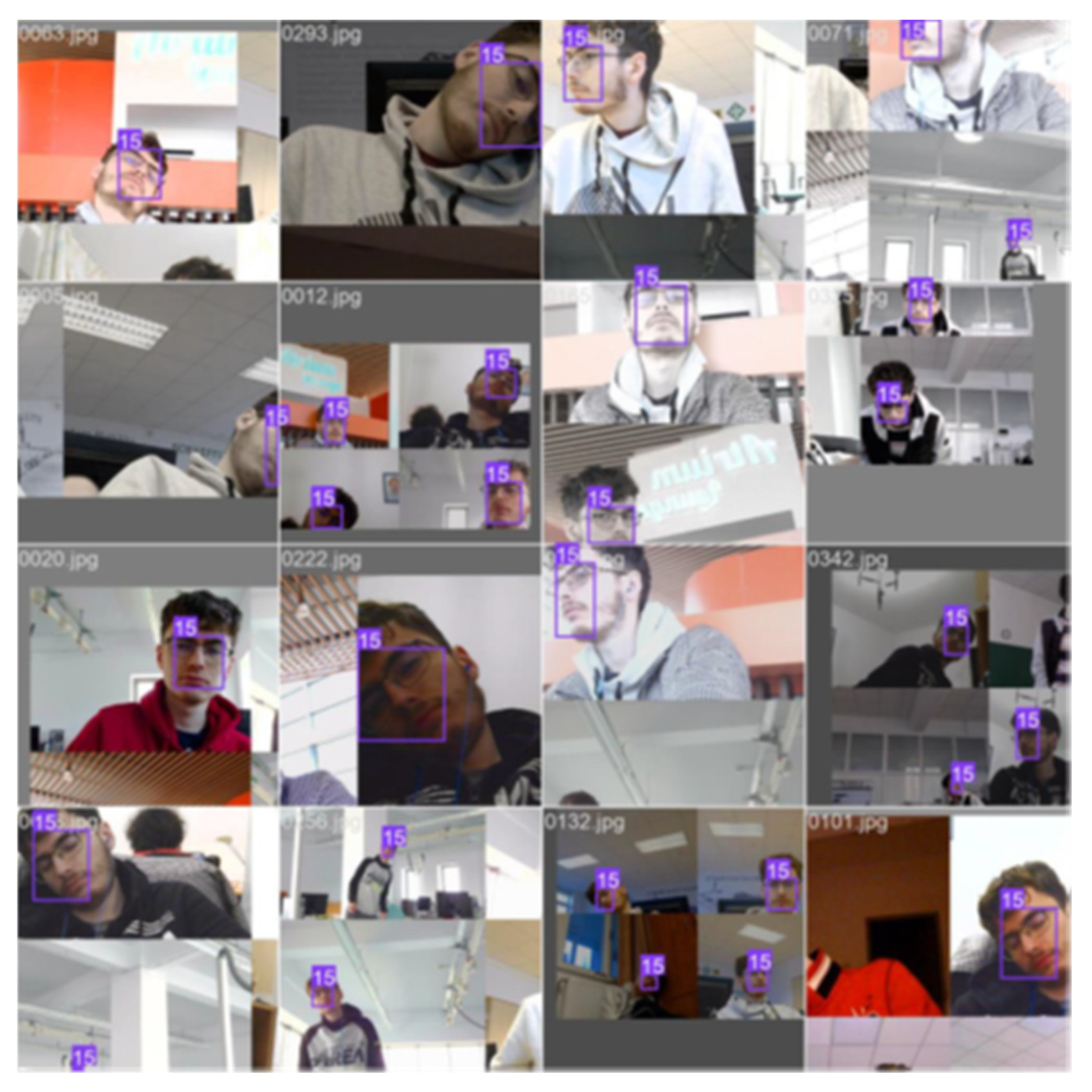
The model was trained on a custom face dataset containing 376 images (samples are depicted in
Figure 5), achieving the following metrics: mean average precision at 50% IoU (mAP@50): 99.5%, and mean average precision averaged over IoU thresholds (mAP@50-95): 73.2%.
The face center
is extracted from the bounding box as:
Real-time operation constraints the maximum allowed inference time
to:
where
is the control loop sampling frequency.
The training samples were preprocessed with resizing and augmentation to enhance model robustness. Training was performed on a GPU using PyTorch 2.9.0, and metrics like precision and mAP (mean average precision) were monitored to ensure high detection accuracy. This tailored approach optimized the model for real-time face detection.
2.3. Pan–Tilt Mechanical Platform
The mechanical platform provides two rotational degrees of freedom (DoF): pan () and tilt (). Each DoF is actuated by an MG996R servo motor, characterized by stall torque = 11 kgf/cm at 6 V, no-load rotation speed of 0.16 s/60°.
The pan–tilt system is designed to maximize the angular workspace while minimizing mass and mechanical redundancy. Servo motors are modeled using standard DC motor equations:
electrical model:
where
is the applied voltage,
the armature resistance,
the armature inductance,
armature current, and
is the back electromotive force.
mechanical model:
where
is the motor torque,
is the total rotational inertia,
viscous friction coefficient,
is the load torque.
The pan and tilt axes are equipped with lightweight PLA support structures, with mechanical parameters (moments of inertia) determined via CAD modeling.
2.4. The PID Control System
Each servo axis is controlled by a separate PID controller, following the control law:
where
is the tracking error (
for pan,
for tilt),
is the command signal to the servo motor,
are the proportional, integral, and derivative gains.
The controller gains were initially tuned using the Ziegler–Nichols method, based on determining the ultimate gain
and ultimate period
. For instance, the classic PID tuning rules provide:
The final tuning values were refined to ensure minimal overshoot (<5%), fast settling time, robustness against disturbances or multiple faces entering the frame.
3. Results
The results are categorized into three key performance areas: face detection accuracy, control system responsiveness, and the mechanical stability of the tracking mechanism.
3.1. Experimental Setup
The proposed system was implemented on a hardware platform comprising a Logitech Brio 100 camera and a pan–tilt unit actuated by two MG996R servo motors. Control and image processing routines were executed on a laptop running a custom software stack designed to manage frame acquisition, face detection, error computation, and PID control. The camera operated at a resolution of 640 by 480 pixels and a frame rate of 30 frames per second. To assess the real-time behavior of the control loop, we performed logging of timestamped execution intervals over a continuous period. The loop consistently maintained an average frequency of 20.1 Hz, with a standard deviation of approximately ±0.3 Hz (see
Figure 6). This result confirms that the control algorithm operates with high timing stability and is capable of sustaining real-time responsiveness under typical operating conditions.
Testing was conducted in an indoor environment under various conditions, including the presence of single and multiple human faces, dynamic head movements, and moderate fluctuations in ambient lighting. Each test was designed to evaluate specific performance indicators such as detection reliability, convergence speed, and tracking stability.
3.2. Face Detection Performance
The YOLOv5n-based face detection module demonstrated high precision and recall, confirming its suitability for real-time tracking applications. The model was trained on a dataset of 376 annotated images, 360 for training and 16 for validation, and achieved a mean Average Precision (mAP) of 99.5% at a 50% Intersection over Union (IoU) threshold, and 73.2% for mAP@50-95. The average inference time per frame was approximately 32 ms, allowing seamless integration into the closed-loop control system.
The model provided robust detections across a range of head poses, partial occlusions, and non-uniform backgrounds. In scenarios involving multiple faces within the field of view, the system consistently prioritized the dominant target based on bounding box area and temporal continuity. The bounding box coordinates enabled accurate extraction of the face center, which served as the input for the control algorithm.
3.3. Tracking Dynamics and Controller Response
The dynamic response of the PID-controlled pan–tilt mechanism was evaluated by manually displacing the target subject and observing the system’s ability to recenter the face. For both the pan and tilt axes, the controllers exhibited smooth transient behavior, characterized by minimal overshoot and rapid convergence to steady state.
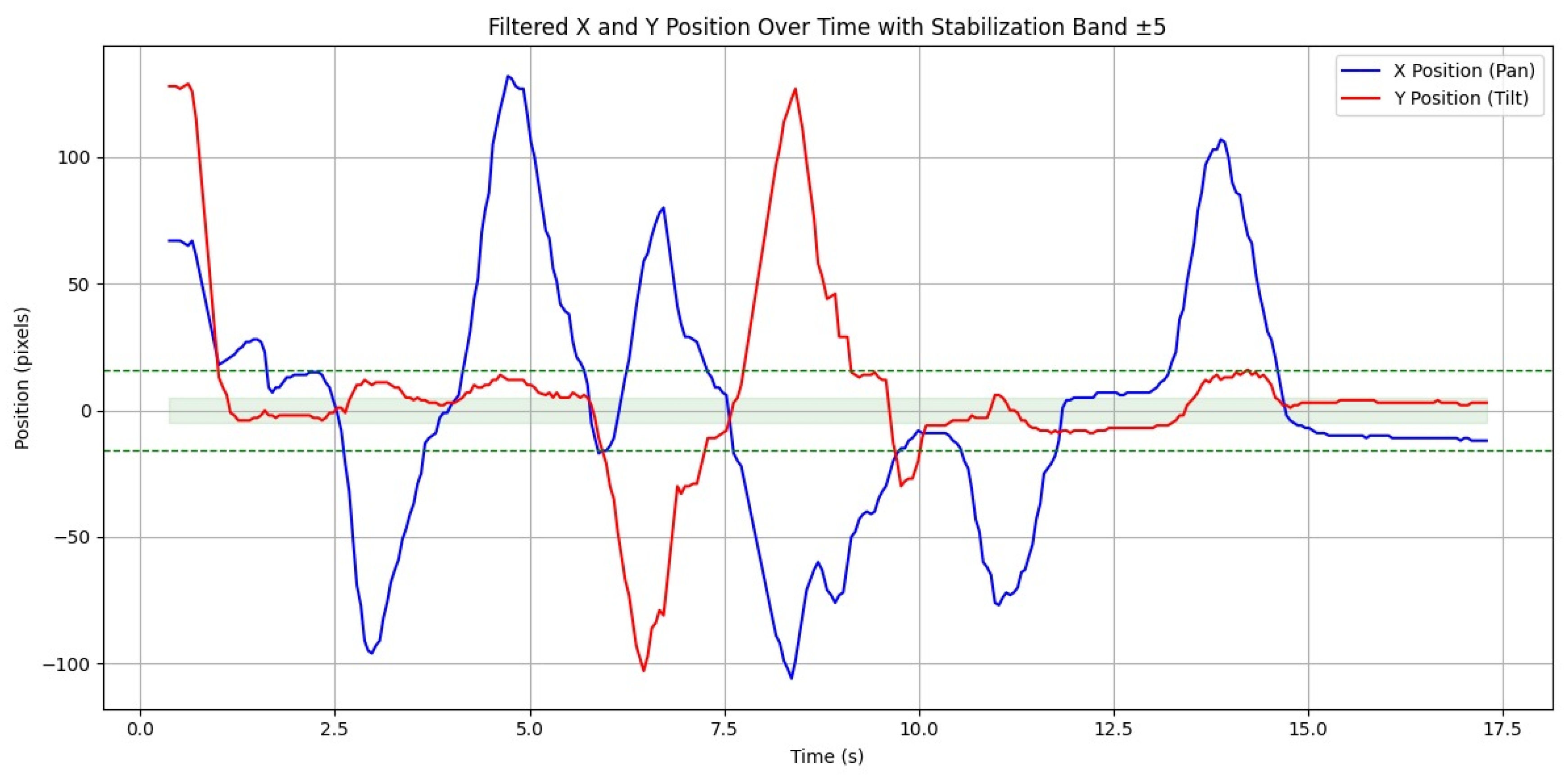
Quantitatively, the settling time for the pan axis was approximately 0.95 s, while the tilt axis stabilized within about 1.10 s, maintaining a ±5-pixel margin around the image center. Overshoot remained below 5% in both cases, and the steady-state error consistently stayed under 4 pixels. These results confirm that the tuning method, initially based on Ziegler–Nichols parameters and subsequently refined through empirical adjustments, produced effective control gains.
Figure 6 illustrates the temporal evolution of the control error and servo angle during a representative tracking scenario. The response curves highlight the system’s ability to adapt swiftly to abrupt positional changes of the target.
4. Discussion
The system was thoroughly tested under various conditions, showing robust and reliable performance. During rapid head movements, it maintained tracking with minor deviations, re-centering the face within about one second. Under moderate motion, the face stayed within a 10-pixel margin. In dim lighting, detection confidence dropped slightly, affecting tracking speed. Preliminary observations indicate that detection confidence decreases in dim lighting, which affects tracking responsiveness. To improve robustness, future iterations may integrate dynamic exposure control and augment the dataset with synthetic lighting conditions. Moreover, adding training samples with varied face orientations could improve generalization beyond the current limited dataset.
The system also exhibited resilience to temporary occlusions. When the face was momentarily obscured and subsequently reappeared, tracking resumed automatically without requiring a system reset. Furthermore, the software architecture incorporated a short-term buffering mechanism that smoothed out detection interruptions of up to three consecutive frames, thereby preventing unnecessary servo oscillations.
The PID controller was selected due to its simplicity, low computational cost, and ease of tuning—important factors for real-time embedded control with limited processing power. While more advanced methods like Model Predictive Control (MPC) or fuzzy logic offer better adaptability in nonlinear conditions, their implementation on lightweight systems would increase complexity and latency.
Several limitations were noted. In low-light conditions, the detector’s confidence dropped, and inference slowed, delaying control response. Mechanical backlash in the MG996R servos caused occasional jitters during fine adjustments near steady state. Additionally, when multiple faces were equally distant, the lack of identity tracking led to brief oscillations between targets until one became dominant.
5. Conclusions
The developed face-tracking pan–tilt system demonstrates effective real-time performance through the integration of YOLOv5-based face detection and PID-controlled servo actuation. Experimental results validate the system’s ability to maintain accurate face positioning under dynamic conditions and moderate lighting variations. The system’s modular architecture supports extensibility, making it a versatile platform for a wide range of applications, including human–robot interaction and automated surveillance.
While the system exhibits robust performance, certain challenges remain, particularly in low-light environments and scenarios involving multiple faces. Future improvements could focus on enhancing detection robustness, incorporating identity tracking mechanisms, and refining mechanical stability through higher-precision actuators or software-based compensation techniques.
Author Contributions
Conceptualization, M.D.D. and T.-T.C.; methodology, M.D.D.; software, M.D.D.; validation, I.-A.S. and I.I.; formal analysis, G.M.; investigation, G.M.; writing—original draft preparation, B.S.; writing—review and editing, B.S.; supervision, T.-T.C.; project administration, T.-T.C. All authors have read and agreed to the published version of the manuscript.
Funding
This research received no external funding.
Institutional Review Board Statement
The study was conducted in accordance with the Declaration of Helsinki, and the protocol was approved by the Ethics Committee of Robotics Research Group on 19 November 2025.
Informed Consent Statement
Verbal informed consent was obtained from the participants. Verbal consent was obtained rather than written because the participant appearing in the images is the first author of this paper.
Data Availability Statement
The data presented in this study are available upon request from the corresponding author.
Acknowledgments
The author wishes to acknowledge the valuable support and guidance provided by Claudiu Pozna. Additionally, gratitude is expressed to Transilvania University of Brașov, for providing the necessary infrastructure and resources to facilitate this research.
Conflicts of Interest
The authors declare no conflicts of interest. The funders had no role in the design of the study; in the collection, analyses, or interpretation of data; in the writing of the manuscript; or in the decision to publish the results.
References
- Macesanu, G.; Comnac, V.; Moldoveanu, F.; Grigorescu, S.M. A Time-Delay Control Approach for a Stereo Vision Based Human-Machine Interaction System. J. Intell. Robot. Syst. 2014, 76, 297–313. [Google Scholar] [CrossRef]
- Li, J.; Xu, J.; Zhong, F.; Kong, X.; Qiao, Y.; Wang, Y. Pose-Assisted Multi-Camera Collaboration for Active Object Tracking. In Proceedings of the Thirty-Fourth AAAI Conference on Artificial Intelligence (AAAI-20), New York, NY, USA, 7–12 February 2020. [Google Scholar]
- Sobański, R.M.; Drążkowska, M.; Papis, M.; Stankiewicz, A. Application of Convolutional Neural Networks in Visual Feedback of Movable Camera Mounting Control. Appl. Sci. 2022, 12, 5252. [Google Scholar] [CrossRef]
- Singh, S.; Shekhar, C.; Vohra, A. Real-Time FPGA-Based Object Tracker with Automatic Pan-Tilt Features for Smart Video Surveillance Systems. J. Imaging 2017, 3, 18. [Google Scholar] [CrossRef]
- Alsadik, B.; Spreeuwers, L.; Dadrass Javan, F.; Manterola, N. Mathematical Camera Array Optimization for Face 3D Modeling Application. Sensors 2023, 23, 9776. [Google Scholar] [CrossRef] [PubMed]
- Giriyan, D.; Vinaykumar, C.; Somanna, B.; Abhishek, G.R. Investigation of Camera Placement and Face Detection Methods for Automated Camera-Based Attendance Systems. Int. J. Eng. Res. Technol. 2020, 8, 92–99. [Google Scholar] [CrossRef]
- Wu, Y.; Zhao, W.; Zhang, J. Methodology for Large-Scale Camera Positioning to Enable Intelligent Self-Configuration. Sensors 2022, 22, 5806. [Google Scholar] [CrossRef] [PubMed]
- Nebeluk, R.; Zarzycki, K.; Seredyński, D.; Chaber, P.; Figat, M.; Domański, P.D.; Zieliński, C. Predictive Tracking of an Object by a Pan–Tilt Camera of a Robot. Nonlinear Dyn. 2023, 111, 8383–8395. [Google Scholar] [CrossRef]
- Guo, J.; Yuan, C.; Zhang, X.; Chen, F. Vision-Based Target Detection and Tracking for a Miniature Pan-Tilt Inertially Stabilized Platform. Electronics 2021, 10, 2243. [Google Scholar] [CrossRef]
- Müller, M.; Casser, V.; Lahoud, J.; Smith, N.; Ghanem, B. Sim4CV: A Photo-Realistic Simulator for Computer Vision Applications. Int. J. Comput. Vis. 2018, 126, 902–919. [Google Scholar] [CrossRef]
- Tang, M.; Tang, K.; Zhang, Y.; Qiu, J.; Chen, X. Motion/Force Coordinated Trajectory Tracking Control of Nonholonomic Wheeled Mobile Robot via LMPC-AISMC Strategy. Sci. Rep. 2024, 14, 18504. [Google Scholar] [CrossRef] [PubMed]
- Redmon, J.; Divvala, S.; Girshick, R.; Farhadi, A. You Only Look Once: Unified, Real-Time Object Detection. In Proceedings of the IEEE Conference on Computer Vision and Pattern Recognition (CVPR), Las Vegas, NV, USA, 27–30 June 2016; pp. 779–788. [Google Scholar] [CrossRef]
| Disclaimer/Publisher’s Note: The statements, opinions and data contained in all publications are solely those of the individual author(s) and contributor(s) and not of MDPI and/or the editor(s). MDPI and/or the editor(s) disclaim responsibility for any injury to people or property resulting from any ideas, methods, instructions or products referred to in the content. |
© 2025 by the authors. Licensee MDPI, Basel, Switzerland. This article is an open access article distributed under the terms and conditions of the Creative Commons Attribution (CC BY) license (https://creativecommons.org/licenses/by/4.0/).


