Abstract
During the development of vehicle control algorithms, effective real-world validation is crucial. Model vehicle platforms provide a cost-effective and accessible method for such testing. The open-source F1Tenth project is a popular choice, but its reliance on lidar sensors limits certain applications. To enable more universal environmental perception, integrating a stereo camera system could be advantageous, although existing software packages do not yet support this functionality. Therefore, our research focuses on developing a modular software architecture for the F1Tenth platform, incorporating real-time stereo vision-based environment perception, robust state representation, and clear actuator interfaces. The system simplifies the integration and testing of control algorithms, while minimizing the simulation-to-reality gap. The framework’s operation is demonstrated through a real-world control problem. Environmental sensing, representation, and the control method combine classical and deep learning techniques to ensure real-time performance and robust operation. Our platform facilitates real-world testing and is suitable for validating research projects.
1. Introduction
The development and validation of vehicle control algorithms in real-world environments are essential yet challenging tasks. Testing on full-scale vehicles often involves significant logistical problems, high operational costs, and safety concerns, especially when dealing with experimental software components. These constraints can limit the frequency of real-world tests, slowing down research and innovation. In contrast, model-scale vehicle platforms offer a practical and efficient alternative for iterative development and testing. By imitating the key dynamics and perception challenges of full-sized vehicles, they enable researchers to conduct experiments in a controlled and reproducible manner, with drastically reduced risk and cost. Among such platforms, the F1Tenth open-source framework [1] has emerged as a widely adopted standard, providing a scalable and flexible environment for autonomous driving research.
The F1Tenth model vehicle is based on a high-end RC car, which has been modified to achieve autonomous capabilities. The onboard computer is an NVIDIA Jetson platform, which communicates with a custom motor controller to actuate the vehicle. In the base configuration, the platform is equipped with a Lidar sensor, which might limit certain applications. Therefore, in this paper, we propose the integration of a stereo camera system and introduce a modular software stack to enable a more universal environmental perception. Such sensor with the capable development environment provides a platform for research areas like object detection-based navigation or scenario understanding.
2. Related Works
In the domain of autonomous vehicle research, the validation of different control algorithms is crucial. The most accurate evaluation can be carried out with real test vehicles; however, such experiments are often costly, complex, and time-consuming, posing significant challenges to extensive testing and iteration. Despite these challenges, there are several research that validate the implementation of various functionalities such as lane keeping assist or emergency braking under real-world conditions [2,3].
To mitigate the challenges mentioned above, the development often begins in a smaller, cost-efficient scale, using simulation environments. The F1Tenth platform also provides such features, enabling the prototyping and validation of different algorithms, before transferring them to physical F1Tenth cars for real-world testing [4]. Most solutions rely on lidar data to map the track [5], or use this information to follow the path without any collisions [6,7]. Furthermore, different overtaking maneuvers can also be evaluated [8]. Despite the potential advantages of stereo vision modules, former research has only focused on monocular camera systems [9].
3. Introduction of the Proposed System Architecture
3.1. Hardware Components
The components of our system follow the original F1Tenth build; therefore, the vehicle is equipped with an NVIDIA Jetson Orin NX 16 GB embedded computer (NVIDIA Corporation, Santa Clara, CA, USA), and a custom motor controller (Trampa Boards Ltd., Nottingham, UK) to actuate the wheels.
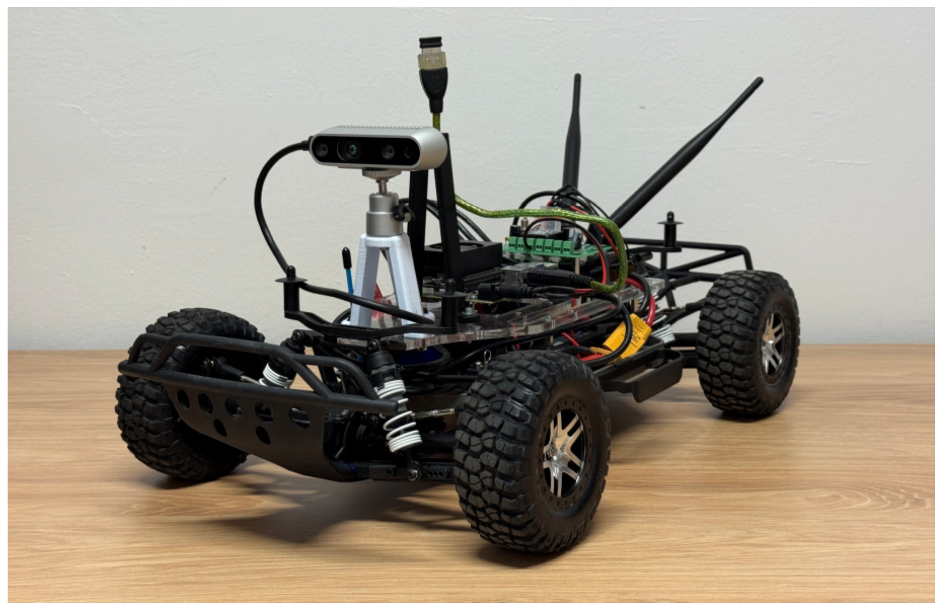
The major difference compared to the default recommendations lies in the environmental perception part. While the base setup contains a lidar sensor, we utilize an Intel RealSense D435i [10] camera module (Intel Corporation, Santa Clara, CA, USA), which is a compact and lightweight RGB-D sensor, combining stereo depth sensing with a global shutter RGB camera and an inertial measurement unit (IMU). One of its key advantages lies in the well-documented Intel RealSense SDK 2.28.1 (Intel Corporation, Santa Clara, CA, USA), which significantly reduces the development effort and facilitates rapid prototyping. The SDK supports multiple programming languages and provides out-of-box features involving real-time depth streaming, point cloud generation, and motion tracking. The camera module with the capable development environment provides a convenient platform for research areas, where rich visual information is crucial. For instance, object-detection-based navigation becomes feasible due to the availability of RGB images alongside the depth data. Moreover, the device enables scenario understanding and segmentation tasks in environments where texture, color, and object identity are essential for context-aware decisions. Figure 1 shows our proposed configuration.
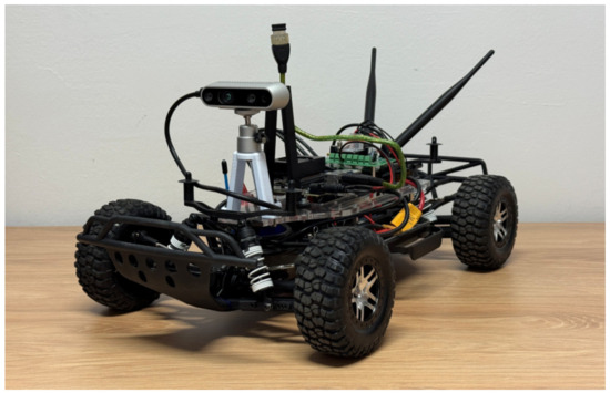
Figure 1.
Our build of the F1Tenth platform with the stereo camera module.
3.2. Software Environment
The primary objectives during the development of our software environment were modularity and reproducibility, therefore the entire software stack, encompassing sensor interfacing, data processing, and autonomous algorithms, is encapsulated within a Docker container. This containerized approach is configured to provide direct access to the essential peripherals, including hardware-accelerated computations, data streams of the camera system, and the actuators of the vehicle.
The various software components are integrated and communicate via Robot Operating System 2 (ROS 2). This framework not only ensures modular data flow between processes but also simplifies the remote user interaction. For enhanced operational flexibility, the vehicle also hosts its own Wi-Fi access point, allowing the platform to be deployed in diverse environments without the need for pre-existing static infrastructure. Therefore, external computers can connect directly to the vehicle’s network for teleoperation, data logging, and debugging purposes.
To facilitate reproducibility, all the setup and Docker related files are publicly available in our repository: https://github.com/farkas-peter/f1tenth_docker (accessed on 27 October 2025). It also contains a detailed description of the configuration and usage process.
3.3. Environmental Sensing and Control Functions
During the current phase of our work, we have been focusing on object detection-based navigation problems. Therefore, the autonomous software stack of the vehicle can be divided into three layers: object detection, object tracking, and vehicle control. This modular architecture enables the integration of different algorithms tailored to diverse environmental sensing or control tasks, involving goal reaching, path following, obstacle avoidance, or robust object representation.
Leveraging the high computational resources of the NVIDIA Jetson platform, the object detection can be performed via state-of-the-art solutions, like YOLO [11] or Faster R-CNN [12]. To achieve real-time performance, various inference acceleration techniques are available, including the conversion of models to formats like ONNX or TensorRT [13] to exploit hardware-specific capabilities. Such methods significantly improve runtime efficiency while maintaining accurate detection performance, enabling the system to reliably operate in real-time with an inference time of under 15 ms.
The stereo camera system enables the precise conversion of objects detected in image coordinates to their corresponding real-world 3D coordinates, which is a crucial step for reducing the simulation-to-reality gap. Each object is associated with a depth measurement, from which its 3D coordinates are determined using a projection function. The accurate real-world spatial information simplifies the operational domain for the object tracking and vehicle control layers.
Since object detection alone cannot provide a robust environmental representation, object tracking is also essential in such applications to ensure temporal and spatial consistency. In our proposed system, a Local Nearest Neighbor (LNN) data association has been implemented to track the detected objects among consecutive frames, then an n-out-of-m rule determines the initiations and terminations. These lightweight tracking modules help maintain persistent object identities over time, improving overall system reliability and stability in dynamic environments. Equation (1) shows the main formula of the LNN algorithm, while Equation (2) describes the track existence logic.
where xit represents object i at time t and zjt+1 denotes the detection at the next time step. Here, each object i is matched to the detection j that minimizes j* subject to the distance being below a τ gating threshold.
where m represents the number of last considered observations, n is the amount of required positive confirmations, and vi is a binary indicator, whether the given object was detected in the i-th frame.
Following the previous two layers, a robust list of environmental objects is available. This refined data serves as the primary input for the task-specific control layer, where problem specific features are extracted. Then, the actual control function can form the actuation signals based on this derived information. Such controllers can range from simple geometry-based solutions to more advanced learning-based techniques.
4. Evaluation
4.1. Experimental Setup
We have conducted an experimental validation of the proposed system through a real-world control problem. Traffic cones were selected to define the experimental environment, as they enable the construction of diverse scenarios such as goal reaching, obstacle avoidance, and trajectory tracking. Therefore, the object perception relies on a custom-trained YOLOv8 model (Ultralytics LLC, London, UK) for cone detection [14]. Table 1 introduces the major parameters of the utilized detector network.

Table 1.
Parameters of the utilized YOLOv8s cone detector network.
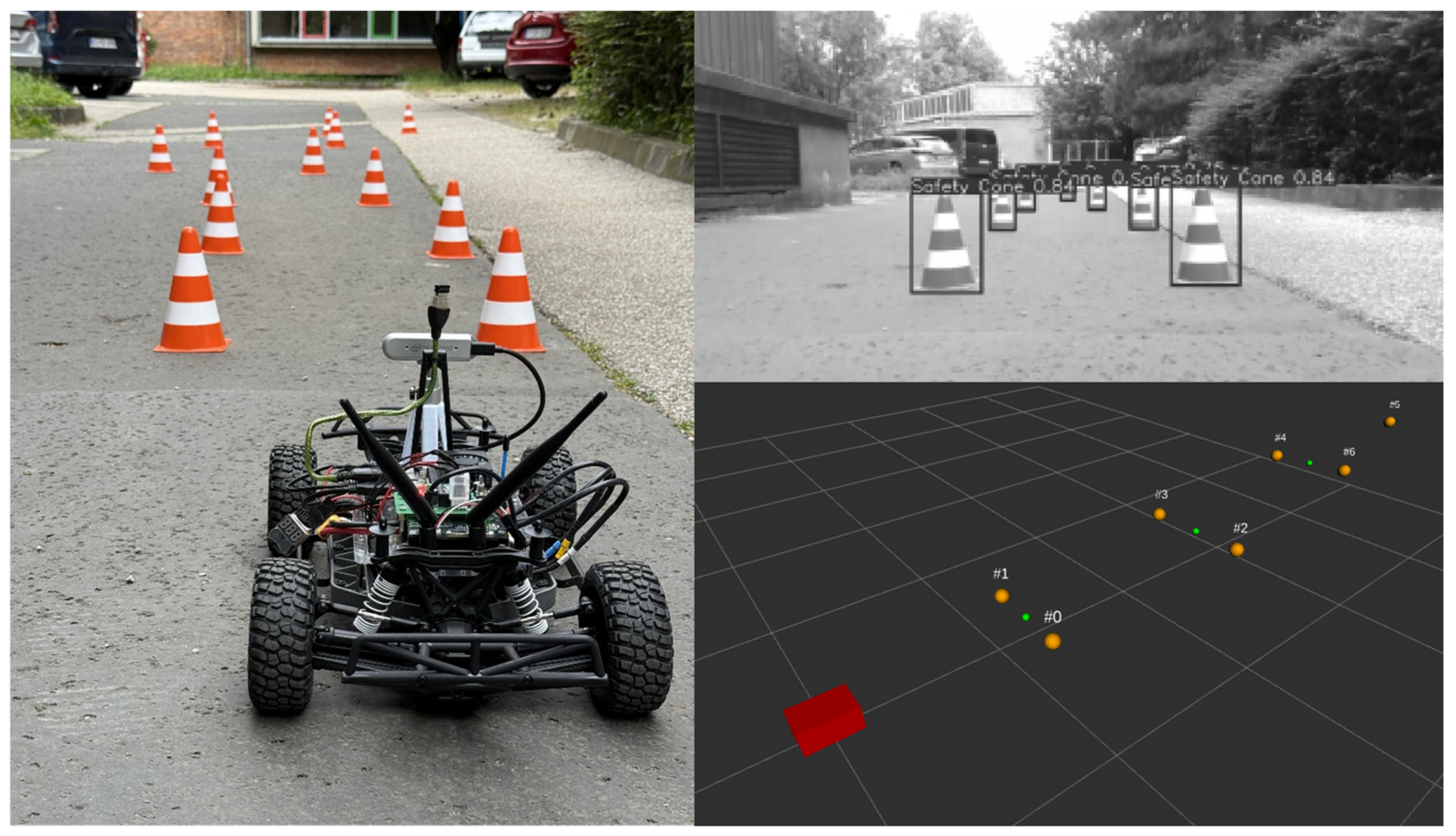
To extensively evaluate our system, the experimental setup requires the vehicle to autonomously navigate along trajectories defined by these cones. Figure 2 provides an example for the experimental setup and demonstrates the detection of the objects together with their representation in a real-world coordinate system.
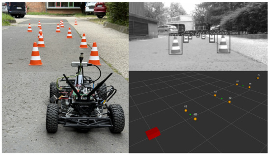
Figure 2.
An illustration of the experimental setup. On the left, an example scenario is visible, while on the right the object detection is demonstrated along with their representation in 3D coordinates (Red: ego vehicle; Orange: cones).
As the current phase of our research focuses on the system architecture and robust integration of the stereo camera system, we utilize a simple geometry-based Pure Pursuit controller to form the lateral actuation signals, while the longitudinal velocity was held constant across five predefined levels. Equation (3) demonstrates how the δ steering angle is calculated by the control function.
where L is the wheelbase of the vehicle, dlook is the look-ahead distance, and α is the angle between the heading of the vehicle and the look-ahead line.
4.2. Results
The performance of the developed software stack and integrated stereo camera system was validated through autonomous navigation experiments across diverse, cone-defined trajectories. The vehicle was tasked with navigating these paths at multiple, distinct velocity levels.
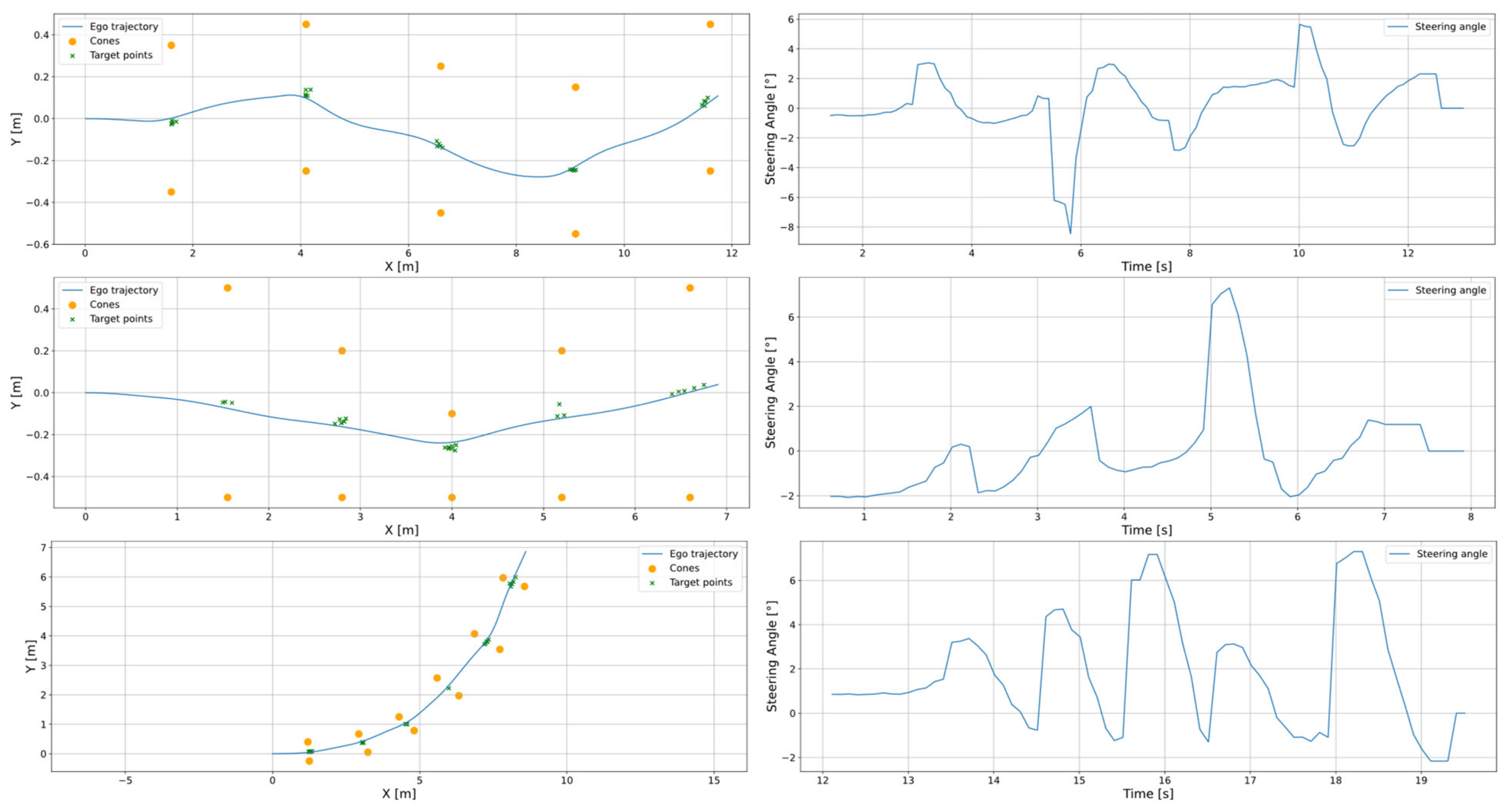
Figure 3 illustrates three example scenarios. The first setup involves navigating through a sinusoid path, the second scenario features gates with varying widths, while the third requires the vehicle to follow a sharper curve characterized by varying radius. The ego vehicle’s trajectory was computed onboard using the F1Tenth stack software module (University of Pennsylvania, Philadelphia, PA, USA). On the other hand, the cone positions were recorded during the real-world testing and serve as reference points for the trajectory data due to the lack of ground truth information.
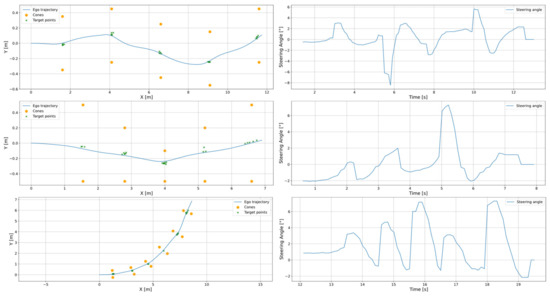
Figure 3.
Representative test scenarios. The left column depicts the odometry of the vehicle, while the right illustrates the evolution of the steering angle commands.
One can observe in Figure 3 that the system can successfully and accurately guide the vehicle through the central points of the gates in all the examined scenarios, achieving smooth and precise trajectories despite the diverse path geometries. Additionally, the figure depicts the steering angle demands across the scenarios. The curves illustrate stable and responsive steering behavior with smooth transitions that align with the changes in the path curvature. Furthermore, it is also notable that the maximum reference steering angle was around 7 degrees, which is only one-third of the vehicle’s maximum steering capability, thus reflecting effective actuator control.
The target points depicted in the figure were computed as the center points of the gates, determined by the detected cones. During the feature extraction, they are represented within the local coordinate system of the vehicle, then were transformed into the same coordinate frame as the odometry data to facilitate comparison. The inclusion of these target points aims to illustrate the accuracy of the environmental perception system. The trajectories indicate low deviations from the gate center points, typically limited to a few centimeters. Notably, the largest deviation can be observed near the end of the second trajectory, where the gate cones were positioned more than one meter from each other, placing them at the edge of the camera’s field of view. In such positions, the conversion to real-world coordinates can introduce greater measurement errors.
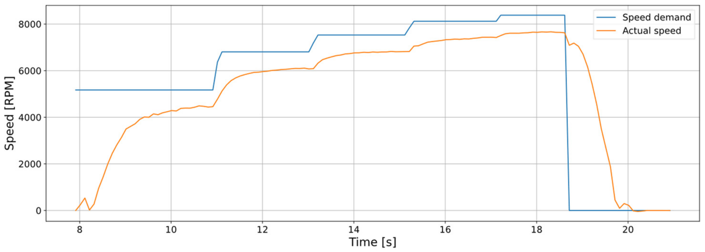
Figure 4 presents the comparison of the reference and realized motor speeds over time. To evaluate the open-loop velocity tracking performance of the system, the five pre-defined velocity levels were issued sequentially. The reference signal exhibits discrete step increases, each corresponding to a target rotational speed. The actual motor response follows each reference step with high consistency and low response time. During acceleration phases, the motor speed rises smoothly toward the reference level without overshooting, and steady-state tracking is achieved with only minor under-tracking. These small deviations are attributable to calibration process, where the wheels of the vehicle do not contact the ground, unlike the operational conditions. Toward the end of the sequence, a sharp drop in the speed command leads to a controlled deceleration of the motor, demonstrating the system’s ability to follow descending commands without oscillation. Overall, these results confirm that the longitudinal velocity control system is capable of reliably tracking reference speeds.
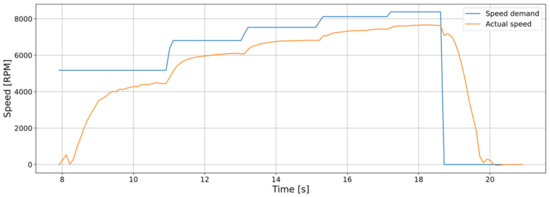
Figure 4.
Comparison between the reference and realized motor speed profiles of the ego vehicle across the five distinct pre-defined velocity levels.
In these real-world scenarios, the system consistently achieved successful track completion. Stable vehicle operation was maintained across all tested speeds, from lower to higher velocity levels, underscoring the system’s capability to reliably process stereo vision data and handle the actuators. The average position error of the real-world object representation was below 3 cm. These results highlight the effective integration of the environmental perception modules and the robustness of the software interfaces. The experiments demonstrate that our system implements a reliable and stable vision-based platform, suitable for conducting real-world evaluation and validation of autonomous driving research.
5. Discussion
During our research, we implemented a stereo vision system on the F1Tenth platform. The default configuration includes a 2D lidar sensor, while other setups often incorporate monocular camera systems. This section discusses the main differences between such solutions and introduces our motivation behind the stereo vision system.
Lidars typically offer less computational need and more accurate distance measurement across a wider field of view. Therefore, they are efficient for trajectory following or obstacle avoidance tasks but may not be suitable for applications requiring high-level semantic understanding or dense scene interpretation. Conversely, monocular cameras enable vision-based tasks to be carried out and involve a modest computational load, but they face significant challenges in accurately mapping detected objects to real-world coordinates.
Although stereo vision systems are typically more computationally intensive, in our application most of these extra processes are performed inside the camera module, thus not impacting the onboard computational capacity of the vehicle. We chose to adopt stereo vision in light of the above considerations together with the primary objective of our research to facilitate complex visual data-driven tasks such as scenario understanding or vision-based decision making. Nonetheless, it is also important to mention that such solutions inherently introduce specific limitations compared to lidar-based systems, notably sensitivity to lighting conditions, increased latency in complex environments, and potential optical distortions impacting precise distance measurements.
6. Conclusions
In this work, we presented a modular software architecture for the F1Tenth platform, successfully integrating an Intel RealSense D435i stereo camera for enhanced environmental perception. Our system is encapsulated within a publicly available Docker environment and utilizes ROS 2 for inter-component communication. The developed framework facilitates real-time object detection, tracking, and 3D localization, while also providing clear interfaces for the actuators.
Experimental validation has been carried out, where the proposed setup was faced with a real-world cone-based trajectory following task to demonstrate the effectiveness of the perception pipeline. The reliable performance of the system underscores the potential of stereo vision systems to serve as the primary sensing modality in F1Tenth applications.
Our future work will focus on exploring more complex control strategies (e.g., the real-world deployment of reinforcement learning agents) and leveraging the rich data of the stereo camera system for advanced scenario understanding tasks.
Author Contributions
Conceptualization, P.F., B.T. and S.A.; methodology, P.F., B.T. and S.A.; software, P.F. and B.T.; validation, P.F., B.T. and S.A.; writing P.F., B.T. and S.A.; supervision, S.A. All authors have read and agreed to the published version of the manuscript.
Funding
Project no. KDP-IKT-2023-900-I1-00000957/0000003 has been implemented with the support provided by the Ministry of Culture and Innovation of Hungary from the National Research, Development and Innovation Fund, financed under the KDP-2023 funding scheme.
Institutional Review Board Statement
Not applicable.
Informed Consent Statement
Not applicable.
Data Availability Statement
Data is available on request from the authors.
Conflicts of Interest
The authors declare no conflicts of interest.
References
- RoboRacer Foundation. RoboRacer. Available online: https://roboracer.ai (accessed on 16 May 2025).
- Nguyen, S.; Rahman, Z.; Morris, B. Pedestrian emergency braking in ten weeks. In Proceedings of the International Conference on Vehicle Electronics and Safety 2022, Bogota, Colombia, 14–16 November 2022. [Google Scholar]
- Jeong, Y. Interactive lane keeping system for autonomous vehicles using LSTM-RNN considering driving environments. Sensors 2022, 22, 9889. [Google Scholar] [CrossRef] [PubMed]
- Hell, M.; Hajgató, G.; Bogár-N, Á.; Bári, G. A LiDAR-based approach to autonomous racing with model-free reinforcement learning. In Proceedings of the 2024 IEEE Intelligent Vehicles Symposium (IV), Jeju Island, Republic of Korea, 2–5 June 2024; pp. 258–263. [Google Scholar]
- Michael, B.; Rita, T.; Giovanni, P. Train in Austria, race in Montecarlo: Generalized RL for cross-track F1tenth LiDAR-based races. In Proceedings of the 2022 IEEE 19th Annual Consumer Communications & Networking Conference (CCNC), Las Vegas, NV, USA, 8–11 January 2022; pp. 290–298. [Google Scholar]
- Benjamin, D.E.; Raphael, T.; Macro, C.; Felix, J.; Johannes, B.; Hendrik, W.J.; Herman, A. Unifying F1TENTH autonomous racing: Survey, methods and benchmarks. arXiv 2024, arXiv:2402.18558. [Google Scholar] [CrossRef]
- Meraj, M. End-to-end LiDAR-driven reinforcement learning for autonomous racing. arXiv 2023, arXiv:2309.00296. [Google Scholar]
- Jiancheng, Z.; Hans-Wolfgang, L. F1TENTH: An overtaking algorithm using machine learning. In Proceedings of the 2023 28th International Conference on Automation and Computing (ICAC), Birmingham, UK, 30 August–1 September 2023; pp. 1–6. [Google Scholar]
- Kyle, S.; Arjun, B.; Dhruv, S.; Ilya, K.; Sergey, L. FastRLAP: A system for learning high-speed driving via deep RL and autonomous practicing. arXiv 2023, arXiv:2304.09831. [Google Scholar]
- Intel. Intel RealSense Depth Camera D435i. Available online: https://www.intelrealsense.com/depth-camera-d435i/ (accessed on 15 May 2025).
- Ultralytics. Ultralytics YOLO1. Available online: https://docs.ultralytics.com/models/yolo11/ (accessed on 15 May 2025).
- Girshick, R. Fast R-CNN. In Proceedings of the IEEE International Conference on Computer Vision (ICCV), Santiago, Chile, 7–13 December 2015; pp. 1440–1448. [Google Scholar]
- Ultralytics. Quick Start Guide: NVIDIA Jetson with Ultralytics YOLO11. Available online: https://docs.ultralytics.com/guides/nvidia-jetson/ (accessed on 10 May 2025).
- Muhammad, A. Safety Cone Detection. Available online: https://github.com/EngrAwab/Safety_Cone_detection (accessed on 22 May 2025).
Disclaimer/Publisher’s Note: The statements, opinions and data contained in all publications are solely those of the individual author(s) and contributor(s) and not of MDPI and/or the editor(s). MDPI and/or the editor(s) disclaim responsibility for any injury to people or property resulting from any ideas, methods, instructions or products referred to in the content. |
© 2025 by the authors. Licensee MDPI, Basel, Switzerland. This article is an open access article distributed under the terms and conditions of the Creative Commons Attribution (CC BY) license (https://creativecommons.org/licenses/by/4.0/).

