Proceeding Paper

Phase-Field Simulation of Bubble Evolution and Heat Transfer in Microchannels Under Subcooled and Saturated Flow Boiling †

School of Energy and Power Engineering, Dalian University of Technology, Dalian 116024, China
*
Author to whom correspondence should be addressed.
Presented at the 5th International Conference on Advances in Mechanical Engineering (ICAME-25), Islamabad, Pakistan, 26 August 2025.
Eng. Proc. 2025, 111(1), 27; https://doi.org/10.3390/engproc2025111027
Published: 28 October 2025

Abstract

This study numerically investigates the growth and dynamics of a single vapor bubble in a rectangular microchannel under subcooled and saturated inlet conditions using the phase-field method coupled with the Lee phase-change model. Results demonstrate that subcooled flow induces early bubble nucleation, pronounced lateral expansion along the heated wall, and prolonged bubble-wall contact due to stronger condensation at the interface and thinner microlayer formation. Enhanced recirculating vortices and steeper thermal gradients promote vigorous evaporation and increased local heat flux, resulting in faster downstream bubble propagation driven by significant axial pressure gradients. Analysis of temperature gradient and heat flux profiles confirms that subcooled conditions produce higher wall heat flux and more frequent peaks in evaporative flux compared to the saturated case, indicating intensified phase-change activity and thermal transport. Conversely, saturated conditions produce more spherical bubbles with dominant vertical growth, weaker condensation, and symmetrical thermal and pressure fields, leading to slower growth and delayed detachment near the nucleation site. These findings highlight the critical influence of inlet subcooling on bubble morphology, flow structures, heat transfer, and pressure distribution, underscoring the thermal management advantages of subcooled boiling in microchannel applications.

1. Introduction

Flow boiling in microchannels has gained significant attention due to its high heat transfer efficiency, compact size, and the ability to harness latent heat during phase change. While saturated boiling produces more intense vapor formation but presents problems such as flow instability and critical heat flux, subcooled boiling improves heat transmission by starting early nucleation while reducing vapor accumulation. In contrast to conventional-scale boiling, flow boiling in microchannels exhibits distinct phenomena such as limited bubble growth and pronounced surface tension effects. Although experiments offer valuable insights, they often struggle to capture the rapid, microscale phase-change phenomena. Numerical simulations—especially those utilizing the phase-field method coupled with phase-change models such as the Lee model—provide a powerful alternative for exploring interface dynamics, heat transfer, and bubble behavior under both subcooled and saturated conditions. Because of its significance in thermal management for high-heat-flux systems, flow boiling in microchannels has been thoroughly investigated. The study Wu et al. [1] carried out a thorough numerical analysis of subcooled boiling in small rectangular channels, identifying transitions from bubbly to churn flow regimes under increasing heat flux, and proposing a new dimensionless parameter for regime classification. They did this by combining Lee’s model with VOF to capture heat flux-induced bubble dynamics. Luo and Li [2] demonstrated good temperature prediction accuracy with errors ranging from ± 5 % to 20% through simulations of subcooled boiling in manifold microchannel heat sinks, validating both Lee’s model and the interfacial resistance technique against experimental data. In order to clarify the impact of film thickness and capillary number on heat transfer, particularly under low-superheat conditions, Okajima and Stephan [3] concentrated on vapor bubble expansion and liquid film properties in a 200 μm microchannel. By combining the VOF method with conjugate heat transfer, a recent study demonstrated the influence of channel aspect ratio on substrate temperature distributions and bubble-driven Nusselt numbers in saturated boiling within non-circular microchannels [4]. The study by Rajkotwala et al. [5] demonstrated the importance of thin-film evaporation in improving wall heat transmission in comparison to conventional channels by using local front reconstruction (LS) and VOF techniques for bubble nucleation in microchannels. It was demonstrated that when estimating wall temperature and flow regimes under subcooled conditions, methods such as VOF and Eulerian thermal phase change frequently perform better than traditional models [6]. In order to account for shear-induced film thinning and capture several boiling zones (liquid slug, partially contained bubbles, and film breakdown), the study by Jain et al. [7] created a 1D mechanistic model for pressure drop and heat transmission in rectangular microchannels. This study supports a number of CFD boiling model assumptions. The study by Roccon [8] introduced a phase-field-based boiling simulation framework that can be used for microchannel scales and has been validated on traditional benchmarks (such as the Stefan issue and bubble growth). Their approach effectively captures the evolution of phase interfaces without the need for explicit geometry reconstruction.
In a 200 μm microchannel, the study by Mukherjee and Kandlikar [9] carried out a thorough numerical simulation of vapor bubble formation and related wall heat transfer. They demonstrated that bubble growth changes from spherical to elongated plug regimes using a level–set interface tracking with SIMPLER-based Navier–Stokes. This traps a liquid film and greatly increases wall heat flow when wall superheat rises, primarily as a result of microlayer evaporation. The development of thin liquid films and flow instabilities—phenomena that were well captured by the phase-field and VOF models—as well as high-speed photographic proof of flow boiling in parallel water-cooled microchannels were shown [10]. Basic features of microchannel flow boiling, such as flow patterns, CHF, and heat transfer mechanisms, were compiled. These showed that subcooled and saturated boiling regimes in hydraulic diameters smaller than 300 μm have unique microscale behaviors that call for high-fidelity numerical models [11]. Phase-field-based CFD demonstrated that conjugate heat transfer (inside the solid substrate) significantly influences wall heat transfer and bubble formation, particularly when wall thickness or material varies. This suggests that coupling solid–fluid heat conduction is crucial for simulation accuracy [12]. The study by Mukherjee et al. [13] used level–set CFD simulations that were verified against tests to offer a thorough examination of bubble dynamics and wall heat transfer. They found that surface tension and liquid flow rate have no effect on heat flux, but wall superheat enhances it. The bubbly, slug, and contact-slug boiling flow pattern transitions in horizontal microchannels and showed how channel constriction and mass flux affect film evaporation and total heat transfer efficiency was replicated [14]. A theoretical model for evaporative heat transfer fueled by an inflating bubble in a microchannel was created by the study [15]. Their research demonstrates how bubble expansion and microlayer dynamics directly affect heat transfer rates in subcooled environments. In trials with subcooled water in rectangular microchannels, the research study by Suzuki et al. [16] found that microbubble emission boiling (mEB) occurred often, especially at high subcooling and flow rates. Despite extensive studies on subcooled and saturated boiling in microchannels, accurately capturing microscale phase-change dynamics and heat transfer remains challenging. This study addresses these gaps using COMSOL Multiphysics version 6.1 with a phase-field method coupled with the Lee model, incorporating conjugate heat transfer to resolve temperature gradients and local heat flux. Uniquely, it systematically compares subcooled and saturated conditions within a unified framework, providing new insights into bubble behavior, flow structures, and pressure evolution for thermal management applications.

2. Numerical Model

In this study, we employ a two-dimensional computational model of a rectangular microchannel (width W = 1000 μm, height H = 200 μm to investigate flow boiling under both saturated ( 373.15 K ) and subcooled ( 370.15 K ) inlet conditions, as shown in Figure 1. The governing equations include the incompressible Navier–Stokes equations with gravity, a non-conservative convective phase-field equation for interface tracking, and an energy equation augmented by the Lee phase-change source term. The bottom wall is held at a constant temperature of 378.15 K to drive nucleation, and a bubble seed of radius 20 μm is initialized at x = 140 μm from the inlet. Boundary conditions comprise a uniform inlet velocity of 0.1 m / s , zero pressure at the outlet, and no-slip on all walls. We discretize using a fine, structured mesh refined near the interface region and solve with a fully coupled, implicit time-stepping solver. Key parameters are summarized in Table 1 and the physical properties used in simulation are shown in Table 2.
Navier–Stokes Equation (Laminar Flow with Gravity) [17,18]
ρ ( ϕ ) u t + u · u = p + · μ ( ϕ ) u + ( u ) T + ρ ( ϕ ) g + F σ
where u is the velocity vector, p is pressure, ρ ( ϕ ) and μ ( ϕ ) are the phase-dependent density and viscosity, g is gravitational acceleration, and F σ represents the surface tension force derived from the chemical potential gradient in the phase-field method.
Property Interpolation [19,20]
ρ ( ϕ ) = 1 + ϕ 2 ρ v + 1 ϕ 2 ρ l
μ ( ϕ ) = 1 + ϕ 2 μ v + 1 ϕ 2 μ l
k ( ϕ ) = 1 + ϕ 2 k v + 1 ϕ 2 k l
These equations interpolate fluid properties (density ρ and viscosity μ ) between liquid ( ϕ = 1 ) and vapor ( ϕ = + 1 ) phases based on the phase-field variable ϕ .
Continuity Equation [21,22]
· u = m ˙ ρ
This equation ensures mass conservation, accounting for a non-zero mass source term m ˙ due to evaporation or condensation.
Phase-Field Equation (Non-Conservative, Convective Form) [17,23]
τ ϕ t + u · ϕ = λ 2 ϕ 1 λ f ( ϕ )
ϕ is the phase-field variable distinguishing vapor and liquid phases, τ is a relaxation parameter, λ controls interface thickness, and f ( ϕ ) is the derivative of the double-well free energy.
Free Energy Potential and Its Derivative [24]
f ( ϕ ) = 1 4 ( ϕ 2 1 ) 2 , f ( ϕ ) = ϕ ( ϕ 2 1 )
This potential function ensures two stable phases at ϕ = ± 1 , enabling diffuse interface representation between phases.
Energy Equation with Phase-Change Source [22,25]
ρ ( ϕ ) c p ( ϕ ) T t + u · T = · k ( ϕ ) T + m ˙ h f g
This equation describes energy transport including convection, conduction, and latent heat addition due to phase change. Here, T is temperature, c p is specific heat, k is thermal conductivity, and h f g is latent heat of vaporization.
Phase-Change Rate (Lee Model) [21,26]
m ˙ = M · T T sat T sat · H ( ϕ )
m ˙ is the phase-change mass flux, M is the Lee model coefficient controlling the rate, T sat is the saturation temperature, and H ( ϕ ) is a smoothed Heaviside function.
Smoothed Heaviside Function [27]
H ( ϕ ) = 1 2 1 + tanh ϕ δ
δ is a smoothing parameter that determines the interface sharpness between liquid and vapor in the phase field.
Wettability Boundary Condition (Contact Angle) [28,29]
n · ϕ = 2 λ cos ( θ ) · n ^ w
This Neumann-type boundary condition controls wettability, where θ is the contact angle (e.g., 30 ° ), λ is interface thickness, and n ^ w is the normal to the wall. This enforces the specified contact angle between the phase interface and solid surface.
Boundary Conditions
  • Inlet (x = 0):
    u = ( 0.1 m / s , 0 ) , T inlet = 370.15 K ( subcooled ) 373.15 K ( saturated ) , ϕ = 1
  • Bottom Wall:
    T = 378.15 K , u = 0
  • Outlet (x = 1000 μm):
    p = 0 , Convective flux for T and ϕ
  • Initial Bubble Seed: [17,19]
    ϕ ( x , y , t = 0 ) = tanh r ( x , y ) R 0 2 λ
    where R 0 = 20 μm is the initial bubble radius, and the bubble is centered at x = 140 μm from the inlet.

Mesh Independence Study

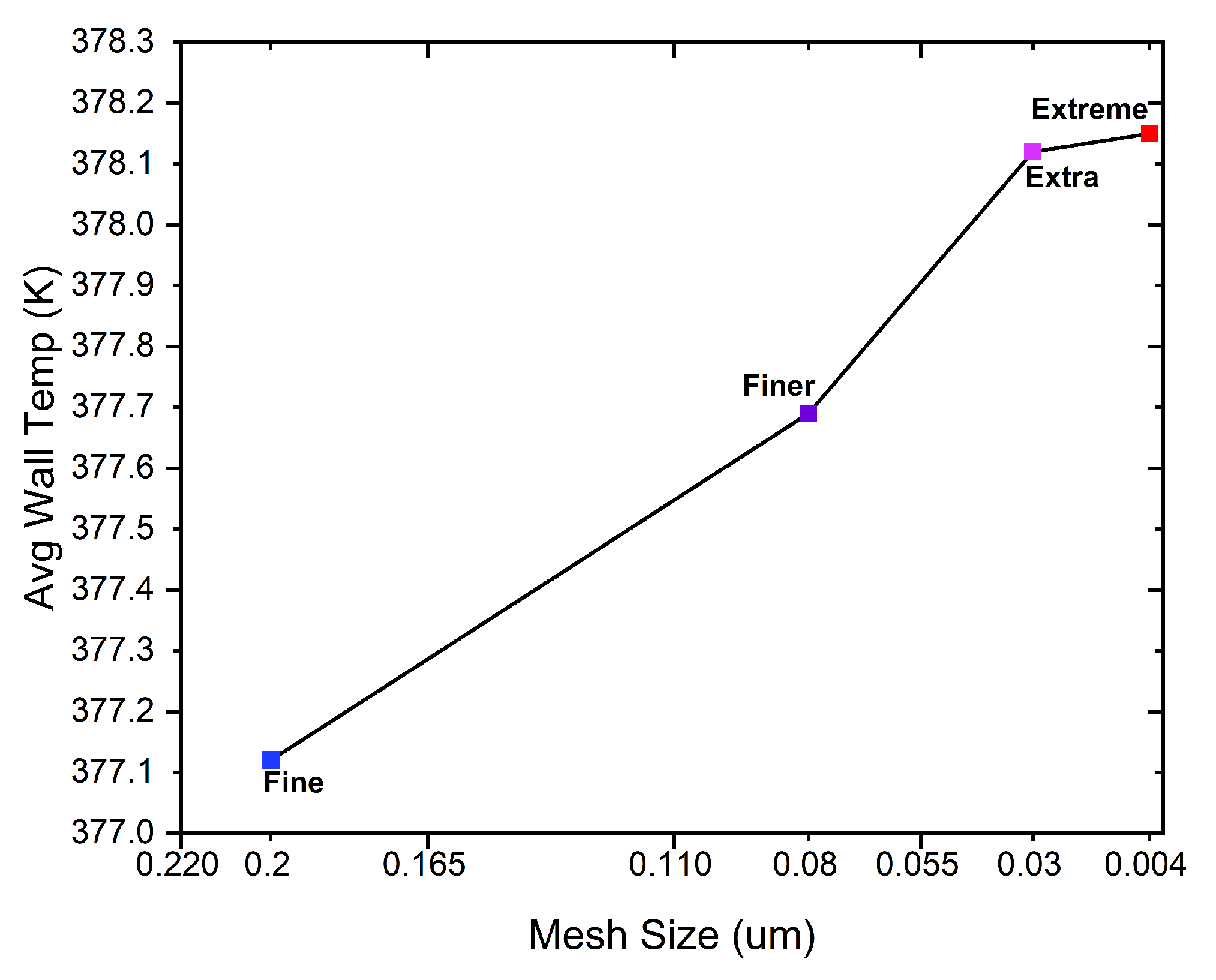
To ensure numerical accuracy and computational efficiency, a mesh sensitivity analysis was conducted for the two-dimensional rectangular microchannel under both subcooled and saturated boiling conditions. With a total of 37 , 649 mesh vertices, the mesh is made up of 74 , 372 triangular elements, 948 edge elements, and 8 vertex elements. The area of the entire computational domain is around 2.0 × 10 7 m 2 . The skewness measure was used to assess the quality of the mesh. High overall mesh regularity appropriate for multiphase interface resolution was indicated by the average element quality of 0.9637 and the minimum element quality of 0.6733 . The mesh size gradation from bulk fluid areas to near the bubble boundary was suitable, as indicated by the element area ratio of 0.2076 . Figure 2 shows the variation in average wall temperature as a function of mesh size, where four different mesh levels like Fine, Finer, Extra, and Extreme were tested. As the mesh size decreases, the average wall temperature increases and gradually converges. The temperature stabilizes between the extra and Extreme mesh levels, indicating that further refinement yields negligible change. This confirms that the extra mesh provides a mesh-independent solution, while avoiding the high computational cost associated with the extreme mesh.
This study establishes that the selected mesh level ensures accurate resolution of thermal boundary layers, bubble interfaces, and local heat transfer characteristics without incurring excessive simulation time. Hence, the Extra mesh was adopted for all subsequent simulations presented in this work.

3. Results and Discussion

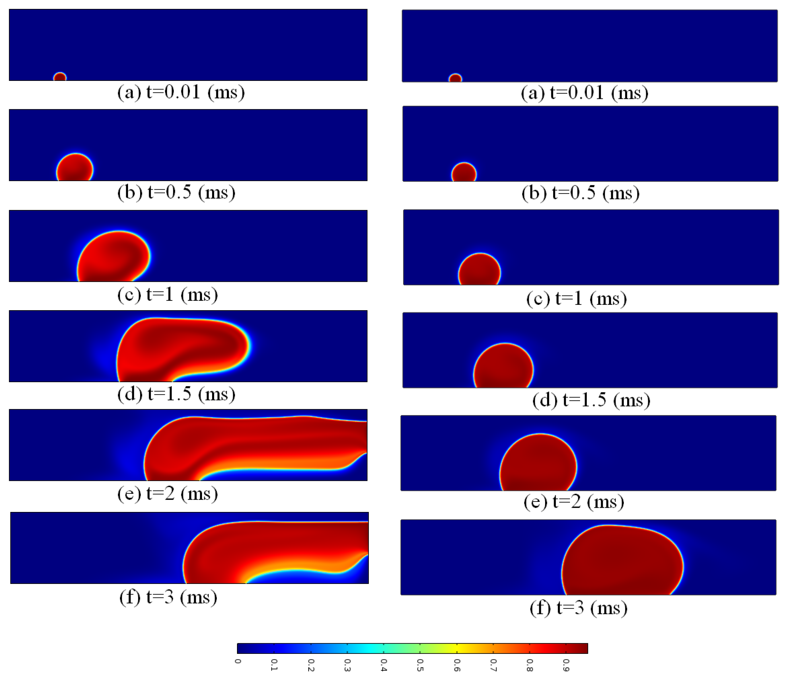
The governing Navier–Stokes, energy, and phase-field equations are discretized using the finite element method. A segregated solution approach solves momentum, continuity, energy, and phase-field equations sequentially each time step. Phase change is modeled via the Lee source term, with fluid properties interpolated based on the phase field. The numerical simulation initiates with bubble nucleation occurring at x = 140 μm near the inlet of the microchannel, which has a length of 1000 μm. At the initial stage, the bubble maintains an almost spherical shape due to uniform surface tension forces acting isotropically. Over time, the bubble grows as evaporation takes place at the vapor–liquid interface, fueled by thermal energy supplied from the heated wall. As the bubble volume increases and nears the width of the channel, confinement effects become important, causing the bubble to elongate along the flow direction. Meanwhile, the inlet flow imposes hydrodynamic forces on the bubble, driving it axially downstream. This advection is especially noticeable under subcooled inlet conditions, where condensation at the rear of the bubble generates a pressure difference that further pushes the bubble forward. These findings are in good agreement with previous studies [30], thereby validating the accuracy of the present numerical model. The combined effects of volume expansion from evaporation and flow-induced transport result in the bubble stretching along the channel length. At later stages, the bubble occupies a significant portion of the channel’s cross-sectional area and exhibits more complex interactions with the surrounding flow and thermal fields. This dynamic is more evident in subcooled conditions, where a stronger temperature gradient between the wall and liquid increases evaporation at the bubble front and condensation at the rear, thereby intensifying its downstream movement. Conversely, in saturated conditions, the weaker thermal gradient limits the bubble’s movement, keeping it closer to the nucleation site. The time-evolution of the vapor volume fraction during bubble growth in the rectangular microchannel for both subcooled and saturated inlet conditions is depicted in Figure 3. The bubble first emerges in the subcooled scenario (left column), but because of stronger condensation effects, it spreads laterally along the heated wall. The vapor condenses more quickly at the interface due to the lower inlet temperature (370.15 K), delaying vertical expansion and producing a thinner microlayer underneath the bubble which agrees with this study [1]. The bubble keeps stretching horizontally and stays in touch with the heated surface for a longer period of time than in the saturated state as time increases from t = 0.5 ms to t = 3 ms. The saturated inlet scenario (right column), on the other hand, has a more spherical bubble shape with quicker upward rise. Vapor accumulation predominates and the bubble detaches more readily with less condensation at the interface because of decreased subcooling (373.15 K). The comparison shows that subcooling has a major impact on bubble form and microlayer evaporation, resulting in different development trajectories and heat transfer properties between the two scenarios.
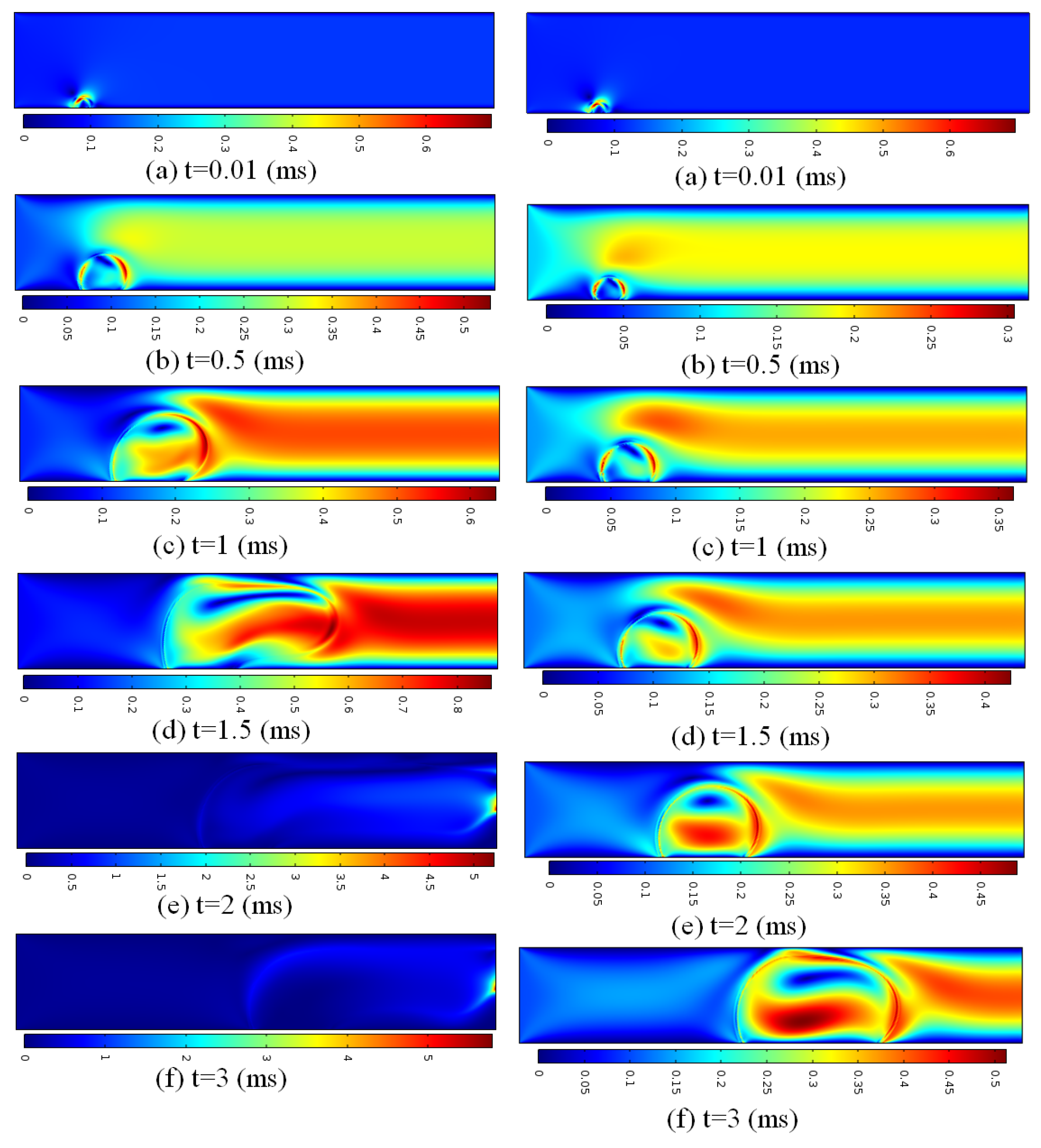
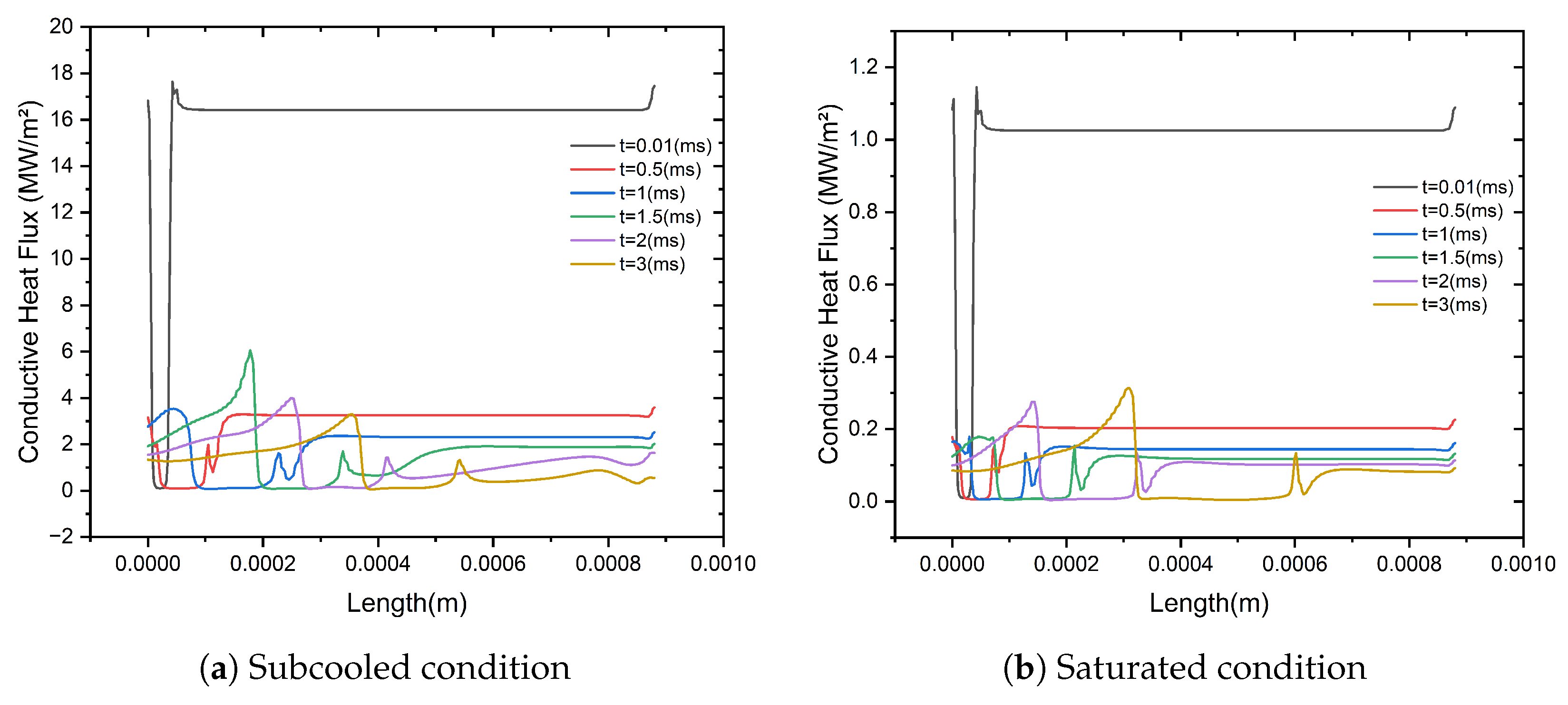
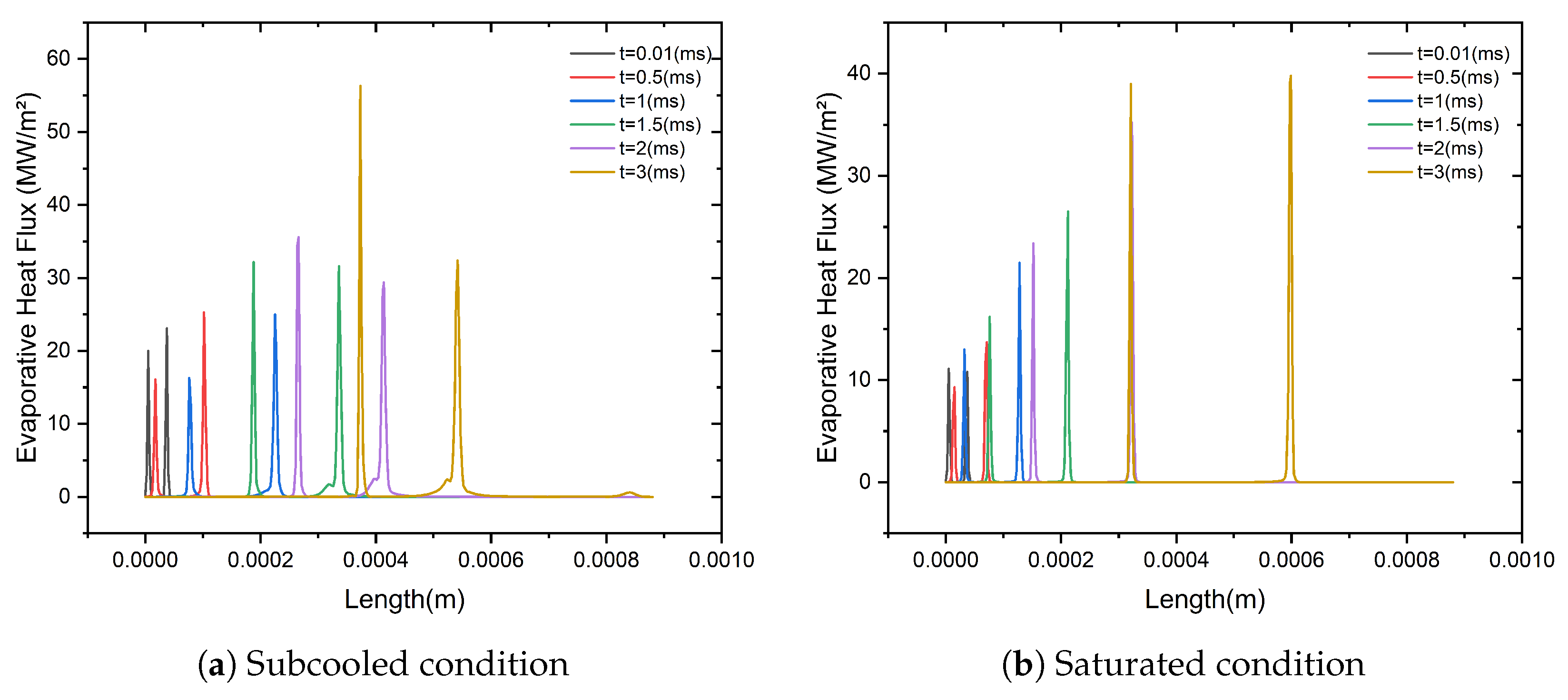
The velocity contours in the microchannel at various time instances for both subcooled and saturated intake conditions are shown in Figure 4. In both situations, flow acceleration is seen close to the nucleating bubble at early times ( t = 0.5 ms). However, because of increased condensation and the ensuing pressure differential across the interface, stronger lateral and downward flow is seen around the bubble interface in the subcooled condition. The formation of vortical structures starts from t = 1 ms and beyond. Improved recirculation zones adjacent to the bubble front in the subcooled flow (left column) serve to restrict the bubble closer to the wall and encourage spreading. The larger temperature differential between the heated surface and the cooler input fluid causes thermocapillary and buoyancy-induced motions, which in turn causes these consequences. On the other hand, because buoyancy forces outweigh condensation effects, the saturated scenario (right column) exhibits more noticeable vertical flow along the bubble’s wake. Early bubble lift-off results from the flow profile becoming more upward-directed over time. This demonstrates how different thermal boundary conditions at the inlet cause variations in fluid momentum and interface dynamics. The temperature distribution in the rectangular microchannel is shown changing over time for both saturated and subcooled inlet conditions in Figure 5. In both situations, the bottom wall temperature is maintained at 378.15 K. The subcooled inlet case at 370.15 K is shown on the left column, whereas the saturated inlet at 373.15 K is displayed in the right column. In the subcooled scenario, the bubble initiates earlier and propagates rapidly downstream. The high-temperature zone, represented in yellow and light orange, follows the advancing bubble interface. A steep thermal gradient near the bubble–liquid interface, especially at the front and bottom sides, indicates intense local evaporation and energy exchange. Due to the cooler incoming liquid, enhanced heat transfer from the heated wall is observed, maintaining a distinct subcooled thermal boundary layer throughout the simulation which agrees well the findings of this study [12]. In contrast, the saturated condition displays a slower bubble growth rate and a more localized temperature rise near the nucleation site. Since the temperature difference between the wall and saturated fluid is relatively small, the thermal field remains more symmetric, and heat is confined around the bubble. The bubble stays pinned near the initial nucleation location, with the thermal layer spreading more uniformly. By t = 3 ms, the bubble in the subcooled case covers a larger portion of the channel and leaves a pronounced trailing region of lower temperature. Meanwhile, in the saturated case, the bubble grows more gradually, and the temperature field remains centered around it. These observations highlight the superior heat transfer performance under subcooled conditions, attributed to stronger thermal gradients and larger wall-to-liquid temperature differences. The pressure distribution in the rectangular microchannel at various time steps is shown in Figure 6, which contrasts the situations of a saturated inlet at 373.15 K with a subcooled inlet at 370.15 K. After nucleating under subcooled conditions, the bubble quickly moves downstream in an elongated shape, almost reaching the channel outlet at t = 3 ms. The saturated inlet situation, on the other hand, results in slower and more limited bubble growth close to the nucleation site, with the bubble remaining near the channel’s center. The variation in thermal driving power is the main cause of this discrepancy. A higher degree of superheat between the subcooled liquid and the heated wall promotes strong vapor formation at the front of the bubble and condensation at the rear. This imbalance generates an axial pressure gradient that pushes the bubble forward along the channel matching the findings of this study [31]. Under subcooled conditions, the pressure contour clearly exhibits a more intense and concentrated high-pressure zone, consistent with rapid bubble growth and transient phase-change behavior. In contrast, the saturated case presents more symmetric temperature conditions around the bubble, resulting in a lower pressure gradient. As a result, the bubble tends to grow in place rather than move downstream, remaining pinned near the nucleation site while expanding more slowly. The temperature gradient T is displayed in Figure 7 for times between t = 0.01 ms and t = 3 ms. The temperature gradient represents the spatial rate of change of temperature along the microchannel. It quantifies how rapidly the temperature varies at different points along the flow direction. The gradient progressively flattens downstream after reaching a sharp peak close to the channel intake when subcooled. Early on, this trend is more noticeable (e.g., t = 0.01 ms and t = 0.5 ms), indicating that there is a significant temperature differential between the heated wall (378.15 K) and the entering colder liquid (370.15 K). Intense local boiling and quick energy absorption are shown by the sharp increase in T close to the nucleation site. On the other hand, because of a smaller inlet-to-wall temperature differential (373.15 K at inlet), the saturated scenario exhibits a gentler gradient close to the wall. A faster flattening of the profile indicates a more even dispersion of heat. Interestingly, both circumstances exhibit reduced gradient peaks as time increases (especially at t = 2 ms and t = 3 ms), which is indicative of expanded vapor bubbles filling the heated surface and partially insulating it from the liquid. The conductive heat flux distribution down the microchannel is depicted in Figure 8. Higher flux peaks are observed early on in the subcooled scenario, peaking at t = 0.01 ms and approaching 20 kW/m2. This indicates quick energy transfer into the liquid close to the heated surface and is consistent with the previously noted high-temperature gradient. The conductive heat flux becomes more dispersed and varies downstream as the vapor bubble expands and spreads laterally, especially at t = 1.5 ms and t = 3 ms. Conductive heat exchange is improved in the subcooled case due to the broader microlayer and longer wall contact time. The saturated scenario, in contrast, displays less variation and lower peak heat fluxes (up to 12 kW/m2), which is consistent with more localized vapor development and less interface motion. The latent heat transfer caused by phase shift is quantified by the evaporative heat flux profiles in Figure 9. Evaporative heat flux spikes are confined and mostly occur where bubble formation is most active or where the phase interface is steepest. These spikes are more frequent and intense under subcooled conditions, especially from t = 1 ms onward. More frequent evaporation bursts and increased energy absorption are caused by the stronger subcooling, which also causes more violent cycles of condensation and vapor regeneration. The flux spikes are more limited and less frequent for the saturated inlet. The evaporative energy contribution is smoother but less severe since the bubble expands continuously without experiencing sudden condensation–revaporization processes. This discrepancy demonstrates how inlet subcooling raises microlayer activity and phase-change intensity, both of which greatly improve total heat transfer performance.

4. Conclusions

This study numerically investigated single vapor bubble dynamics in a rectangular microchannel under subcooled and saturated inlet conditions using the phase-field method coupled with the Lee phase-change model. Results show that subcooled conditions promote early nucleation, lateral bubble growth along the heated wall, and prolonged wall contact due to strong condensation at the interface. This leads to enhanced recirculating flow, steeper temperature gradients, higher local heat flux, and stronger axial pressure gradients that accelerate bubble motion.The thermal analysis further reveals that under subcooled conditions, the temperature gradient and conductive heat flux are significantly higher near the heated wall compared to the saturated case, indicating stronger thermal transport. Additionally, the subcooled scenario exhibits sharper and more frequent peaks in evaporative heat flux, correlating with active phase-change zones and bubble interface movement. In contrast, saturated conditions produce more spherical bubbles with faster vertical growth, weaker condensation, and reduced hydrodynamic effects, resulting in slower bubble detachment and growth. The thermal and heat flux distributions under saturation remain smoother and more localized, indicating lower overall phase-change intensity.In summary, subcooled inlet conditions enhance phase-change dynamics, promote prolonged wall contact, and create stronger hydrodynamic and thermal effects compared to saturated conditions. This leads to improved thermal transport performance and more active bubble movement, making subcooled boiling favorable for microchannel-based thermal management systems such as compact evaporators, heat sinks, and U-tube steam generators.

Author Contributions

Conceptualization, methodology, software, validation, formal analysis, and investigation, J.A.J. and Resources and supervision, Y.H. All authors have read and agreed to the published version of the manuscript.

Funding

This research received no external funding.

Institutional Review Board Statement

Not applicable.

Informed Consent Statement

Not applicable.

Data Availability Statement

The data that support the findings of this study are available from the corresponding author upon reasonable request.

Acknowledgments

The authors would like to acknowledge the support provided by the School of Energy and Power Engineering, Dalian University of Technology, Dalian, China.

Conflicts of Interest

The authors declare no conflicts of interest.

References

  1. Wu, X.; Wang, X.; Liu, Y.; Li, L. Numerical Investigation of Subcooled Boiling Flow and Patterns’ Transitions in a High-Heat-Flux Rectangular Small Channel. Water 2025, 17, 1580. [Google Scholar] [CrossRef]
  2. Luo, Y.; Zhang, J.; Li, W. Simulation of subcooled flow boiling in manifold microchannel heat sink. In Proceedings of the International Conference on Nanochannels, Microchannels, and Minichannels, Virtual, 13–15 July 2020; American Society of Mechanical Engineers: New York, NY, USA, 2020; Volume 83693, p. V001T16A003. [Google Scholar] [CrossRef]
  3. Okajima, J.; Stephan, P. Numerical simulation of liquid film formation and its heat transfer through vapor bubble expansion in a microchannel. Int. J. Heat Mass Transf. 2019, 136, 1241–1249. [Google Scholar] [CrossRef]
  4. Municchi, F.; El Mellas, I.; Matar, O.K.; Magnini, M. Conjugate heat transfer effects on flow boiling in microchannels. Int. J. Heat Mass Transf. 2022, 195, 123166. [Google Scholar] [CrossRef]
  5. Rajkotwala, A.H.; Boer, L.L.; Peters, E.A.J.F.; van der Geld, C.W.M.; Kuerten, J.G.M.; Kuipers, J.A.M.; Baltussen, M.W. A numerical study of flow boiling in a microchannel using the local front reconstruction method. AIChE J. 2022, 68, e17598. [Google Scholar] [CrossRef]
  6. Soleimani, A.; Hanafizadeh, P.; Sattari, A. Subcooled two-phase flow boiling in a microchannel heat sink: Comparison of conventional numerical models. J. Comput. Appl. Mech. 2020, 51, 37–45. [Google Scholar]
  7. Jain, S.; Jayaramu, P.; Gedupudi, S. Modeling of pressure drop and heat transfer for flow boiling in a mini/micro-channel of rectangular cross-section. Int. J. Heat Mass Transf. 2019, 140, 1029–1054. [Google Scholar] [CrossRef]
  8. Roccon, A. Boiling heat transfer by phase-field method. Acta Mech. 2024, 235, 1–16. [Google Scholar] [CrossRef]
  9. Mukherjee, A.; Kandlikar, S.G. Numerical simulation of growth of a vapor bubble during flow boiling of water in a microchannel. Microfluid. Nanofluid. 2005, 1, 137–145. [Google Scholar] [CrossRef]
  10. Kandlikar, S.G. Handbook of Thermal Science and Engineering, 1st ed.; Springer International Publishing AG: Cham, Switzerland, 2018; Chapter 48. [Google Scholar]
  11. Karayiannis, T.G.; Mahmoud, M.M. Flow boiling in microchannels: Fundamentals and applications. Appl. Therm. Eng. 2017, 115, 1372–1397. [Google Scholar] [CrossRef]
  12. Odumosu, O.A.; Li, H.; Wang, T.; Che, Z. Conjugate heat transfer effects on bubble growth during flow boiling heat transfer in microchannels. Phys. Fluids 2024, 36, 12. [Google Scholar] [CrossRef]
  13. Mukherjee, A.; Kandlikar, S.G.; Edel, Z.J. Numerical study of bubble growth and wall heat transfer during flow boiling in a microchannel. Int. J. Heat Mass Transf. 2011, 54, 3702–3718. [Google Scholar] [CrossRef]
  14. Darshan, M.B.; Magnini, M.; Matar, O.K. Numerical modelling of flow boiling inside microchannels: A critical review of methods and applications. Appl. Therm. Eng. 2024, 257, 124464. [Google Scholar] [CrossRef]
  15. Okajima, J.; Komiya, A.; Maruyama, S. Analysis of evaporative heat transfer by expansion bubble in a microchannel for high heat flux cooling. J. Therm. Sci. Technol. 2012, 7, 740–752. [Google Scholar] [CrossRef]
  16. Suzuki, K.; Torikai, K.; Satoh, H.; Ishimaru, J.; Tanaka, Y. Boiling heat transfer of subcooled water in a horizontal rectangular channel: Observation of MEB and MEB generation. Heat Transf.—Asian Res. 2001, 30, 426–438. [Google Scholar] [CrossRef]
  17. Anderson, D.M.; McFadden, G.B.; Wheeler, A.A. Diffuse-interface methods in fluid mechanics. Annu. Rev. Fluid Mech. 1998, 30, 139–165. [Google Scholar] [CrossRef]
  18. Jacqmin, D. Calculation of two-phase Navier–Stokes flows using phase-field modeling. J. Comput. Phys. 1999, 155, 96–127. [Google Scholar] [CrossRef]
  19. Kim, J. Phase-field models for multi-component fluid flows. Commun. Comput. Phys. 2012, 12, 613–661. [Google Scholar] [CrossRef]
  20. Dong, S.; Shen, J. A time-stepping scheme involving constant-coefficient matrices for phase-field simulations of two-phase incompressible flows with large density ratios. J. Comput. Phys. 2012, 231, 5788–5804. [Google Scholar] [CrossRef]
  21. Lee, W.H. A pressure iteration scheme for two-phase flow modeling. In Multiphase Transport Fundamentals, Reactor Safety, Applications; ANS Winter Meeting: New Orleans, LA, USA, 1980. [Google Scholar]
  22. Hardt, S.; Wondra, F. Evaporation model for interfacial flows based on a continuum-field representation of the source terms. J. Comput. Phys. 2008, 227, 5871–5895. [Google Scholar] [CrossRef]
  23. Lee, J.; Lowengrub, J.S.; Goodman, J.; Smereka, P. Modeling pinchoff and reconnection in a Hele–Shaw cell. Phys. Fluids 2002, 14, 492–513. [Google Scholar] [CrossRef]
  24. Cahn, J.W.; Hilliard, J.E. Free energy of a nonuniform system. I. Interfacial free energy. J. Chem. Phys. 1958, 28, 258–267. [Google Scholar] [CrossRef]
  25. Teshigawara, R.; Onuki, A. Droplet evaporation in one-component fluids: Dynamic van der Waals theory. Europhys. Lett. 2008, 84, 36003. [Google Scholar] [CrossRef]
  26. Welch, S.W.J.; Wilson, J. A volume of fluid based method for fluid flows with phase change. J. Comput. Phys. 2000, 160, 662–682. [Google Scholar] [CrossRef]
  27. Sun, Y.; Beckermann, C. Sharp interface tracking using the phase-field equation. J. Comput. Phys. 2007, 225, 138–166. [Google Scholar] [CrossRef]
  28. Jacqmin, D. Contact-line dynamics of a diffuse fluid interface. J. Fluid Mech. 2000, 402, 57–88. [Google Scholar] [CrossRef]
  29. Yue, P.; Zhou, C.; Feng, J.J. Sharp-interface limit of the Cahn–Hilliard model for moving contact lines. J. Fluid Mech. 2010, 645, 279–294. [Google Scholar] [CrossRef]
  30. Lee, W.; Son, G. Bubble dynamics and heat transfer during nucleate boiling in a microchannel. Numer. Heat Transf. A 2008, 53, 1074–1090. [Google Scholar] [CrossRef]
  31. Odumosu, O.A.; Xu, H.; Wang, T.; Che, Z. Growth of Elongated Vapor Bubbles During Flow Boiling Heat Transfer in Wavy Microchannels. Appl. Therm. Eng. 2023, 223, 119987. [Google Scholar] [CrossRef]
Figure 1. Computation Simulation Model of a Rectangular Microchannel.
Engproc 111 00027 g001
Figure 2. Mesh independence study.
Engproc 111 00027 g002
Figure 3. Volume fraction distribution in the rectangular microchannel from left to right for two inlet conditions: subcooled inlet at 370.15 K and saturated inlet at 373.15 K.
Engproc 111 00027 g003
Figure 4. Velocity distribution in the rectangular microchannel from left to right for two inlet conditions: subcooled inlet at 370.15 K and saturated inlet at 373.15 K.
Engproc 111 00027 g004
Figure 5. Temperature profile in the rectangular microchannel from left to right for two inlet conditions: subcooled inlet at 370.15 K and saturated inlet at 373.15 K.
Engproc 111 00027 g005
Figure 6. Pressure contour in the rectangular microchannel from left to right for two inlet conditions: subcooled inlet at 370.15 K and saturated inlet at 373.15 K.
Engproc 111 00027 g006
Figure 7. Temperature gradient along the length of the microchannel for subcooled and saturated conditions.
Engproc 111 00027 g007
Figure 8. Conductive heat flux along the length of the microchannel under subcooled and saturated conditions.
Engproc 111 00027 g008
Figure 9. Evaporative heat flux along the length of the microchannel for subcooled and saturated conditions.
Engproc 111 00027 g009
Table 1. Simulated parameters for rectangle microchannel.
CaseInlet Temp (K)Wall Temp (K)Velocity (m/s)Pressure (atm)
Saturated373.15378.150.11
Subcooled370.15378.150.11
Table 2. Physical properties of water used in the simulation.
StateTemp (K)Density (kg/m3)Viscosity (Pa·s)Thermal Conductivity (W/m·K)Surface Tension (N/m)
Liquid (Subcooled)370.15979.8 2.82 × 10 4 0.6390.0589
Liquid (Saturated)373.15958.4 2.81 × 10 4 0.6790.0589
Vapor (Saturated)373.150.597 1.23 × 10 5 0.025
Disclaimer/Publisher’s Note: The statements, opinions and data contained in all publications are solely those of the individual author(s) and contributor(s) and not of MDPI and/or the editor(s). MDPI and/or the editor(s) disclaim responsibility for any injury to people or property resulting from any ideas, methods, instructions or products referred to in the content.