Proceeding Paper

Enhancing Sweeping Frequency and Jet Impingement Cooling in Fluidic Oscillators via Bleed-Feed Channel Width Variation †

1
Mechanical Engineering Department, Capital University of Science and Technology, Islamabad 46000, Pakistan
2
Mechanical Engineering Department, Institute of Space Technology, Islamabad 46000, Pakistan
3
Mechanical Engineering Department, University of Engineering and Technology, Taxila 47080, Pakistan
*
Author to whom correspondence should be addressed.
Presented at the 5th International Conference on Advances in Mechanical Engineering (ICAME-25), Islamabad, Pakistan, 26 August 2025.
Eng. Proc. 2025, 111(1), 24; https://doi.org/10.3390/engproc2025111024
Published: 28 October 2025

Abstract

This numerical investigation employs a two-dimensional unsteady Reynolds-averaged Navier–Stokes (URANS) approach with the k-ω SST turbulence model to systematically evaluate the impact of bleed-feed channel geometry (with three width variations: 0.2D, 0.25D, and 0.3D) on double feedback fluidic oscillator performance. The focus is on improving oscillation frequency and heat transfer while reducing pressure drop, which are critical parameters in fluidic oscillator-driven jet impingement cooling applications. Addressing these challenges is essential to enhance cooling performance, minimize energy consumption, and enable reliable thermal management in advanced engineering systems. The study analyzes key performance parameters, including oscillation frequency, pressure drop, and heat transfer characteristics, comparing channel-enhanced designs against a baseline smooth oscillator. Results demonstrate that incorporating a bleed-feed channel significantly enhances performance, with the 0.3D width emerging as optimal, delivering a 150% increase in oscillation frequency and a 3.2% reduction in pressure drop compared to the smooth design. These improvements are attributed to the channel’s ability to strengthen feedback flow, thereby accelerating jet switching while minimizing energy losses. Thermally, the 0.3D configuration achieves a 7.3% higher Nusselt number than the smooth oscillator, resulting from combined effects of higher oscillation frequency (intensifying boundary layer disruption) and increased jet momentum from reinforced feedback flow. The progressive performance enhancement across the three channel widths (0.2D to 0.3D) reveals clear geometry–performance relationships. These findings provide valuable insights for optimizing fluidic oscillator designs in applications requiring high-frequency oscillations and targeted cooling, such as electronics or gas turbine blade cooling.

1. Introduction

Fluidic oscillators are passive flow control devices that generate oscillating jets through self-sustained fluidic instabilities, eliminating the need for mechanical moving parts. The oscillation frequency is primarily governed by the inlet flow rate and the oscillator’s geometric design. These devices are classified into three main categories based on their feedback mechanisms: zero-feedback, single-feedback, and double-feedback oscillators [1,2,3]. Zero-feedback oscillators rely on shear layer instabilities within the mixing chamber to produce a sweeping jet, whereas single-feedback designs employ a single feedback loop to deflect the jet asymmetrically. In contrast, double-feedback oscillators originating from the Stouffer patent [4] utilize two opposing feedback channels to induce a bistable jet oscillation. This configuration leverages the Coanda effect, where the jet alternately attaches to either sidewall, creating a self-sustained oscillatory flow. Due to their robust unsteady flow generation, double-feedback oscillators are widely employed in applications such as aerodynamic flow control [5], separation delay [6], acoustic modulation [7], measurement of flow [8], and enhanced jet-mixing [9]. Recent studies have also demonstrated their efficacy in thermal management, specifically in turbine blade cooling, where they significantly augment heat transfer rates from heated surfaces using impingement cooling [10]. Numerical research work on impingement cooling, swirl cooling, film cooling, and conjugate heat transfer on turbine blade cooling was conducted by various studies [11,12,13] through different arrangements.
The Coanda effect is fundamental to the operation of double-feedback fluidic oscillators, driving the periodic attachment and detachment of the jet between sidewalls to generate self-sustained oscillations. Key performance parameters, including oscillating frequency and pressure drop, are governed by the oscillator’s geometrical parameters, making design optimization critical for application-specific performance. Prior studies have systematically evaluated geometric influences, such as feedback channel dimensions (Bobusch et al. [14], Baghaei et al. [15]), mixing chamber configurations (Woszidlo et al. [16]), and Coanda surface curvature (Tajik et al. [17], Hossain et al. [18]), on performance. Jeong and Kim [19] conducted a numerical study to examine how the inlet nozzle width to splitter throat width ratio influences flow dynamics. Their results demonstrated that increasing this ratio enhanced the peak jet exit velocity by 11.8–16.82%. Notably, on the Coanda surface enhancement, Hussain et al. [20] demonstrated that the aspect ratio variation in ribs integrated into the Coanda surface significantly improved oscillation frequency from 355 Hz (smooth Coanda surface) to 820 Hz (ribbed Coanda surface). In subsequent work, Hussain et al. [21] further investigated the role of varying the number of ribs on the Coanda surface, showing additional improvements in oscillation frequency reaching 875 Hz. The location of ribs installed over the Coanda surface was varied by Hussain and Khan [22]. The results showed that the impact of ribs on the lower portion of the Coanda surface was more significant on oscillation frequency (795 Hz) as compared to the upper portion ribs, achieving a frequency of 780 Hz. Through advanced CFD-Taguchi-Grey Relational Analysis (GRA) methodology, Hussain et al. [23] systematically optimized oscillation frequency by simultaneously varying three key parameters: rib aspect ratio, number of ribs, and rib angle. Their comprehensive approach revealed significant enhancements in both oscillation frequency (20% increase) and thermal performance (24.3% increase), with the ribbed oscillator configuration demonstrating superior heat transfer characteristics compared to conventional smooth-surface designs [24].
As discussed, the Coanda surface’s geometry is a critical parameter influencing oscillation frequency. However, the role of the bleed-feed channel on the Coanda surface, particularly its width variation along the Coanda surface, remains unexplored, presenting a critical gap in geometric optimization research. This study addresses this gap by analyzing three distinct bleed-feed channel widths to quantify their effects on thermal–hydraulic performance. Parameters such as oscillation frequency, pressure drop, and Nusselt number are evaluated to assess flow efficiency and heat transfer enhancement. The objective is to identify the optimal design that maximizes both fluidic performance and thermal output, while building upon previous rib optimization studies to provide comprehensive design guidelines for high-performance fluidic oscillators in thermal management applications.

2. Numerical Methodology

Figure 1a displays the schematic representation of the double feedback fluidic oscillator design along with its computational domain. The computational domain consists of the oscillator and the heated surface. The system geometry is characterized by two key dimensionless parameters: (1) H/D = 6, denoting the jet-to-target surface distance normalized by exit nozzle throat diameter D, and (2) L/D = 20, representing the streamwise length of the heated target surface normalized by D. The jet-to-target surface distance and the target surface length are clearly labeled in Figure 1a. A modified oscillator configuration featuring a bleed-feed channel on the Coanda surface is depicted in Figure 1b. This supplementary passage, designated as the bleed-feed channel, redirects a portion of the primary jet into the feedback channel. Three distinct bleed-feed channel widths (0.2D, 0.25D, and 0.3D) are examined in this investigation, where D corresponds to the throat diameter of the fluidic oscillator’s exit nozzle.
Numerical simulations were performed using a commercial CFD package (ANSYS Fluent-2020) to solve the Reynolds-averaged Navier–Stokes equations. The working fluid employed in this study was air. Turbulent flow characteristics were modeled employing the shear-stress transport (SST) k-omega closure model. For transient analysis, the pressure–velocity coupling was achieved through the SIMPLE scheme with second-order temporal discretization. The simulation protocol consisted of an initial development phase spanning 5000 iterations (0.025 s total duration) using a fixed timestep of 5 microseconds to establish fully developed flow conditions. Subsequent data acquisition involved an additional 5000 iterations to capture the complete bistable oscillation cycle. The numerical simulations employed a pressure inlet boundary condition with the flow characterized by a throat Reynolds number of 101,000 (calculated using Equation (1)), consistent with reference [25]. The target surface maintained an isothermal condition at 400 K to simulate a constant temperature heat source. The Reynolds number formulation follows the conventional definition:
R e = ρ   v   D μ
where ρ represents fluid density, v denotes throat velocity, D is the characteristic throat diameter, and μ indicates dynamic viscosity. This configuration enabled systematic evaluation of both fluid dynamic and thermal performance under controlled conditions representative of practical applications.

3. Grid Independence and Model Validation

3.1. Grid Independence

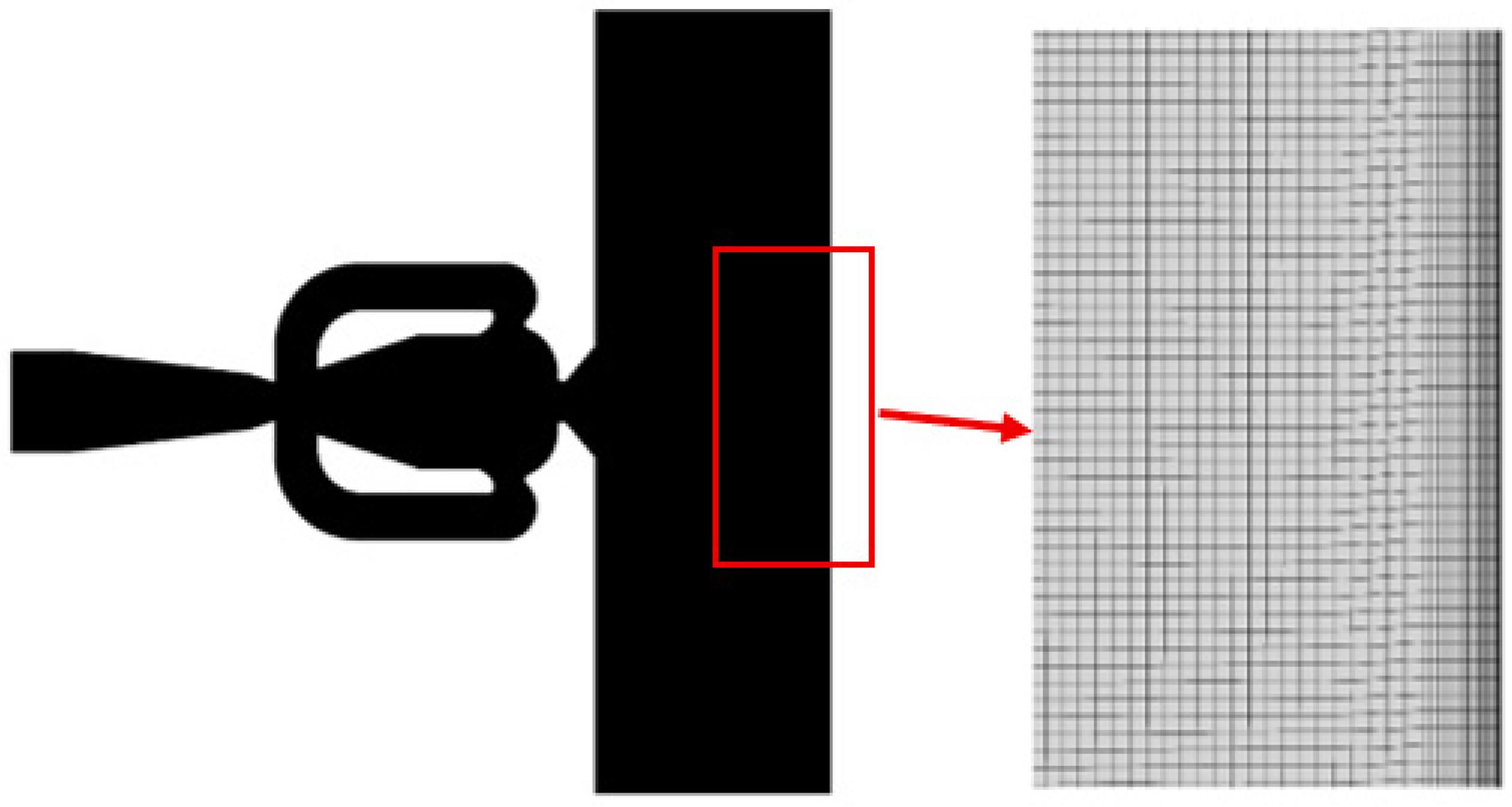
A comprehensive grid independence study was conducted to evaluate the influence of computational mesh resolution, as shown in Figure 2, on the numerical solution accuracy. Three distinct mesh configurations were systematically developed with increasing refinement levels, designated as N20 (coarse), N40 (medium), and N60 (fine), where the nomenclature reflects the element size relative to the nozzle throat diameter (D = 6.35 mm). The baseline element sizes were established as D/20, D/40, and D/60 for the respective meshes, ensuring progressive resolution enhancement. Special attention was given to boundary layer resolution, particularly near the oscillator walls, where flow gradients are most significant. The mesh construction incorporated 20 inflation layers normal to all wall surfaces, with the initial layer thickness carefully set at D/500 (12.7 μm) to properly resolve the viscous sublayer. A controlled growth factor of 1.15 was applied to subsequent layers, enabling a smooth transition from the near-wall region to the bulk flow domain. The sphere of influence method was implemented through spherical influence zones with 10D radii (63.5 mm) around the domain, ensuring adequate resolution of the jet interaction regions.
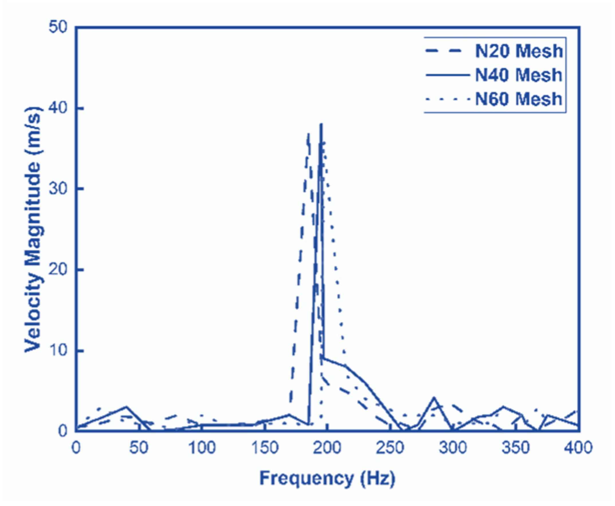
The grid independence assessment focused on the primary output parameter of oscillation frequency, analyzed through Fast Fourier Transform (FFT) of the numerical results as presented in Figure 3. The coarse N20 mesh predicted a dominant frequency of 180 Hz, while the medium N40 mesh yielded 195 Hz—an 8.3% increase reflecting improved flow feature resolution. The fine N60 mesh showed minimal further variation at 197 Hz, representing only a 1.02% difference from the N40 results. This convergence confirmed that the N40 mesh provided sufficient resolution for grid-independent solutions while maintaining computational efficiency. Hence, N40 mesh was used for further simulations.

3.2. Model Validation

Table 1 presents a comparative analysis of oscillation frequency predictions between the current 2D numerical study, previous numerical work, and experimental data. The results demonstrate excellent agreement, with the present model achieving relative errors of just 1.2% compared to prior numerical simulations and 2.6% against experimental measurements. These minor discrepancies confirm the predictive accuracy and reliability of our current 2D numerical approach for fluidic oscillator frequency analysis. The close alignment with both computational and experimental benchmarks validates the model’s capability to capture the essential flow physics governing oscillator behavior.
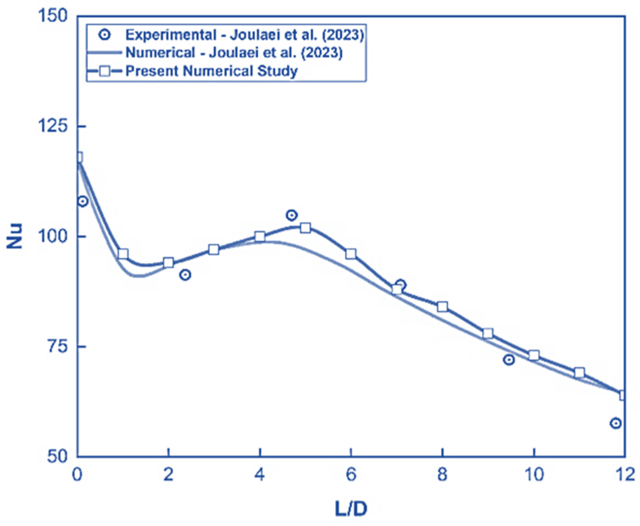
The heat transfer results from the present numerical study were carefully validated against the combined computational and experimental data reported by Joulaei et al. [26]. As shown in Figure 4, excellent agreement was observed between the time-average Nusselt number distributions from our simulations and the reference data. The maximum discrepancy with the computational results was approximately 7%, while comparison with experimental measurements showed even better agreement, with deviations of less than 2% at L/D = 5. These minor variations, particularly the close match with experimental values, demonstrate the accuracy and reliability of our numerical model in predicting the thermal performance of the fluidic oscillator.
Table 1. Validation of Computational Model.
Ref.Analysis MethodOscillation Frequency (Hz)% Change
Slupski et al. [27] Experimental346 Hz-
Alam and Kara [28]Numerical (2D)350 Hz1.2
Present StudyNumerical (2D)355 Hz2.6

4. Results and Discussion

The fluidic oscillator’s jet oscillation frequency plays a critical role in thermal performance when it is used in a sweeping jet impingement cooling system. Faster oscillations improve heat dissipation by boosting unsteady flow effects, leading to greater Nusselt number values. Meanwhile, pressure losses due to flow resistance must be considered, as they impact both dynamic behavior and jet impingement cooling system effectiveness.

4.1. Impact of Bleed-Feed Channel Width on Frequency

The oscillation frequency of a fluidic oscillator is significantly influenced by its geometric configuration. The present study examines oscillation frequency across different fluidic oscillator configurations, as shown in Figure 5. For the baseline smooth oscillator (no bleed-feed channel), frequencies follow conventional performance parameters. The baseline smooth oscillator exhibits lower frequencies (195 Hz) due to relying solely on natural fluidic feedback, where energy dissipation and weaker momentum transfer limit switching speed. In contrast, oscillators with bleed-feed channels demonstrate width-dependent frequency enhancement—as the channel width increases from 0.2D to 0.3D, the oscillation frequency rises from 435 Hz to 490 Hz. This improvement occurs because wider channels allow greater flow diversion into the feedback loop. When this amplified feedback flow re-enters the main chamber, it provides stronger momentum to push the jet across the Coanda surface, resulting in faster switching. The 0.3D/490 Hz case shows optimal performance, where maximum channel width enables the most efficient jet flipping action. It can also be observed that a 150% increase in oscillation frequency is achieved for channel width 0.3D as compared to the smooth oscillator. These results demonstrate how actively engineered feedback channels outperform passive smooth designs, with frequency directly proportional to bleed-feed channel width.
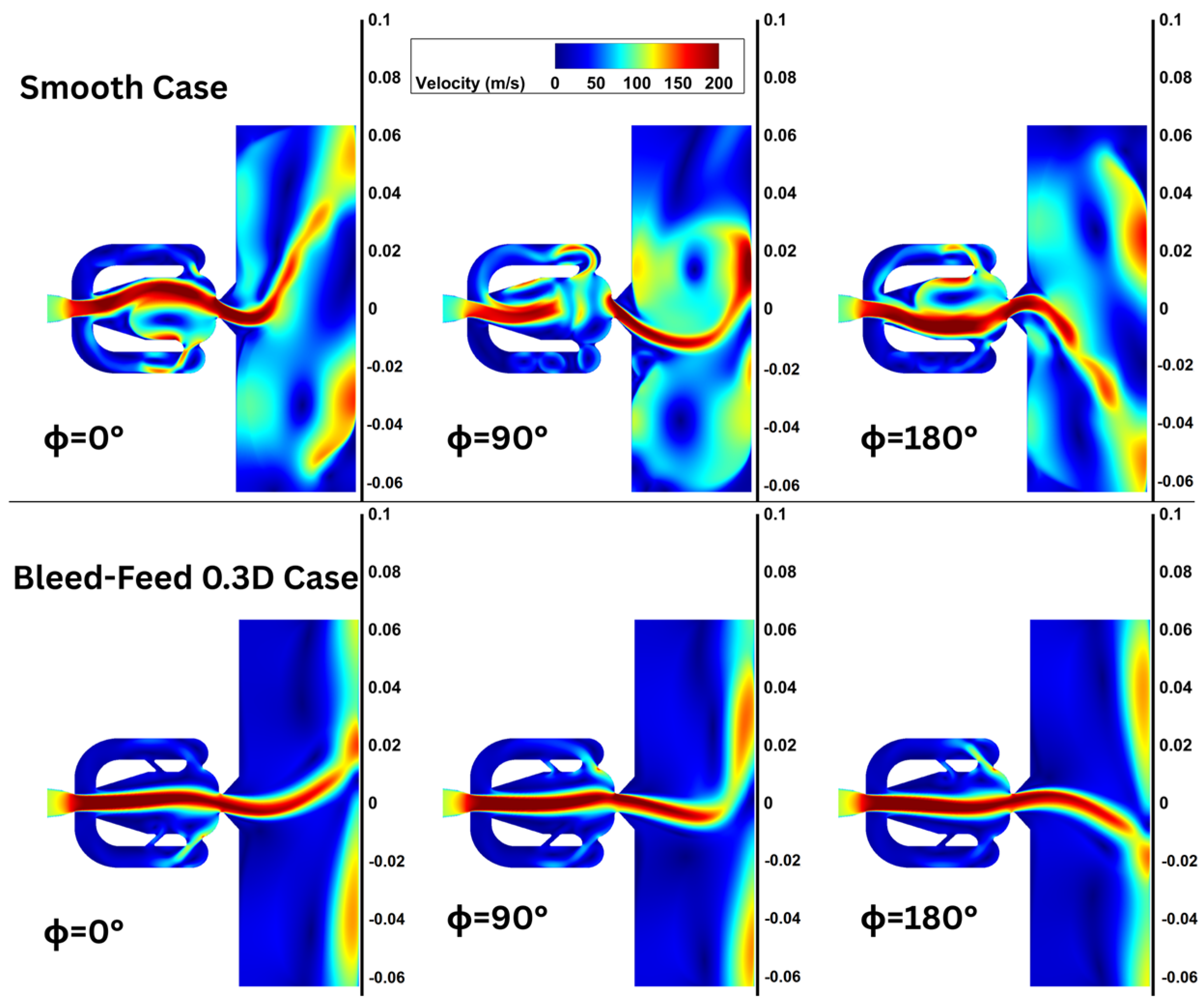
The velocity contours presented in Figure 6 show that in the smooth oscillator, the jet breaks down at 90° in the mixing chamber, leading to flow separation and vortex shedding that disrupts the oscillation cycle. This breakdown creates a delay as the jet must reattach to the Coanda surface before switching directions. In contrast, the bleed-feed design prevents complete main jet attachment to the Coanda surface by continuously extracting a portion of the flow through the bleed channel. This forces the jet to remain more centralized in the mixing chamber, avoiding the 90° breakdown seen in the smooth case. As a result, the jet transitions between sides more rapidly, with the geoe case attaining a higher frequency.

4.2. Impact of Bleed-Feed Channel Width on Pressure Drop

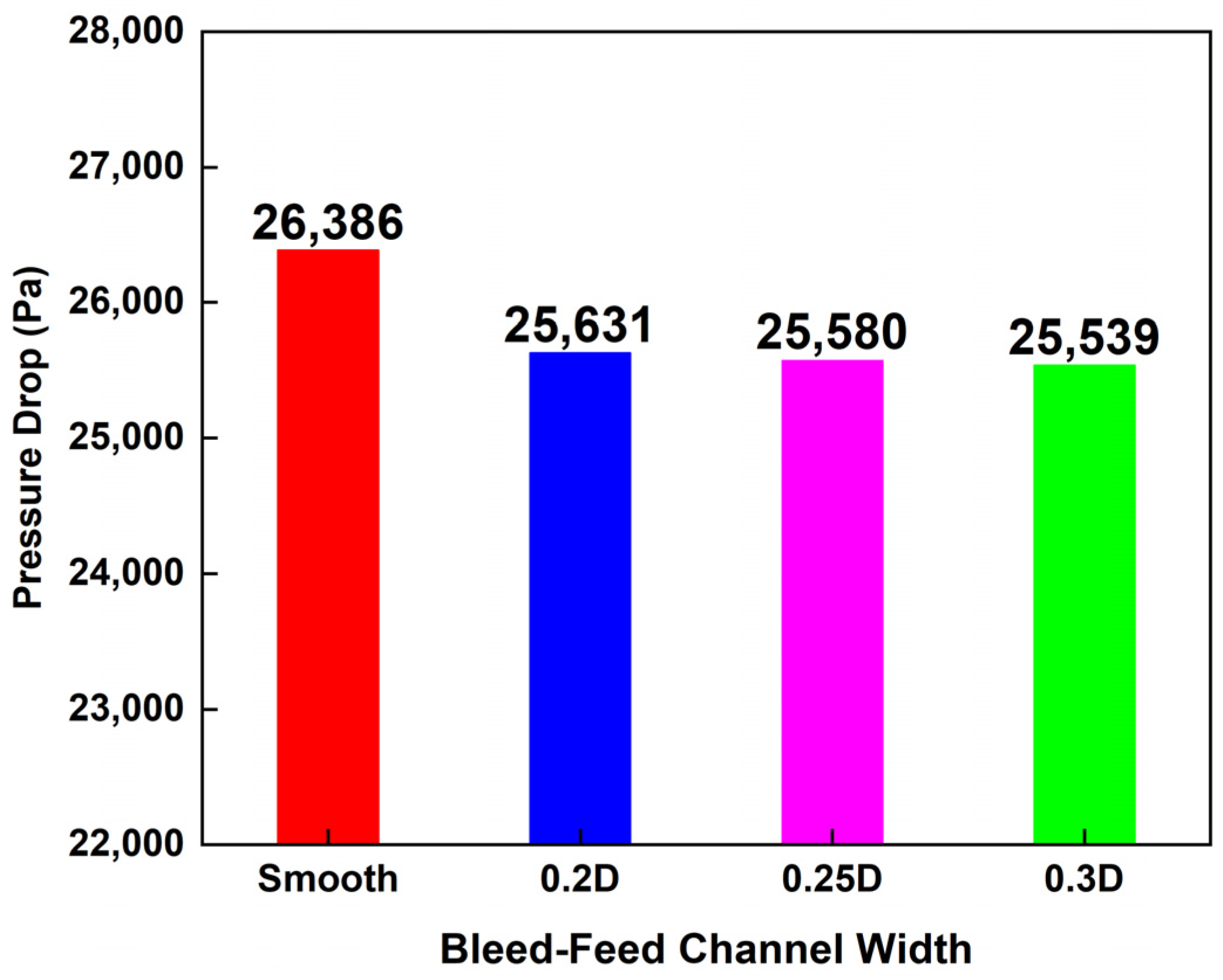
The pressure drop results, as shown in Figure 7, depict how geometric modifications in fluidic oscillators influence flow resistance. The smooth oscillator configuration shows the highest pressure drop, 26,386 Pa, as the unobstructed main jet creates significant energy dissipation. In contrast, oscillators with bleed-feed channels exhibit progressively lower pressure losses as the channel width increases. The narrowest 0.2D channel reduces the pressure drop to 25,631 Pa, while the intermediate 0.25D width achieves 25,580 Pa. The optimal 0.3D configuration yields the lowest pressure drop of 25,539 Pa, representing a 3.2% improvement over the smooth case. This systematic reduction occurs because the bleed-feed channels create alternative flow paths that divert fluid away from high-resistance regions in the main chamber. Wider channels (0.25D–0.3D) are particularly effective, allowing more flow to bypass turbulent zones and enabling smoother pressure recovery. Notably, the minimal difference between 0.25D and 0.3D cases suggests a performance threshold where additional width provides diminishing returns.
These results complement the previously observed frequency enhancements, demonstrating that bleed-feed channels simultaneously improve oscillation characteristics while reducing energy losses—a crucial advantage for efficient cooling system design. The inverse relationship between channel width and pressure drop underscores the importance of optimized geometric features in balancing performance and energy consumption in fluidic oscillators. In Figure 6, velocity contour plots, it is observed that in the smooth oscillator, the jet’s full attachment to the Coanda surface creates strong adverse pressure gradients, leading to flow separation and significant energy losses. The mixing chamber’s 90° breakdown further worsens this through turbulent dissipation. The velocity contours demonstrate this improvement, showing more uniform pressure recovery in the bleed-feed case compared to the chaotic low-pressure zones in the smooth oscillator at ϕ = 90°.

4.3. Impact of Bleed-Feed Channel Width on Nusselt Number

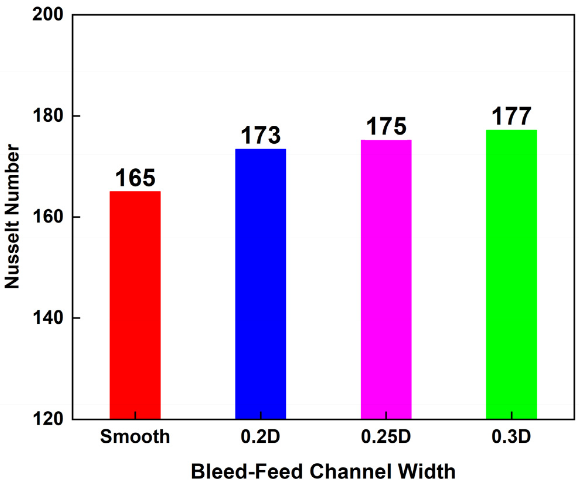
The Nusselt number results show significant thermal performance variations between the smooth oscillator and bleed-feed channel oscillators, as presented in Figure 8. The smooth oscillator shows the lowest Nusselt number 165, while oscillators with bleed-feed channels demonstrate progressive enhancement as the bleed-feed channel width increases, from 173 (0.2D) to 177 (0.3D), representing a 7.3% improvement as compared to the baseline smooth oscillator. This trend directly correlates with the previously observed oscillation frequency increases, as higher oscillation frequencies create more frequent jet impingement events and stronger flow unsteadiness. The 0.3D channel achieves optimal performance (Nu = 177) by combining two effects: (1) the wider channel produces higher oscillation frequencies, which reduce thermal boundary layer thickness through enhanced flow mixing, and (2) the additional feedback flow increases jet momentum during impingement. The results demonstrate that oscillators with bleed-feed channels simultaneously enhance both oscillation frequency and thermal performance. The wider bleed-feed channels result in faster jet switching that disrupts stagnant fluid layers more effectively while maintaining sufficient flow energy for heat removal.
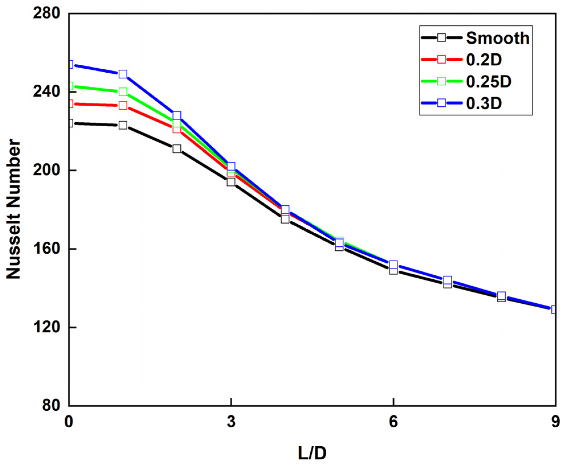
The Nusselt number distribution along the target surface length (L/D) reveals distinct heat transfer characteristics between different oscillator designs as presented in Figure 9. Near the stagnation point (L/D = 0), the smooth oscillator shows significantly lower Nusselt number values compared to bleed-feed channel designs, with the 0.3D configuration achieving the highest stagnation point Nusselt number. This heat transfer enhancement at the impingement zone occurs due to the following: (1) the bleed-feed channel’s higher oscillation frequency (490 Hz) creates more frequent jet impingement, and (2) the additional feedback flow increases jet momentum during direct wall collision. However, as the flow develops radially outward (increasing L/D), all designs gradually converge to similar Nusselt number values due to the weakening of impingement effects and boundary layer development. The 0.3D design maintains a slight advantage throughout the surface, demonstrating that wider channels preserve jet coherence longer. The rapid Nu decay in all cases follows typical impinging jet behavior, where maximum heat transfer occurs at the stagnation region and gradually decreases with target surface outward distance. These results highlight how bleed-feed channels particularly enhance heat transfer in the critical stagnation region where thermal loads are often highest, while maintaining comparable performance in radially away areas, making them superior for applications requiring focused cooling at specific hotspots.

5. Conclusions

This numerical investigation employed a two-dimensional unsteady Reynolds-averaged Navier–Stokes (URANS) approach with the k-ω SST turbulence model. The present study systematically evaluates the impact of bleed-feed channel geometry on the performance of fluidic oscillators, with particular emphasis on key jet parameters including oscillation frequency, pressure loss, and heat transfer characteristics. The results provide valuable guidance for enhancing fluidic oscillator designs in both flow dynamics and heat transfer applications.
The results demonstrate that introducing a bleed-feed channel significantly enhances oscillation frequency, reduces pressure drop, and improves heat transfer compared to a smooth oscillator design. The 0.3D channel width emerges as the optimal configuration, delivering a 150% increase in oscillation frequency and a 3.2% reduction in pressure drop. These improvements are attributed to the channel’s ability to strengthen feedback flow, thereby accelerating jet switching while minimizing energy losses. For heat transfer, the bleed-feed channel width 0.3D oscillator design achieves a 7.3% higher Nusselt number as compared to the smooth oscillator design. This enhancement results from the combined effects of higher oscillation frequency, which intensifies boundary layer disruption, and increased jet momentum due to reinforced feedback flow. Additionally, while the present study demonstrates a consistent frequency increase with channel width, further investigation is needed to determine whether an optimal bleed-feed channel width exists that maximizes oscillation frequency without compromising other performance metrics such as pressure recovery or thermal transfer efficiency.
These findings provide valuable insights for designing efficient fluidic oscillators in applications such as electronics cooling or gas turbine blade cooling, where high-frequency oscillations and targeted heat transfer are essential. Future work could explore 3D simulations or experimental validation to further refine the design guidelines.

Author Contributions

Conceptualization, L.H. and M.M.K.; methodology, L.H. and M.M.K.; software, L.H.; validation, L.H. and N.A.; formal analysis, K. and M.M.K.; investigation, L.H. and T.A.; resources, M.M.K. and N.A.; data curation, L.H., T.A. and M.M.K.; writing—L.H., K.; writing—review and editing, L.H., N.A. and M.M.K.; visualization, L.H., K., T.A. and M.M.K.; supervision, M.M.K. and N.A.; project administration, M.M.K. All authors have read and agreed to the published version of the manuscript.

Funding

This research received no external funding.

Institutional Review Board Statement

Not applicable.

Informed Consent Statement

Not applicable.

Data Availability Statement

Data are contained within the article.

Conflicts of Interest

The authors declare no conflicts of interest.

References

  1. Raghu, S. Feedback-Free Fluidic Oscillator and Method. U.S. Patent US 6,253,782 B1, 3 July 2001. [Google Scholar]
  2. Jafarian Amiri, A.; Farhadi, M. Numerical Investigation of a Single Feedback Loop Oscillator with Two Outlet Channels. Chem. Eng. Res. Des. 2019, 150, 206–217. [Google Scholar] [CrossRef]
  3. Hussain, L.; Khan, M.M. Recent Progress in Flow Control and Heat Transfer Enhancement of Impinging Sweeping Jets Using Double Feedback Fluidic Oscillators: A Review. J. Heat Transf. 2022, 144, 120802. [Google Scholar] [CrossRef]
  4. Stouffer, R. Oscillating Spray Device. U.S. Patent 4,151,955, 1 May 1979. [Google Scholar]
  5. Greenblatt, D.; Whalen, E.A.; Wygnanski, I.J. Introduction to the Flow Control Virtual Collection. AIAA J. 2019, 57, 3111–3114. [Google Scholar] [CrossRef]
  6. Schmidt, H.J.; Woszidlo, R.; Nayeri, C.N.; Paschereit, C.O. Separation Control with Fluidic Oscillators in Water. Exp. Fluids 2017, 58, 135. [Google Scholar] [CrossRef]
  7. Raman, G.; Raghu, S. Cavity Resonance Suppression Using Miniature Fluidic Oscillators. AIAA J. 2004, 42, 10–13. [Google Scholar] [CrossRef]
  8. Madadkon, H.; Fadaie, A.; Nili-Ahmadabadi, M. Experimental and Numerical Investigation of Unsteady Turbulent Flow in a Fluidic Oscillator Flow Meter with Extraction of Characteristics Diagrams. Modares J. Mech. Eng. 2013, 12, 30–42. [Google Scholar]
  9. Lacarelle, A.; Paschereit, C.O. Increasing the Passive Scalar Mixing Quality of Jets in Crossflow with Fluidics Actuators. J. Eng. Gas Turbine Power 2012, 134, 021503. [Google Scholar] [CrossRef]
  10. Kim, S.H.; Kim, H.D.; Kim, K.C. Measurement of Two-Dimensional Heat Transfer and Flow Characteristics of an Impinging Sweeping Jet. Int. J. Heat. Mass. Transf. 2019, 136, 415–426. [Google Scholar] [CrossRef]
  11. Fawzy, H.; Zheng, Q.; Ahmad, N.; Jiang, Y. Optimization of a Swirl with Impingement Compound Cooling Unit for a Gas Turbine Blade Leading Edge. Energies 2020, 13, 210. [Google Scholar] [CrossRef]
  12. Fawzy, H.; Zheng, Q.; Jiang, Y.; Lin, A.; Ahmad, N. Conjugate Heat Transfer of Impingement Cooling Using Conical Nozzles with Different Schemes in a Film-Cooled Blade Leading-Edge. Appl. Therm. Eng. 2020, 177, 115491. [Google Scholar] [CrossRef]
  13. Fawzy, H.; Zheng, Q.; Ahmad, N. Effect of Slot Area Ratio and Slot Angle on Swirl Cooling in a Gas Turbine Blade Leading Edge. J. Aerosp. Eng. 2020, 33, 04020046. [Google Scholar] [CrossRef]
  14. Bobusch, B.C.; Woszidlo, R.; Krüger, O.; Paschereit, C.O. Numerical Investigations on Geometric Parameters Affecting the Oscillation Properties of a Fluidic Oscillator. In Proceedings of the 21st AIAA Computational Fluid Dynamics Conference, San Diego, CA, USA, 24–27 June 2013; pp. 1–15. [Google Scholar]
  15. Baghaei, M.; Bergada, J.M. Fluidic Oscillators, the Effect of Some Design Modifications. Appl. Sci. 2020, 10, 2105. [Google Scholar] [CrossRef]
  16. Woszidlo, R.; Ostermann, F.; Nayeri, C.N.; Paschereit, C.O. The Time-Resolved Natural Flow Field of a Fluidic Oscillator. Exp. Fluids 2015, 56, 125. [Google Scholar] [CrossRef]
  17. Tajik, A.; Kara, K.; Parezanovic, V. Sensitivity of a Fluidic Oscillator to Modifications of Feedback Channel and Mixing Chamber Geometry. Exp. Fluids 2021, 62, 250. [Google Scholar] [CrossRef]
  18. Hossain, M.A.; Prenter, R.; Agricola, L.M.; Lundgreen, R.K.; Ameri, A.; Gregory, J.W.; Bons, J.P.; Researcher, P. Effects of Roughness on the Performance of Fluidic. In Proceedings of the 55th AIAA Aerospace Sciences Meeting, Grapevine, TX, USA, 9–13 January 2017. [Google Scholar]
  19. Jeong, H.S.; Kim, K.Y. Shape Optimization of a Feedback-Channel Fluidic Oscillator. Eng. Appl. Comput. Fluid Mech. 2018, 12, 169–181. [Google Scholar] [CrossRef]
  20. Hussain, L.; Khan, M.M.; Ahmad, N. Flow Performance Enhancement of a Fluidic Oscillator Through the Integration of Rectangular Ribs on Coanda Surface. J. Fluids Eng. 2024, 146, 111301. [Google Scholar] [CrossRef]
  21. Hussain, L.; Khan, M.M.; Ahmad, N. Flow Performance Improvement of Fluidic Oscillator Through Variation in Number of Ribs on Coanda Surface. J. Fluids Eng. 2025, 147, 111201. [Google Scholar] [CrossRef]
  22. Hussain, L.; Khan, M.M. The Influence of Location of Coanda Surface Ribs on Fluidic Oscillator Performance. In Proceedings of the 4th International Conference on Advances in Mechanical Engineering (ICAME-24), Islamabad, Pakistan, 8 August 2024; p. 3. [Google Scholar]
  23. Hussain, L.; Khan, M.M.; Ahmad, N. Design Optimization of Ribbed Fluidic Oscillator Using Integrated CFD-Taguchi-GRA Method. Eur. J. Mech.—B/Fluids 2025, 113, 204284. [Google Scholar] [CrossRef]
  24. Hussain, L.; Khan, M.M.; Ahmad, N.; Imran, M.; Shahzad, M.W. Taguchi-Based Optimization of a Fluidic Oscillator for Enhanced Thermal-Hydraulic Performance of an Impinging Sweeping Jet. Int. Commun. Heat Mass. Transf. 2025, 166, 109176. [Google Scholar] [CrossRef]
  25. Joulaei, A.; Nili-Ahmadabadi, M.; Yeong Ha, M. Numerical Study of the Effect of Geometric Scaling of a Fluidic Oscillator on the Heat Transfer and Frequency of Impinging Sweeping Jet. Appl. Therm. Eng. 2023, 221, 119848. [Google Scholar] [CrossRef]
  26. Joulaei, A.; Nili-Ahmadabadi, M.; Chun Kim, K. Parametric Study of a Fluidic Oscillator for Heat Transfer Enhancement of a Hot Plate Impinged by a Sweeping Jet. Appl. Therm. Eng. 2022, 205, 118051. [Google Scholar] [CrossRef]
  27. Slupski, B.J.; Tajik, A.R.; Parezanović, V.B.; Kara, K. On the Impact of Geometry Scaling and Mass Flow Rate on the Frequency of a Sweeping Jet Actuator. FME Trans. 2019, 47, 599–607. [Google Scholar] [CrossRef]
  28. Alam, M.; Kara, K. The Influence of Exit Nozzle Geometry on Sweeping Jet Actuator Performance. Fluids 2022, 7, 69. [Google Scholar] [CrossRef]
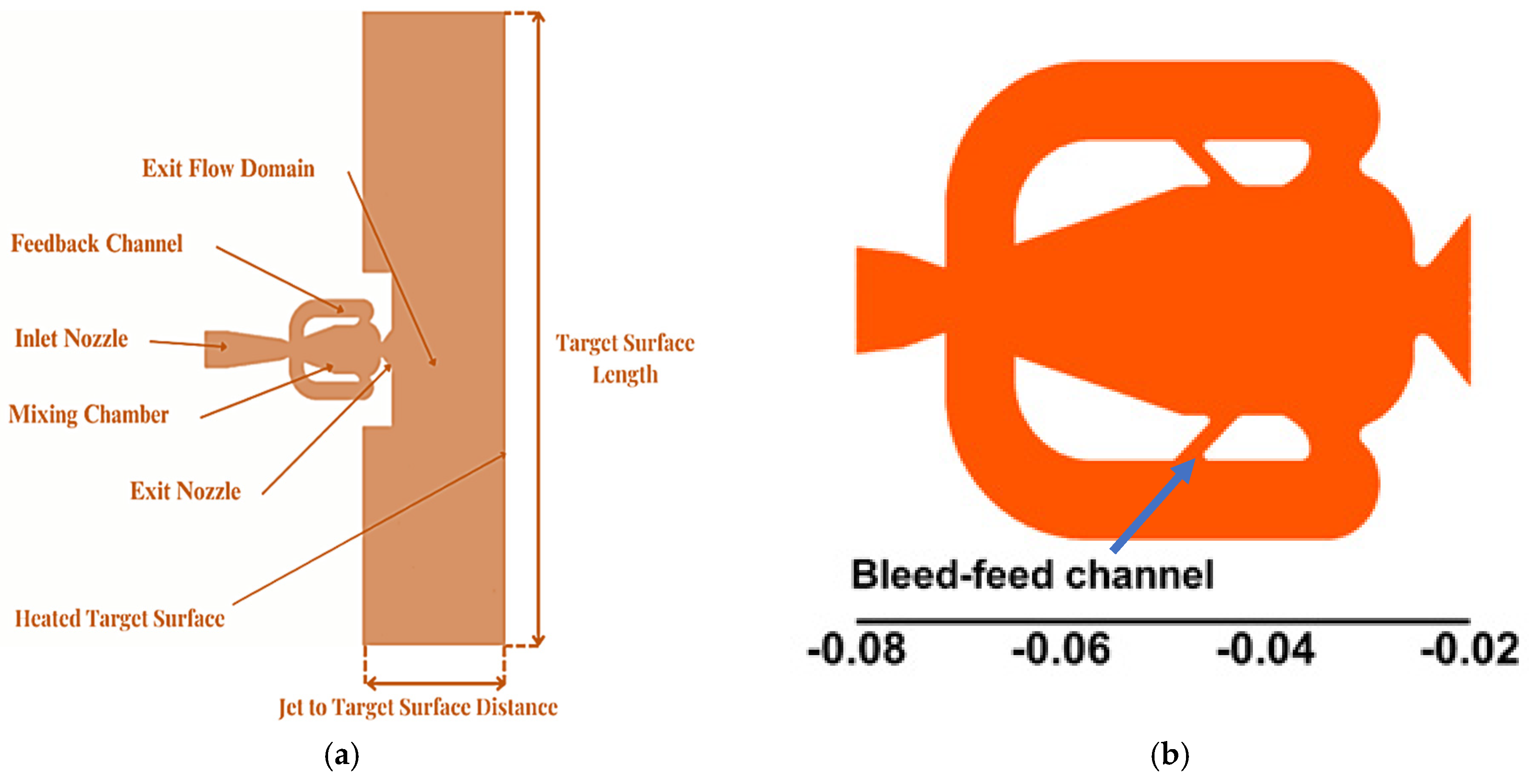
Figure 1. (a) Computational domain specifications for sweeping jet impingement. (b) Fluidic oscillator with bleed-feed channel used in the present study.
Engproc 111 00024 g001
Figure 2. Computational domain and impingement heated surface (zoomed) mesh used in the present study.
Engproc 111 00024 g002
Figure 3. FFT analysis of velocity magnitude sampled at (6 mm, 0 mm) for different meshes.
Engproc 111 00024 g003
Figure 4. Model Validation for the present study with [25,26] using Nusselt Number results.
Engproc 111 00024 g004
Figure 5. Oscillation frequency for different bleed-feed channel width oscillators.
Engproc 111 00024 g005
Figure 6. Velocity contours for smooth and bleed-feed channel oscillators at different phase angles.
Engproc 111 00024 g006
Figure 7. Pressure drop for different bleed-feed channel width oscillators.
Engproc 111 00024 g007
Figure 8. Nusselt number for different bleed-feed channel width oscillators.
Engproc 111 00024 g008
Figure 9. Nusselt number vs. target surface length variations for different bleed-feed channel width oscillators.
Engproc 111 00024 g009
Disclaimer/Publisher’s Note: The statements, opinions and data contained in all publications are solely those of the individual author(s) and contributor(s) and not of MDPI and/or the editor(s). MDPI and/or the editor(s) disclaim responsibility for any injury to people or property resulting from any ideas, methods, instructions or products referred to in the content.