Proceeding Paper

Adaptive Observer-Based Robust Control of Mismatched Buck DC–DC Converters for Renewable Energy Applications †

1
Department of Mechanical & Manufacturing Engineering, Pak-Austria Fachhochschule: Institute of Applied Sciences and Technology, Haripur 22621, Pakistan
2
Drive Team, Washing Machine-R&D Center, Beko Corporate, Istanbul 34000, Turkey
3
Department of Electrical & Computer Engineering, Riphah International University, Islamabad 44000, Pakistan
4
Department of Computer Sciences, University of Management and Technology, Lahore 54000, Pakistan
*
Author to whom correspondence should be addressed.
Presented at the 5th International Conference on Advances in Mechanical Engineering (ICAME-25), Islamabad, Pakistan, 26 August 2025.
Eng. Proc. 2025, 111(1), 22; https://doi.org/10.3390/engproc2025111022
Published: 27 October 2025

Abstract

This paper presents a new robust control strategy for buck DC–DC converters that achieve fast and robust voltage regulation in the presence of load disturbances and model uncertainties. First, an adaptive state observer is designed to estimate the inductor current and capacitor voltage by utilizing the output measurement. The observer gains are tuned online via a Lyapunov-based adaptation law, ensuring that the estimation error remains uniformly bounded, even when the disturbances act on the system. Based on the state estimates, an integral sliding-mode controller is designed in order to eliminate the steady state error and ensure the finite time sliding. The detailed stability proofs for both the observer and the sliding-mode controller are derived showing the finite-time reaching of the sliding surface and exponential convergence of the voltage error. Simulation results under varying load profiles confirm that the proposed scheme outperforms traditional sliding-mode designs in terms of disturbance rejection and settling time, while avoiding excessive chattering.

1. Introduction

Power converters have vast applications in the modern power-electronics systems, from portable electronics to renewable-energy systems. Amongst these power converters, the buck DC–DC converter is widely utilized for stepping down voltage with high efficiency and fast dynamic response [1,2,3]. However, the practical converters must operate under fluctuating loads and parameter uncertainties, which result in the degradation of the regulation performance, and they can even make the system unstable [4].
Traditional control strategies, like PID controllers, are widely utilized in the industry [5,6]. However, such controllers struggle with system uncertainties and disturbances. While the robust control schemes, e.g., sliding-mode control (SMC), have gained traction for their robustness against the disturbances and model inaccuracies, they also come with the trade-offs [7,8]. Conventional SMC applied to buck converters suffer from chattering and steady-state error due to the mismatched disturbances, where the disturbance does not directly affect the control input, and also due to the dependence on accurate measurements of all the system states, i.e., the inductor current and capacitor voltage [9,10]. Obtaining these state measurements usually requires additional, costly, or noisy sensors.
The observer-based SMC controllers are a popular choice because of their ability to estimate the unmeasured states using available outputs [11,12,13]. However, standard fixed-gain observers have limited robustness in case the converter’s parameters are not perfectly known [14]. Similarly, in the presence of large, unpredictable disturbances, their estimated values can become inaccurate and hence degrade the overall control performance [15]. Adaptive observers provide the solution by adjusting their gains online, but ensuring their stability and bounded estimation error under all the operating conditions requires careful design.
To overcome these limitations, this paper proposes a new adaptive observer-based integral sliding-mode control (AO-ISMC) scheme specifically designed for buck converters having mismatched disturbances and model uncertainties. Instead of having the fixed gains, an observer is proposed, whose gains continuously adapt online using a mathematically extensive Lyapunov-based adaptation law. This guarantees that the estimates of the inductor current and capacitor voltage should remain accurate and that the estimation error stays bounded, even when the significant disturbances are acting on the system or its parameters are not exactly known. By utilizing the state estimates, an integral action is included in order to eliminate the steady state error and ensure robustness.
In the following sections, the complete analytical modeling of the system is performed along with the controller design. The results section highlights the usefulness of the proposed controller in terms of disturbance rejection and perfect voltage regulation.

2. Description of Buck DC–DC Converter

Figure 1 shows the circuit diagram of the buck dc–dc converter. The continuous-conduction-mode buck converter is modeled by its inductor current i L , and the capacitor voltage is given by v C . Let u [ 0 ,   1 ] be the duty ratio, V i n the input voltage, R L the inductor resistance, L the inductance, C the capacitance, and R the load resistance, then the inductor dynamics are given as follows.
L d i L d t = u V i n R L i L v C
The capacitor dynamics are given as follows.
C d v C d t = i L v C R
The state vector is defined as x = [ i L   v C ] T , the input to the system is u , the system disturbance is d , and the measured output is y = v C . For compact analysis and control design, the state space model is then given as follows.
x ˙ = A x + B u + D d y = C x
where
  • A = R L L 1 L 1 C 1 R C , B =   V i n L 0 , D =   1 L 0 , C = 0 1 .
Equations (1)–(3) represent the mismatched nature of the buck dc–dc converter system.

3. Control Design

The proposed controller design consists of two phases. In the first step, an adaptive observer is designed in order to estimate the unmeasured state and disturbance, and in the next step, an integral sliding-mode controller is designed that uses these estimates in order to achieve robust voltage regulation.
From Equation (3), the plant model is written as below.
x ˙ = A x + B u + D d
A Luenberger-type observer with time-varying gain L ( t ) is constructed, having the observer’s state denoted by   x ^ and its output by y ^ . The observer equations are given as follows.
x ^ ˙ = A x ^ + B u + L ( t ) y C x ^   y ^ = C x ^
The estimation error is defined as e = x x ^ . Subtracting Equation (5) from the true model, i.e., Equation (4) yields as follows.
e ˙ = A L 0 C e l ~ ( t ) C e + D d
where the gain is split into a fixed nominal part L 0 and an adaptive correction l ~ t , so that L t = L 0 + l ~ t and l ~ t = l ~ 1 ( t ) l ~ 2 ( t ) .
For driving both the state error e and the gain error l ~ to manageable levels, we adopt the Lyapunov function as:
V ( e , l ~ ) = 1 2 e T P e + 1 2 γ l ~ T l ~
where P = P T > 0   is the positive-definite matrix solving the below equation.
A L 0 C T P + P A L 0 C = Q ,           Q > 0
and γ > 0   is an adaptation rate. Equation (8) guarantees that, if l ~ 0 and d 0 , the nominal error dynamics e ˙ = ( A L 0 C ) e would decay exponentially:
d d t 1 2 e T P e = 1 2 e T Q e < 0 .
Differentiating V along the trajectories of both e and l ~ gives the following result.
V ˙ = d d t 1 2 e T P e + d d t 1 2 γ l ~ T l ~
V ˙ = e T P e ˙ + 1 γ l ~ T l ~ ˙
Substituting the value of e ˙ from Equation (6) gives the following result.
e T P e ˙ = e T P A L 0 C e l ~ C e + D d
e T P A L 0 C e = 1 2 e T Q e
e T P l ~ C e = l ~ T ( C P e )
Therefore, putting these values in V ˙ equation gives the following result.
V ˙ = 1 2 e T Q e l ~ T ( C P e ) + e T P D d + 1 γ l ~ T l ~ ˙
The adaptive control law is designed as follows.
l ~ ˙ = γ C P e
Substituting Equation (10) into Equation (9) leads to the following bound.
V ˙ 1 2 e T Q e + e P D d
Since Q > 0 ,
e T Q e λ m i n Q e 2
Therefore,
V ˙ 1 2 λ m i n Q e 2 + e P D d
which shows that e t   remains uniformly ultimately bounded. In practice, increasing the design gains Q or γ reduces the estimation error bound.
By utilizing the observer’s voltage estimate v ^ C , the output tracking error e v is defined as follows.
e v = V ^ C V ref
where v ref is the desired DC output. The integral sliding surface is introduced as follows.
σ t = e v t + λ 0 t e v τ d τ ,                   λ > 0 .
Differentiating Equation (13) and substituting the observer dynamics from Equation (5) (with constant reference) yields the following result.
σ ˙ = C x ^ ˙ + λ e v
σ ˙ = C A x ^ + C B u + C L y C x ^ + λ e v
The reaching law is designed as follows.
σ ˙ = η s i g n σ ,                   η > 0 .
Equation (14) is solved for the control input as the sum of an equivalent term and a switching term as follows.
u = u e q u s w
Therefore,
u eq = C B 1 C A x ^ + C L y C x ^ + λ e v
The switching term is given as follows.
u sw = C B 1 η s i g n σ
The stability on the sliding surface is established by choosing the following Lyapunov function.
V s ( σ ) = 1 2 σ 2
By utilizing the reaching law given in Equation (15), the following result is obtained.
V s ˙ = σ σ = ˙ η σ < 0      f o r   σ 0 ,
The above result guarantees finite-time convergence to σ = 0 . Once on the manifold, it satisfies the following relation.
e ˙ v + λ e v = 0 ,
Therefore, the voltage error decays exponentially to zero, which completes the control design.

4. Results

To validate the proposed adaptive integral sliding-mode control, time-domain simulations are conducted in MATLAB/Simulink 2022 under realistic operating scenarios. The simulations were conducted using Simulink, with a fixed-step solver (auto, automatic solver selection) and a sampling time of 0.0001 s. The simulation duration was set to 20 s. These settings were chosen to ensure accurate and reliable results. The nominal values of the parameters for the mismatched buck converter are provided in Table 1. Initially, the value of the reference voltage is set at 20 V, and the load resistance value is set to 20 Ω . The Lyapunov weight vector Q is set to 1 × 10 6 I 2 . The adaptation rate γ is chosen as 1 × 10 4 , while the integral weight λ is selected as 100. The reaching rate η is set to 5, and the discrete update interval for adaptation law t is set to 50 μ s .
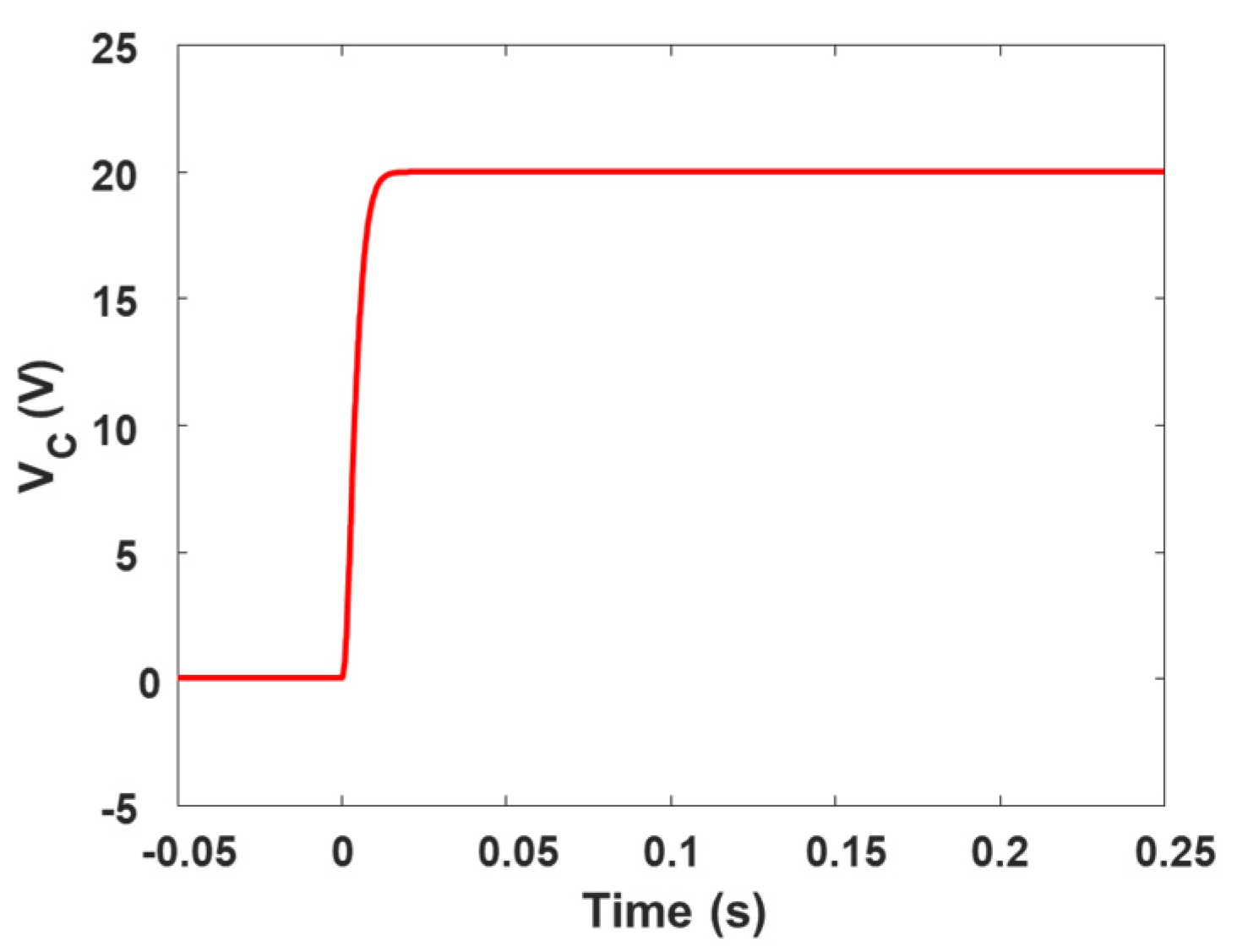
Figure 2 shows the reference tracking performance of the proposed adaptive controller. The output voltage tracks the reference voltage accurately in the presence of mismatched disturbance. The response time is 23 ms, and there is no overshoot present in the output response.
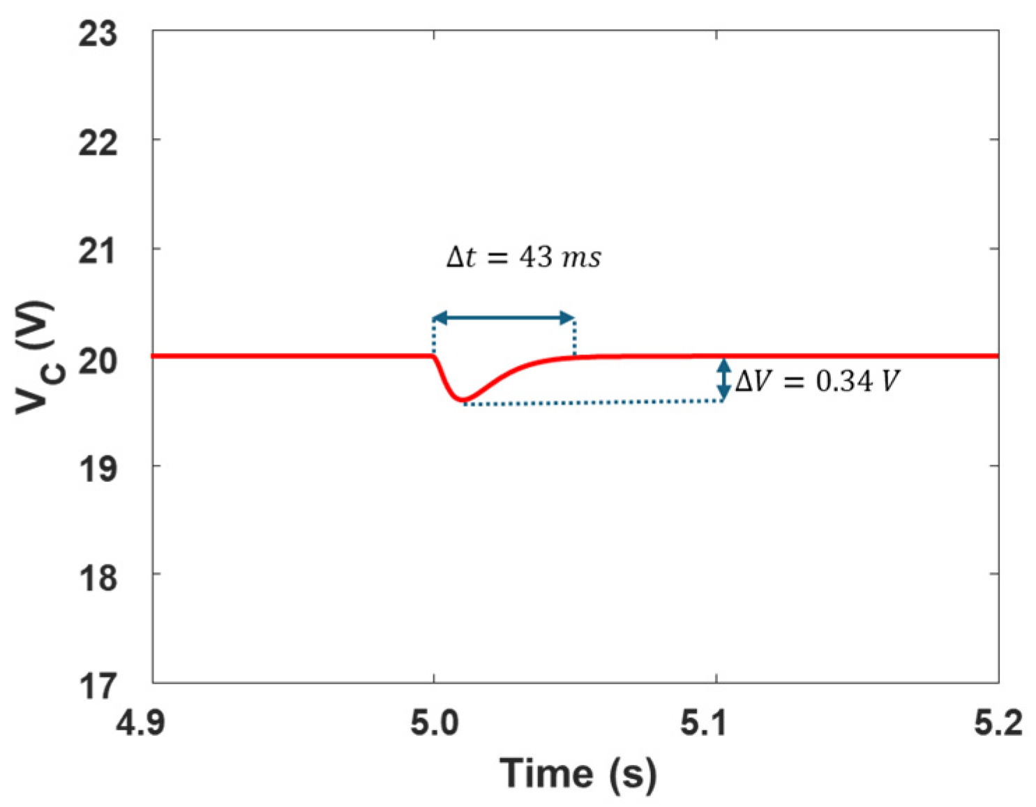
For verifying the performance of the designed controller during the load variation scenario, the reference voltage is kept fixed at 20 V, while the load resistance is varied from 10 Ω to 20 Ω . The resulting voltage regulation process of the proposed controller is shown in Figure 3. The settling time of the resulting response is 43 ms, with a voltage variation of 0.34 V due to the load variation.
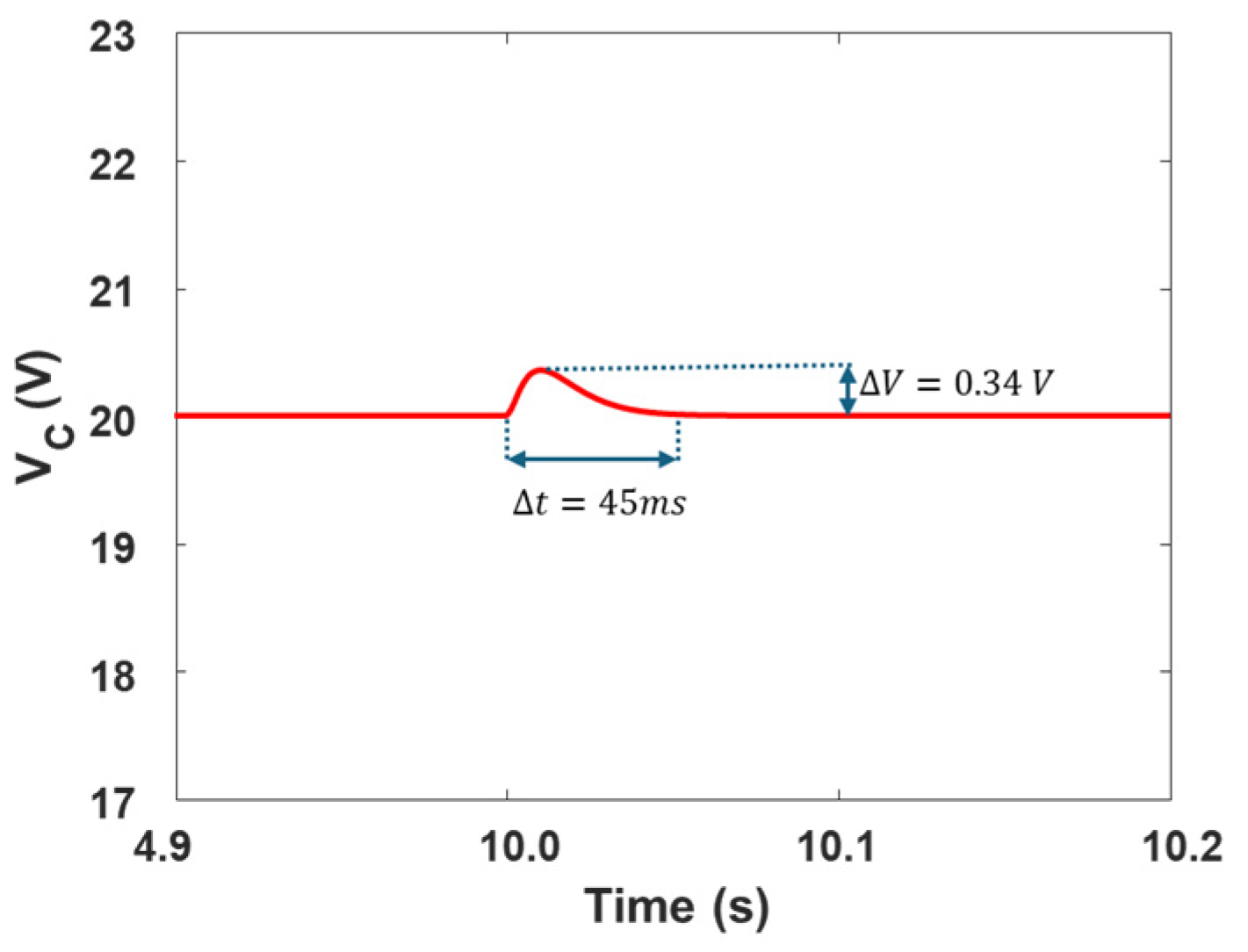
Similarly, the load is increased from 20 Ω to 10 Ω , and the resulting response of the converter is given in Figure 4. The settling time is 45 ms, and the observed voltage overshoot is 0.34 V.
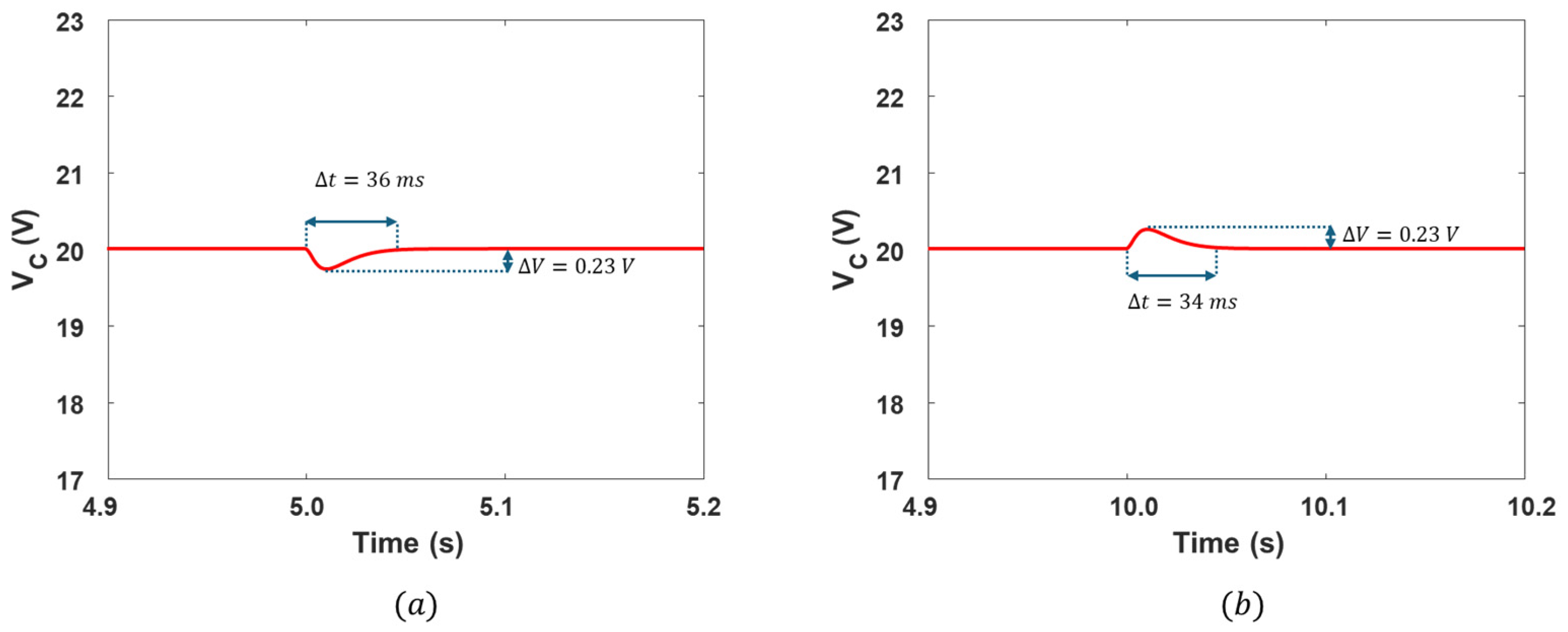
In order to verify the robustness properties of the designed controller in the presence of model uncertainties, the inductor and capacitor values are perturbed as L ¯ = L + 20 % and C ¯ = C + 20 % , respectively. The resulting output response is given in Figure 5. Despite the presence of uncertainty, the converter is still able to achieve good performance, indicating the robustness of the design controller.
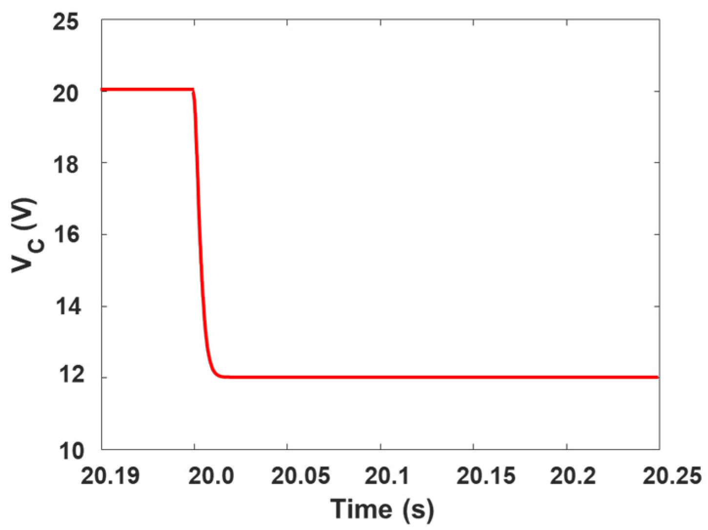
The reference voltage is changed from 20 V to 12 V while keeping the load resistance constant. The resulting output voltage waveform is given in Figure 6, showing good robustness against the reference voltage variation.
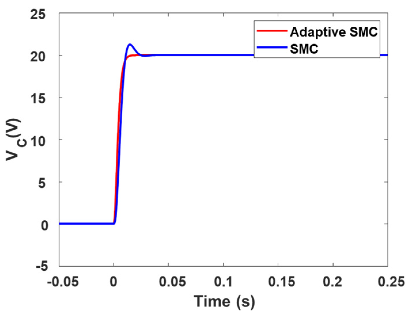
Finally, the performance of the designed adaptive controller is compared against the conventional SMC controller. The resulting output response of the two controllers is provided in Figure 7. The comparison indicates the effectiveness of the proposed control system in terms of settling time and overshoot in the presence of mismatched uncertainties.

5. Conclusions

An integrated adaptive observer and integral sliding-mode control framework was designed for the buck DC–DC converters having mismatched load disturbances and model uncertainties. By designing a real-time Lyapunov-based adaptation law for the observer gains, a fast and accurate estimation of both inductor current and disturbance dynamics was achieved by utilizing only the output voltage measurement. Incorporating an integral term directly into the sliding surface eliminated the steady-state voltage error without sacrificing the finite-time convergence. Simulation results under the reference voltage variation, sudden load changes, and model uncertainties validated the effectiveness of the proposed adaptive controller. For future work, the proposed control framework can be extended to real-time embedded implementation and experimental validation on a hardware prototype, which would then provide further insights into its practical feasibility and performance under the realistic conditions.

Author Contributions

Conceptualization, methodology, investigation, data curation, H.S.Z.; writing—original draft preparation, H.S.Z. and A.U.; editing, H.S.Z. and A.Z.; review, S.K. All authors have read and agreed to the published version of the manuscript.

Funding

This research received no external funding.

Institutional Review Board Statement

Not applicable.

Informed Consent Statement

Not applicable.

Data Availability Statement

No new data were created or analyzed in this study. Data sharing is not applicable to this article.

Conflicts of Interest

Abasin Ulasyar were employed by the Beko Corporate. The remaining authors declare that the research was conducted in the absence of any commercial or financial relationships that could be construed as a potential conflict of interest.

References

  1. Ibarra, E.; Arias, A.; de Alegría, I.M.; Otero, A.; De Mallac, L. Digital control of multiphase series capacitor buck converter prototype for the powering of HL-LHC inner triplet magnets. IEEE Trans. Ind. Electron. 2021, 69, 10014–10024. [Google Scholar] [CrossRef]
  2. Babes, B.; Mekhilef, S.; Boutaghane, A.; Rahmani, L. Fuzzy approximation-based fractional-order nonsingular terminal sliding mode controller for DC–DC buck converters. IEEE Trans. Power Electron. 2021, 37, 2749–2760. [Google Scholar] [CrossRef]
  3. Zad, H.S.; Ulasyar, A.; Zohaib, A.; Irfan, M.; Yaqoob, Z.; Haider, S.A. Robust & Optimal Predictive Current Control for Bi-Directional DC-DC Converter in Distributed Energy Storage Systems. Eng. Proc. 2024, 75, 26. [Google Scholar]
  4. Malge, S.V.; Patil, S.L.; Deshpande, A.S.; Aher, P.K. Mismatched Disturbance Estimation Based Sliding Mode Control of DC-DC Power Converter. In Proceedings of the 2nd International Conference on Intelligent Technologies (CONIT), Karnataka, India, 24–26 June 2022. [Google Scholar]
  5. Zad, H.S.; Ulasyar, A.; Zohaib, A. Adaptive Observer Based Output Voltage-Tracking Control of DC-DC Boost Converters. In Proceedings of the 21st International Bhurban Conference on Applied Sciences and Technology (IBCAST), Islamabad, Pakistan, 20–23 August 2024; pp. 584–588. [Google Scholar]
  6. Alshalalfah, A.L.; Hamad, G.B.; Mohamed, O.A. Towards safe and robust closed-loop artificial pancreas using improved PID-based control strategies. IEEE Trans. Circuits Syst. I Regul. Pap. 2021, 68, 3147–3157. [Google Scholar] [CrossRef]
  7. Sheh Zad, H.; Ulasyar, A.; Zohaib, A.; Khattak, A. Adaptive sliding mode predictive power control of three-phase AC/DC converters. Proc. Inst. Mech. Eng. Part I J. Syst. Control Eng. 2022, 236, 897–912. [Google Scholar] [CrossRef]
  8. Liu, Z.; Lin, X.; Gao, Y.; Xu, R.; Wang, J.; Wang, Y.; Liu, J. Fixed-time sliding mode control for DC/DC buck converters with mismatched uncertainties. IEEE Trans. Circuits Syst. I Regul. Pap. 2022, 70, 472–480. [Google Scholar] [CrossRef]
  9. Qin, C.; Zhang, Z.; Fang, Q. Adaptive backstepping fast terminal sliding mode control with estimated inverse hysteresis compensation for piezoelectric positioning stages. IEEE Trans. Circuits Syst. II Express Briefs 2023, 71, 1186–1190. [Google Scholar] [CrossRef]
  10. Fan, D.; Zhang, X.; Pan, W. Sliding mode control for strict-feedback nonlinear impulsive systems with matched disturbances. IEEE Trans. Circuits Syst. II Express Briefs 2023, 71, 787–791. [Google Scholar] [CrossRef]
  11. Zad, H.S.; Ulasyar, A.; Zohaib, A.; Irfan, M.; Haider, S.A.; Yaqoob, Z. Adaptive Sliding Mode Control of DC–DC Buck Converter with Load Fluctuations for Renewable Energy Systems. Eng. Proc. 2024, 75, 10. [Google Scholar]
  12. Zhang, P.; Kao, Y.; Hu, J.; Niu, B.; Xia, H.; Wang, C. Finite-time observer-based sliding-mode control for Markovian jump systems with switching chain: Average dwell-time method. IEEE Trans. Cybern. 2021, 53, 248–261. [Google Scholar] [CrossRef] [PubMed]
  13. Dong, S.; Liu, M.; Wu, Z.G.; Shi, K. Observer-based sliding mode control for Markov jump systems with actuator failures and asynchronous modes. IEEE Trans. Circuits Syst. II Express Briefs 2020, 68, 1967–1971. [Google Scholar] [CrossRef]
  14. Zhang, H.; Yan, Y.; Mu, Y.; Ming, Z. Neural network-based adaptive sliding-mode control for fractional order fuzzy system with unmatched disturbances and time-varying delays. IEEE Trans. Syst. Man Cybern. Syst. 2023, 53, 5174–5184. [Google Scholar] [CrossRef]
  15. Zhen, S.; Yaen, X.; Chengchen, D.; Kun, Z.; Yushan, H.; Yong, H. Disturbance observer based finite-time coordinated attitude tracking control for spacecraft on SO3. J. Syst. Eng. Electron. 2020, 31, 1274–1285. [Google Scholar] [CrossRef]
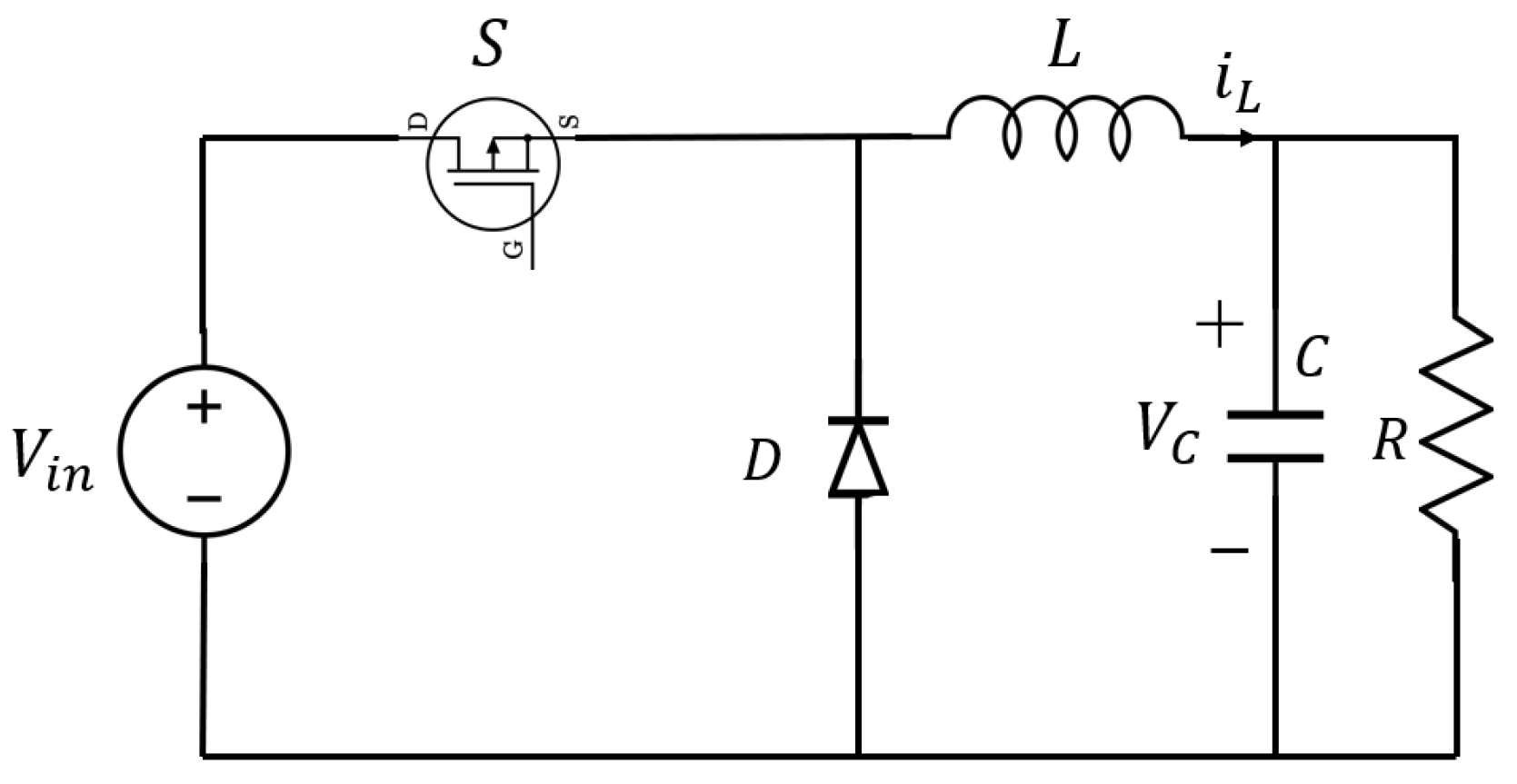
Figure 1. Buck DC–DC converter system.
Engproc 111 00022 g001
Figure 2. Output voltage response of buck DC-DC converter with reference voltage of 20 V.
Engproc 111 00022 g002
Figure 3. Output voltage response of the converter with load variation from 10 Ω to 20 Ω .
Engproc 111 00022 g003
Figure 4. Output voltage response of the converter with load variation from 20 Ω to 10 Ω .
Engproc 111 00022 g004
Figure 5. Output voltage response of the converter in the presence of model uncertainties. (a) Inductor parameter uncertainty. (b) Capacitor parameter uncertainty.
Engproc 111 00022 g005
Figure 6. Output voltage response of the converter with reference voltage changed from 20 V to 10 V .
Engproc 111 00022 g006
Figure 7. Performance comparison of the designed adaptive SMC controller and conventional SMC controller.
Engproc 111 00022 g007
Table 1. Buck DC–DC converter’s nominal parameters.
DescriptionParameterValue
Reference Voltage V r e f 20→15 V
Input Voltage V i n 30 V
Filter Inductor L 1.5 mH
Load Resistance R 10→20   Ω
Filter Capacitor C 2200 μ F
Disclaimer/Publisher’s Note: The statements, opinions and data contained in all publications are solely those of the individual author(s) and contributor(s) and not of MDPI and/or the editor(s). MDPI and/or the editor(s) disclaim responsibility for any injury to people or property resulting from any ideas, methods, instructions or products referred to in the content.