1. Introduction
Electric vehicles (EVs) are becoming more and more popular worldwide as a result of the pressing need for cleaner, low emission mobility. Ensuring the thermal stability of lithium-ion batteries, particularly under fast charging/discharging rates and fluctuating ambient conditions, is one of the major problems in EV technology. Inadequate heat control can result in decreased battery life, performance deterioration, and, in extreme situations, thermal runaway. Lithium iron phosphate (LFP) batteries, one of several battery chemistries, provide improved thermal stability and safety, which qualifies them for EV applications. However, because of their reduced energy density and susceptibility to temperature changes, effective battery thermal management systems (BTMSs) are required to ensure optimal performance within the recommended 15–35 °C range.
Recent research has led to the development of diverse BTMS designs. According to Maiorino et al., liquid-cooling solutions can greatly improve thermal uniformity by lowering peak battery temperatures by up to 20% [
1]. A hybrid system that combines air cooling and heat pipes was proposed by Behi et al. and worked well under dynamic operation conditions [
2]. The capability of phase-change material (PCM) and mini-channel systems in controlling localized heating was emphasized by Lin et al. [
3]. By combining PCM, fins, and mini-channels, Hekmat et al. created a small cooling system that allowed prismatic battery modules to have temperature variations of less than 5 °C [
4]. In support of these methods, Patel and Rathod talked about hybrid passive–active cooling techniques that struck a balance between efficiency and affordability [
5]. Liu et al. stressed the necessity of CFD-assisted heat management systems that were empirically verified and customized for actual EV battery layouts [
6]. Benabdelaziz et al. also suggested a new external liquid-cooled battery pack with an aluminum cold plate, which was used as a basis for designing practical BTMS configurations [
7].
Meshram et al. designed a CFD-validated cold plate for EV batteries [
8], while Buidin and Mariasiu reviewed air, liquid, PCM, and heat pipe cooling, highlighting hybrids as most effective [
9]. Similarly, Zhang et al. developed a hybrid PCM–liquid-cooling system with stable thermal performance [
10], and Sevilgen et al. optimized multi-channel cold plates to cut LTO cell temperatures by 45% [
11], while Du and Lu proposed physics-informed neural networks as faster, more accurate thermal models [
12]. With an emphasis on performance improvement and design optimization, Hamed et al. examined recent developments in external cooling solutions for lithium-ion battery thermal management [
13]. Dai and Long advanced refrigerant direct cooling for fast charging [
14], and Wiriyasart et al. demonstrated nanofluid modules lowering battery temperature by ~29% despite a higher pressure drop [
15].
Despite these advances, few studies simultaneously combine computational and experimental evaluation of a copper-channeled aluminum cooling plate specifically designed for LFP battery modules. Addressing this gap, the present study develops a BTMS incorporating 3D CAD modeling, CFD simulations using ANSYS 2023 R2 Fluent, and experimental validation through a lab-scale prototype for liquid cooling. The performance of the system is evaluated under practical heat loads, offering a scalable, cost-effective, and thermally reliable solution for modern EV applications.
2. Problem Formulation
This study addresses the thermal management of a lithium iron phosphate (LFP) battery pack using a liquid-cooling plate designed to maintain cell temperatures within the optimal operating range of 15 °C to 35 °C. The battery pack was composed of 192 soft pouch cells connected in a series parallel configuration with the individual cell size of 325 mm × 135 mm × 11.2 mm and a total pack size of 373 mm × 204 mm × 140 mm. The cooling plate, modeled in SolidWorks, is made of aluminum and measures 1630 mm × 1200 mm × 40 mm. It contains embedded copper channels of 30 mm inner diameter, to circulate ethylene glycol coolant beneath the battery module.
The system is modeled as a heat transfer problem involving both solid and fluid domains, under steady-state conditions. Internal heat generation is applied at the battery base to simulate real operating conditions, and the coolant enters at 290 K. The objective is to assess temperature distribution, surface uniformity, and coolant temperature rise, using both CFD simulations and experimental measurements to evaluate the effectiveness of the proposed cooling configuration.
3. Methodology
A detailed thermal analysis was performed to investigate the cooling efficiency of a battery pack consisting of 192 units of soft pouch cells assembled in combined series–parallel connection manner. Three-dimensional CAD models of both the battery pack and the cold plate were developed using SolidWorks 2021. These geometries were subsequently imported to ANSYS Fluent 2023 R2 for CFD simulations, in which the thermal performance of the battery system was studied. This involved mapping temperature contours of the fluid domain and the battery itself, simulating flow in the cooling plate and copper tubes using a basic SST model. Lightweight and suitable equipment, including pipes, thermocouples, a cooling plate, an aluminum heat sink, a pump, and a heater, were carefully chosen and put together for experimental validation. Controlled experiments were performed on the prototype to assess the cooling system’s thermal performance and validate the simulation results.
3.1. CAD Modeling
A three-dimensional CAD model of the battery module was developed using SolidWorks 2021to replicate a realistic pouch cell battery pack used in mid-sized electric vehicles and is presented in the figures below.
Each cell has the dimensions 325 mm × 135 mm × 11.2 mm, based on dimension benchmarks from commercially available LFP pouch cells such as those used in BYD and CATL systems. These cells are stacked and packaged into a module with an overall dimension of 373 mm (L) × 204 mm (W) × 140 mm (H), accommodating the cell stack, spacer gaps for thermal expansion, and structural casing. These dimensions also consider practical constraints for thermal simulation and fabrication of the experimental prototype.
Figure 1 illustrates a cell module, battery pack, battery cell and full battery assembly below.
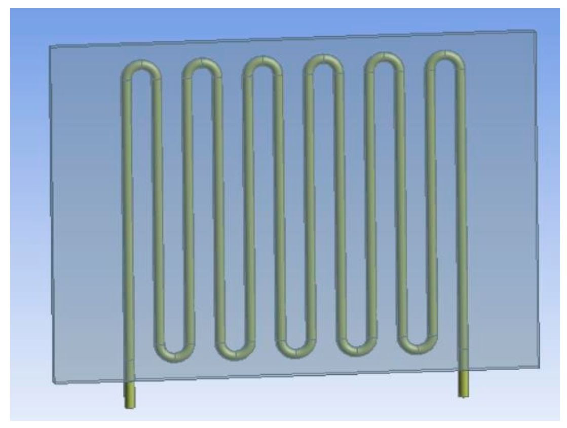
The cooling plate was also modeled in SolidWorks 2021. It is made of aluminum for its favorable strength-to-weight ratio and thermal conductivity, with internal serpentine copper channels embedded to enhance convective heat removal. The plate has dimensions of 1630 mm in length, 1200 mm in width, and 40 mm in thickness. Cooling channels of copper have an inner diameter of 30 mm. The CAD model as shown in
Figure 2 was created to optimize the contact area between the battery module and the cooling surface, enabling precise simulation of heat transfer processes and efficient coolant flow.
3.2. CFD Analysis
The CFD simulations were performed using a pressure-based steady-state solver in ANSYS 2023 R2 Fluent suitable for problems of incompressible fluid flow and heat transfer. The k-ω turbulence model for shear stress transport (SST) was chosen due to its accuracy and resilience in addressing near-wall flow behavior and accurately capturing thermal boundary layers within the serpentine copper channels. For pressure–velocity coupling, the SIMPLE algorithm was employed to ensure stability as well as convergence in the flow field. Second-order upwind schemes were applied for momentum, energy, and turbulence equations to improve solution accuracy. All solid–fluid interfaces were assigned no-slip boundary conditions, and wall heat transfer was modeled through conduction in solids and convection in fluids. Convergence was considered accomplished when residuals dropped less than 10
−4 for continuity, momentum, and energy equations. This setup ensures the reliable resolution of temperature gradients and flow characteristics critical to evaluating the cooling system’s performance. Investigation parameters used in the simulations are listed in
Table 1 below.
3.2.1. Meshing
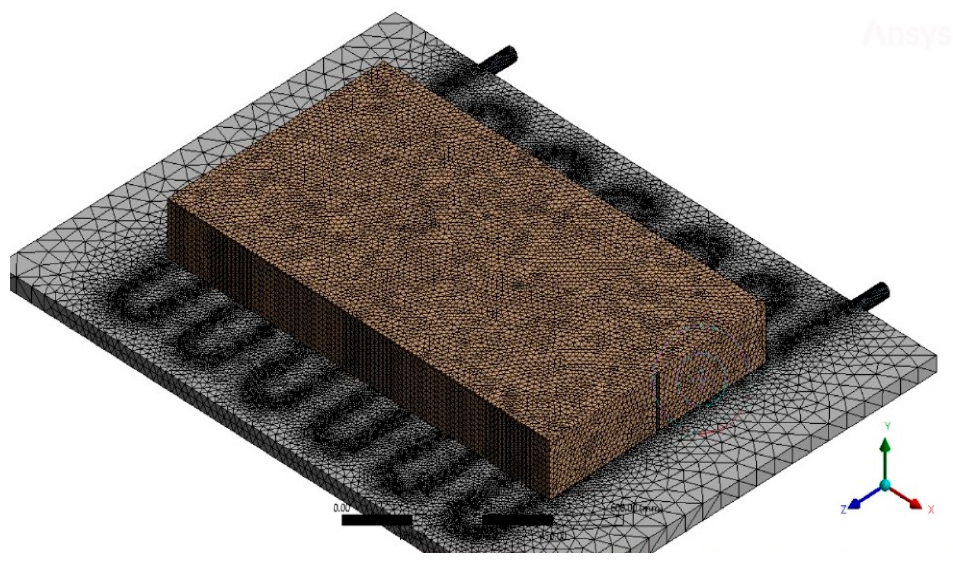
Meshing of the computational domain was performed using ANSYS 2023 R2 Meshing, employing a hybrid structured mesh with tetrahedral elements for the fluid regions and hexahedral elements where possible in the solid regions to ensure accurate resolution of thermal gradients. A finer mesh was applied in critical areas, such as around the copper channels and at the battery-cooling plate interface, to capture steep temperature and velocity gradients. The mesh size of the battery pack is 20mm whereas the mesh element size of the cooling plate is 95 mm. The mesh comprised approximately 2,105,078 elements and 668,432 nodes. Body sizing controls were used on the cooling plate and battery surfaces, and inflation layers were applied near the walls to improve the near-wall resolution required for SST turbulence modeling. The mesh quality was verified to maintain skewness below 0.85 and an aspect ratio below 5 to ensure solution stability.
Figure 3 shows the meshed geometry below.
A mesh independence study as shown in
Figure 4, was conducted using multiple mesh densities. As shown in
Figure 4, the predicted temperature gradient continued to rise up to a mesh size of 110 million elements, reaching approximately 305 K. Beyond this point, further mesh refinement had negligible impact, indicating mesh convergence. The final mesh with ~2.1 million elements was selected for its balance between accuracy and computational efficiency.
3.2.2. Simulations
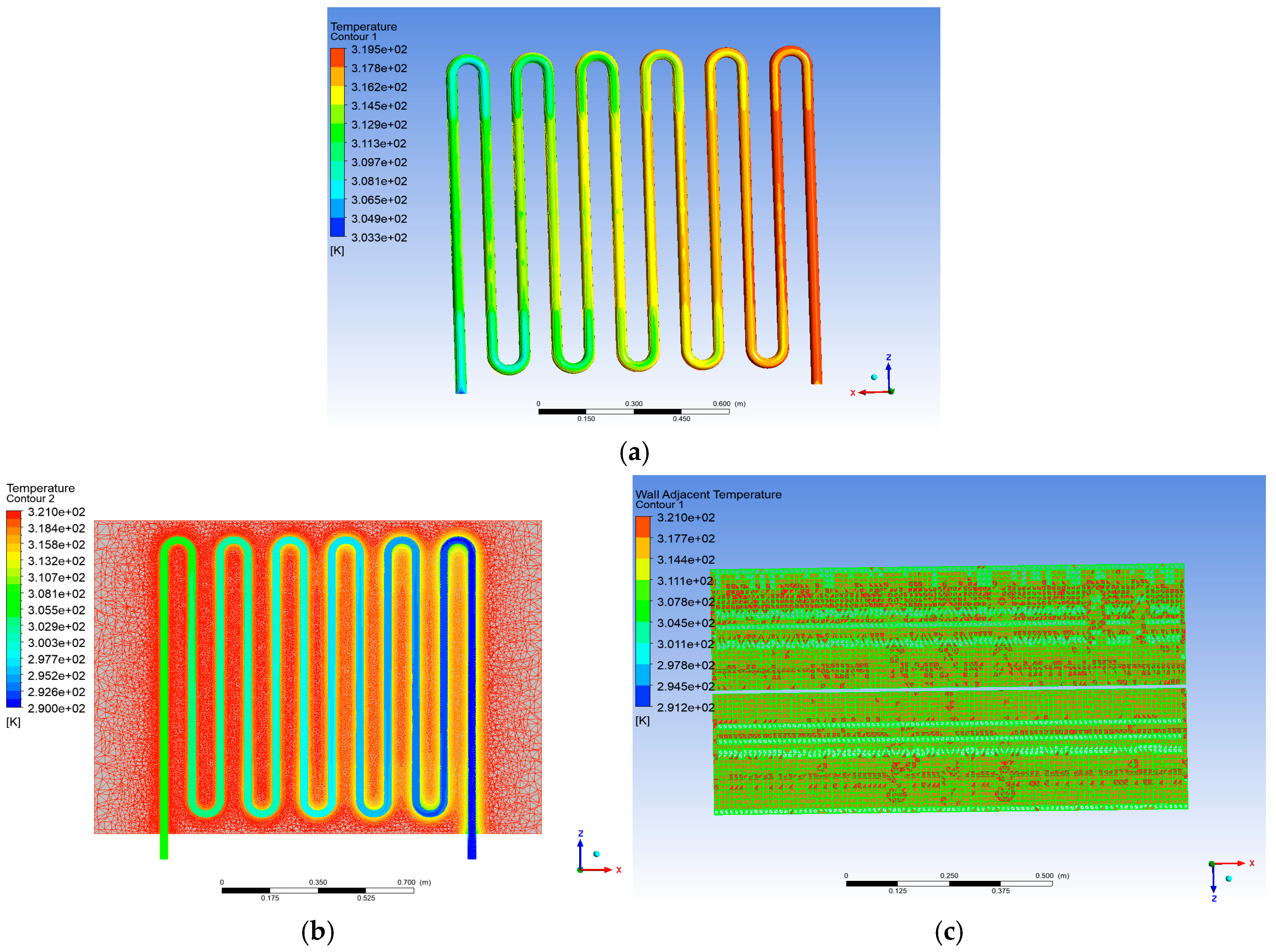
The simulation was run in a steady-state environment with the coolant (ethylene glycol) entering the copper channels at 290 K and 1.5 kg/s of mass flow rate. A heat flux was applied at the base of the battery pack to simulate internal heat generation. All solid–fluid interactions were subjected to no-slip boundary conditions. The outlet was set to atmospheric pressure, and all walls were assumed adiabatic except the battery–plate interface to accurately capture heat transfer. Results of simulations are shown in
Figure 5 below.
3.3. Experimentation
The purpose of EV battery heat management experiments is to verify computational models, optimize design, guarantee dependability, bolster safety, boost efficiency, and collect empirical data. To assemble an experimental apparatus for EV battery heat management we used the following:
A cooling plate serving as a conduit for heat.
An aluminum plate to disperse heat and replicate the surface of a battery.
Coolant, pumped throughout the system.
A heater to mimic the production of battery heat and heat the aluminum plate.
Thermocouples, located on the aluminum plate and at the cooling plate’s surface and coolant’s inlet and outlet to monitor temperature.
A pump, connected to the cooling plate and back in a coolant loop.
3.3.1. Cooling Plate
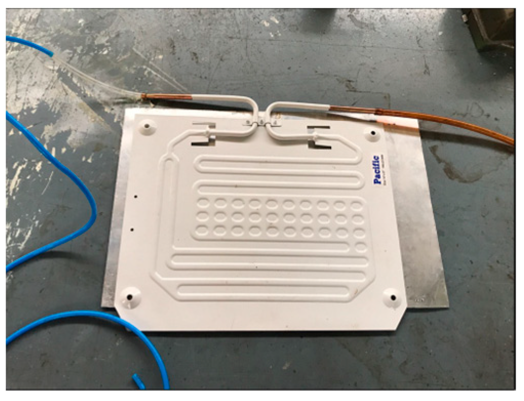
Cooling plates as shown in
Figure 6, remove heat generated during operation, keeping temperatures appropriate for better battery performance and longevity. They offer structural support, evenly distribute heat, and connect with cooling systems to optimize thermal management.
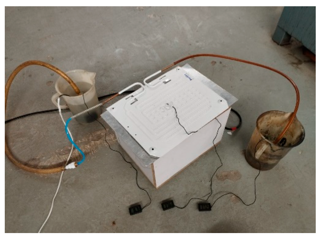
3.3.2. Experimental Setup for CFD Validation
A lab-scale experimental setup was developed to validate the CFD results. The aluminum plate, which evenly distributes the heat, is warmed by the heater to replicate battery heat in the experimental setup for EV battery thermal management. Coolant is pumped throughout the system, returning it from the aluminum plate to the cooling plate, where it dissipates heat. Thermocouples, positioned at the coolant inlet, outlet, the aluminum plate surface, and the cooling plate, track temperature throughout the operation, giving information that is used to evaluate the cooling system’s efficacy and the overall performance of thermal management. The inlet fluid temperature was maintained at 16.2 °C, and steady-state conditions were ensured before recording the data. The physical configuration matched the geometry used in the CFD model to ensure consistency between simulation and experiment. The final setup is shown in
Figure 7.
3.3.3. Experimental Results
Experimental validation was conducted using a prototype setup with thermocouples placed at coolant inlet and outlet, cooling plate surface, and aluminum plate (battery base) as shown in
Figure 8 below. The inlet temperature was measured at 16.2 °C, closely matching the simulation value of 16.9 °C. The cooling plate and aluminum plate temperatures were recorded at 34.8 °C and 47.2 °C, respectively, showing excellent agreement with simulated results of 34.9 °C and 46.9 °C. The coolant outlet temperature, however, was lower in the experiment (26.1 °C) compared with the simulation (37.9 °C), likely due to unaccounted ambient heat losses or simplified boundary assumptions. Overall, the close match at critical points confirms the accuracy of the CFD model and supports the effectiveness of the proposed cooling design.
4. Results and Discussion
The simulations have been run and the results indicate that the fluid comes into the channel (inlet) with a temperature reading of 290 K and as it flows in the copper channel, it absorbs the heat from the battery pack, which raises its temperature to a value of 310 K and hence, at the exit (outlet), it has a higher temperature of 310 K, thereby finally indicating a temperature increase of approximately 20 K in the coolant due to heat absorption from the battery pack. This temperature difference reflects effective convective heat transfer within the cooling plate. The SST turbulence model captured the temperature distribution across the battery surface, with the maximum cell surface temperature remaining below 315 K—well within the safe operational range for LFP batteries.
Moreover, temperature contours revealed uniform heat removal across the battery base, with slight hotspots forming near channel bends where coolant velocity decreased. The simulation also showed the copper channel temperatures rising from ~303 K at the inlet region to ~319.5 K at the outlet, closely aligning with the coolant temperature profile. Mesh independence was confirmed by running three mesh configurations (1.2 M, 2.1 M, and 2.7 M elements), showing less than 1.5% deviation in peak battery temperature, thus validating mesh sufficiency.
Numerical results were validated against experimental measurements. During the experimental phase, a simple setup was built with a surface-mounted heater to simulate battery heat flux. A pump circulated coolant through the cooling plate’s copper channels to simulate convective cooling. The aluminum plate served as the battery surface and was heated accordingly. Temperature data was recorded using thermocouples mounted at the coolant intake and exit, as well as on the surfaces of the cooling and aluminum plates. The measured temperature gradient closely matched the simulation findings, validating the numerical model. The temperature of liquid increased from 290 K to 300 K, and the temperature of the aluminum plate reduced by using the cooling plate to optimize the operating temperature, that is, 308 K, thus closely validating our simulation results with our experimental results.
Figure 9 presents a comparative bar chart illustrating the agreement between the numerical simulation and experimental temperature results.
5. Conclusions
The combined approach of CFD analysis and experimentation effectively designed an EV battery thermal management system. The CFD simulations predicted a 20 Kelvin difference in temperature between THE coolant’s inlet and outlet, indicating heat absorption from the battery pack. The copper channels facilitated efficient heat transfer, as evidenced by the rising temperature profile around them in the simulations. Furthermore, the experimentation successfully validated these predictions.
Author Contributions
Conceptualization, R.T., H.A., Z.W., and M.I.; methodology, H.A.; software, R.T. and H.A.; validation, M.I. and Z.W.; formal analysis, R.T. and H.A.; investigation, R.T. and H.A.; resources, R.T. and M.I.; data curation, R.T. and H.A.; writing—original draft preparation, R.T.; writing—review and editing, M.A. and T.I.K.; visualization, M.A.; supervision, M.A.; project administration, M.A. All authors have read and agreed to the published version of the manuscript.
Funding
This research received no external funding.
Institutional Review Board Statement
Not Applicable.
Informed Consent Statement
Not Applicable.
Data Availability Statement
The raw data supporting the conclusions of this article will be made available by the authors on request.
Acknowledgments
The authors sincerely acknowledge the invaluable support of the lab staff and engineers, as well as the financial support provided by the Institute of Space Technology.
Conflicts of Interest
The authors declare no conflicts of interest.
Abbreviations
The following abbreviations are used in this manuscript:
| CFD | Computational fluid dynamics |
| EV | Electric Vehicle |
| LFP | Lithium Iron Phosphate |
| BTMS | Battery Thermal Management Systems |
References
- Maiorino, A.; Cilenti, C.; Petruzziello, F.; Aprea, C. A review on thermal management of battery packs for electric vehicles. Appl. Therm. Eng. 2024, 238, 122035. [Google Scholar] [CrossRef]
- Behi, H.; Karimi, D.; Behi, M.; Ghanbarpour, M. A new concept of thermal management system in Li-ion battery using air cooling and heat pipe for electric vehicles. Appl. Therm. Eng. 2020, 174, 115280. [Google Scholar] [CrossRef]
- Lin, J.; Liu, X.; Li, S.; Zhang, C.; Yang, S. A review on recent progress, challenges and perspective of battery thermal management system. Int. J. Heat Mass Transf. 2021, 167, 120834. [Google Scholar] [CrossRef]
- Hekmat, S.; Tavana, P.; Molaeimanesh, G. A novel compact battery thermal management system comprising phase change material, mini-channels, and fins suitable for EV battery packs. J. Energy Storage 2024, 82, 110392. [Google Scholar] [CrossRef]
- Patel, J.; Rathod, M. Recent developments in the passive and hybrid thermal management techniques of lithium-ion batteries. J. Power Sources 2020, 480, 228820. [Google Scholar] [CrossRef]
- Liu, W.; Placke, T.; Chau, K. Overview of batteries and battery management for electric vehicles. Energy Rep. 2022, 8, 4058–4084. [Google Scholar] [CrossRef]
- Benabdelaziz, K.; Lebrouhi, B.; Maftah, A.; Maaroufi, M. Novel external cooling solution for electric vehicle battery pack. Energy Rep. 2020, 6, 262–272. [Google Scholar] [CrossRef]
- Meshram, M.J.S. Design of cold plate for a battery pack, its experimental analysis and simulation. J. Phys. Conf. Ser. 2023, 2601, 012019. [Google Scholar] [CrossRef]
- Buidin, T.I.C.; Mariasiu, F. Battery thermal management systems: Current status and design approach of cooling technologies. Energies 2021, 14, 4879. [Google Scholar] [CrossRef]
- Zhang, Y.; Feng, Q.; Liu, Y.; Li, B.; Zhao, K.; Wang, W. Investigations of lithium-ion battery thermal management system with hybrid PCM/liquid cooling plate. Processes 2023, 11, 345. [Google Scholar] [CrossRef]
- Demir, H.; Sevilgen, M.G. Experimental and numerical investigations on the thermal performance of three different cold plates designed for the electrical vehicle battery module. Sustainability 2023, 15, 14162. [Google Scholar] [CrossRef]
- Duan, Z.; Lu, R. Physics-informed neural networks for advanced thermal management in electronics and battery systems: A review of recent developments and future prospects. Batteries 2025, 11, 25. [Google Scholar] [CrossRef]
- Hamed, M.M.; El-Tayeb, A.; Moukhtar, I.; El Dein, A.Z.; Abdelhameed, E.H. A review on recent key technologies of lithium-ion battery thermal management: External cooling systems. Results Eng. 2022, 16, 100703. [Google Scholar] [CrossRef]
- Dai, N.; Long, J. Research on fast charging battery thermal management system based on refrigerant direct cooling. Sci. Rep. 2023, 13, 845. [Google Scholar] [CrossRef] [PubMed]
- Wiriyasart, S.; Hommalee, C.; Sirikasemsuk, S.; Prurapark, R.; Naphon, P. Thermal management system with nanofluids for electric vehicle battery cooling modules. Case Stud. Therm. Eng. 2020, 18, 100583. [Google Scholar] [CrossRef]
| Disclaimer/Publisher’s Note: The statements, opinions and data contained in all publications are solely those of the individual author(s) and contributor(s) and not of MDPI and/or the editor(s). MDPI and/or the editor(s) disclaim responsibility for any injury to people or property resulting from any ideas, methods, instructions or products referred to in the content. |
© 2025 by the authors. Licensee MDPI, Basel, Switzerland. This article is an open access article distributed under the terms and conditions of the Creative Commons Attribution (CC BY) license (https://creativecommons.org/licenses/by/4.0/).

