Abstract
The radiofrequency identification (RFID) interface is used in a controller area network (CAN) bus system to enhance the performance of stacked fuel cells. In addition, a personal computer base logic analyzer (LA) is utilized to monitor and analyze data transmitted over the CAN bus. The LA enables the visualization of digital signals, identification of data patterns, and troubleshooting of communication protocols. The combination of the CAN bus with the RFID interface and LA provides an effective solution for testing and monitoring digital communication systems. The result of this study proves that LA is applied in series-connected fuel cells. The advantages of the RFID CAN bus are validated by modern communication protocols.
1. Introduction
The controller area network (CAN) bus is a serial communication protocol designed to enable reliable data exchange between electronic devices, particularly in automotive and industrial environments [1,2]. The frame of the CAN protocol offers a 1 Mb/s baud rate for transmission speed, efficient bandwidth usage, and error check and fault detection (CRC) [3,4,5,6]. The analysis of the CAN bus signals is crucial to understanding the characteristics of this protocol-based communication. The CAN bus signals are transmitted between two Arduino UNO boards using a logic analyzer (LA) with Zeroplus Studio software [7,8]. The monitoring-controlling system for stacked fuel cells employs one Arduino “Write” to send data sourced from radiofrequency identification (RFID) sensors to trigger an ultrasonic sensor and a DHT11 humidity and temperature sensor for environment examination, while another Arduino “Read” receives the data and displays the results on an inter-integrated circuit (I2C) interfaced liquid crystal display (LCD) screen, as well as controllable actuators such as servo fan cooling and alert buzzer response [9,10,11].
Figure 1a illustrates the 3D model of the Arduino UNO integrated with an MCP2515 chip to build a node module of the CAN bus as a commander sending instructions from an RFID reader to drive sensors. The 3D node of the CAN bus for driving servo and buzzer devices is shown in Figure 1b. The indicators display discrete fuel cells as a power generator based on an Arduino CAN system to follow remote monitoring orders.

Figure 1.
(a) Three-dimensional node of Arduino UNO with an MCP2515 chip as a commander and (b) CAN bus 3D node as a slaver for driving a fan motor, a warning buzzer, and LED indicators.
With the help of a decoding oscilloscope and Zeroplus Studio V1.00.04 software, CAN bus signals were analyzed to verify data integrity, timing accuracy, and the configured bit rate at 500 kbps. The analysis also involved CAN signals to examine the transmitted data and identify communication patterns. For monitoring digital signals, transmission errors or anomalies were detected in the sent data. The test results in this study demonstrated that the analyzed CAN bus signals exhibited high consistency in data transmission, adhering to the specified protocol. This result enables the enhancement of the performance of the CAN bus communication and its benefits in microcontroller-based systems.
2. CAN System Integrated with RFID
2.1. CAN RFID Control Design for Stacked 20 Fuel Cells
We developed a controlling and monitoring function for the fuel cell of the FC140-20 (rated power 200 W) model based on the CAN bus with an RFID interface for flexible and remote access operation. In the CAN bus-based system, each node sends and receives data independently. The protocol employs a priority-based arbitration mechanism that ensures high-priority messages are transmitted first without disrupting other communications. Its reliability is further reinforced by built-in error detection methods such as cyclic redundancy checking (CRC) and acknowledgment (ACK), making the CAN bus well-suited for critical applications in the fuel cell stack system, as shown in Figure 2.
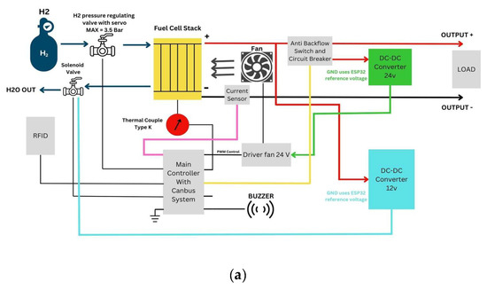
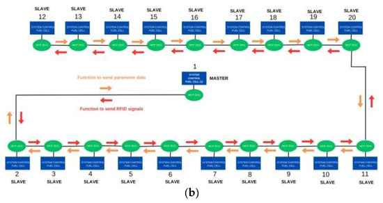
Figure 2.
(a) RFID integrated an individual fuel cell on CAN bus system with a cooling fan motor and warning buzzer and (b) monitored logic design for controlling 20 fuel cells in LED indicators or LCD information display.
In this study, we investigated how to apply multiple monitoring technologies to fuel cell energy instead of using a traditional control system for advanced networking techniques. For a multi-sensing and communication in the process, a variety of fuel cell electrical generations were reviewed (Figure 2) [12]. The CAN system is responsible for managing and monitoring the fuel cells from the second unit (#2) to the twentieth unit (#20) equipped with an RFID sensor. There are two main conditions, namely locked and unlocked, representing active and inactive statuses, respectively. The whole system regulates the fuel cells by controlling relays in each node (controlled unit) based on the status. Communication between systems is established using serial communication through the CAN bus (MCP2515), where RFID signals from the master (#1) controller are transmitted to each fuel cell (from #2 to #20) node to ensure optimal coordination of the network.
Each controlled unit (node) from the 2nd to 20th fuel cell acts as an actuator, meaning that it receives RFID data from the master unit (1st) on the CAN system and controls the relays under the received command and information. Additionally, each controlled node on the CAN system sends its operational parameters back to the master controller for real-time monitoring and managing, as shown in Figure 2b.
2.2. Software Integrity of Stacked Fuel Cells
The flowchart (Figure 3) describes diagnostic programming. To troubleshoot hardware problems, diagnostic routines are embedded in the Arduino UNO master and slave programming software in C++ language. The following coding snippet ensures that the MCP2515 module is working properly. This diagnostic function verifies that the MCP2515 module is detected, making troubleshooting easier during operation. The LA is used to check the CAN bus communication status while setting the bit rate to 500 kbps to ensure stable communication. The desired sent data of the message frames includes distance information, temperature, and RFID authentication status.
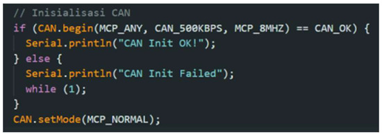
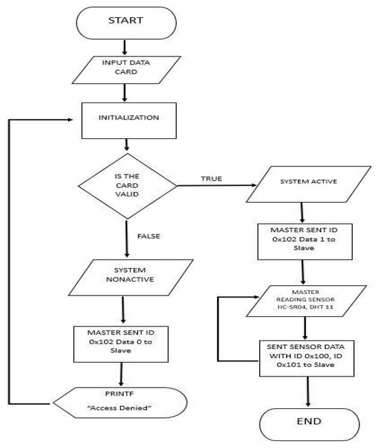
Figure 3.
Flowchart of operation algorithm for 4 kW fuel cell power source on stacked 20 units of 200 W each FC140-20 fuel cell.
3. Experimental Results and Discussion
Before the whole CAN system is developed for remote controlling and monitoring, the individual unit experiment must be formed first. The circuit diagram of the master (commander) node and a follower (slave) node is shown in Figure 4. The complete controlling and monitoring functions were developed based on the CAN message frame so that fuel cells are organized to produce a stacked output of rating powers.
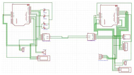
Figure 4.
Diagram of wiring Arduino UNO master and slave units to write and save the CAN message content as a complete controlling and monitoring function.
The individual controlling node comprises two Arduinos UNO via the MCP2515 breakout board for communicating as a CAN bus module. The “Arduino Write” (master) reads data from RC522 RFID sensors for authentication, ultrasonic sensors for interfering checks, DHT11 sensors for fuel cell temperature and humidity detection, and I2C LCD for data or important information display. The “Arduino Read” (slave) receives the data of the message frame sent over the CAN bus and controls devices such as an LCD warning message, servo driving for a cooling fan, and alert buzzer (Figure 5).
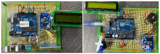
Figure 5.
All components assembled according to the designed circuit diagram.
The CAN bus is used as a platform to gain deeper insights into protocol-based communication signals through a PC-based LA. For logic signal analysis using Zeroplus Studio software, data transmitted via the CAN bus is captured and visualized, as shown in Figure 6. The decoding results include information such as message ID, sending time, and payload data. The data of the CAN message frame with Basic ID: 260 is sent with payload data 20, 181, 174, and 118. The transmission time analysis results confirmed that the signal met the specified timing parameters, with an average latency of 1.638 milliseconds.
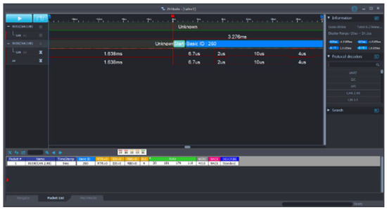
Figure 6.
Using Zeroplus Studio software for logic signal analysis via a PC-based LA.
The CAN system with RFID function can be easily implemented at the designated nodes located at different subsystems, i.e., System A or B, with various Arduino UNOs connected via the MCP2515 module (Figure 7). For example, one Arduino UNO functions as a data sender (“Arduino Write” or “Master”), integrating RFID sensors, and the other Arduino UNO serves as a data receiver (“Arduino Read” or “Slave”), displaying results on an I2C LCD, and it controlled devices such as servo fans for cooling. WiFi or Bluetooth were used for easy wireless monitoring and the buzzer alarm. Common issues, such as cable damage and MCP2515 detection errors, are addressed by implementing diagnostic routines in the Arduino C++ programming code. Diagnostic routines simplify setup and maintenance by allowing for quick hardware fault identification. This enhances system reliability and reduces downtime when repair or update is necessary. Therefore, the integration of diagnostic routines ensures optimal hardware performance and regular health monitoring for fuel cell power generation. The early detection of hardware failures in fuel cell systems significantly reduces maintenance time and operation costs and enhances a green energy power grid performance.
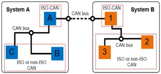
Figure 7.
Designated nodes located at different CAN subsystems.
4. Conclusions
The CAN bus with RFID interface effectively supports the integration of multiple sensors and actuators, showing high reliability at a bit rate of 500 kbps. It also enables stable and efficient communication in complex systems of 20 stacked fuel cells on each 200 W rated output, where quick and accurate data transfers minimize the risk of interference or latency. The LA tool linking Zeroplus Studio software provides important data on the CAN bus performance, facilitating debugging and optimization by enabling real-time signal monitoring and analysis. It helps engineers and developers fine-tune system parameters for increased efficiency and overall reliability in fuel cell operation. Finally, the concept of multi-node expansion can be considered to develop a more complex, multi-node configuration to enable broader, distributed communication between multiple devices based on the extended RFID or wireless interfaced CAN bus setup. The developed method in this study ensures greater scalability, flexibility, and potential applications in areas like industrial automation, autonomous vehicles, and smart green power grids.
Author Contributions
Conceptualization, F.-L.W. and C.-H.C.; methodology, F.-L.W.; software, C.-P.W.; validation, F.-L.W., C.-H.C. and C.-P.W.; formal analysis, F.-L.W.; investigation, F.-L.W.; resources, F.-L.W.; data curation, C.-H.C.; writing—original draft preparation, C.-P.W.; writing—review and editing, F.-L.W.; visualization, C.-H.C.; supervision, C.-H.C.; project administration, C.-H.C.; funding acquisition, F.-L.W. All authors have read and agreed to the published version of the manuscript.
Funding
This research was funded by the Taiwan Society of Professional Development in Vehicles, grant number TSPDV 20241029.
Institutional Review Board Statement
Not applicable.
Informed Consent Statement
Not applicable.
Data Availability Statement
No new data were created or analyzed in this study.
Acknowledgments
This paper is a complete version of the 2025 IEEE 5th International Conference on Electronic Communications, Internet of Things and Big Data (2025iceib.asia-conf). The conference paper can be reached at the DOI addres 10.3390/engproc2025108020.
Conflicts of Interest
Author Chu-Po Wen was employed by the company YAMAHA Motor R&D Taiwan Co., Ltd. The remaining authors declare that the research was conducted in the absence of any commercial or financial relationships that could be construed as a potential conflict of interest.
References
- Bozdal, M.; Samie, M.; Aslam, S.; Jennions, I. Evaluation of CAN Bus Security Challenges. Sensors 2020, 20, 2364–2380. [Google Scholar] [CrossRef] [PubMed]
- CAN in Automation, March 2023. Available online: www.can-cia.org (accessed on 14 March 2023).
- Bosch, R. CAN Specification Version 2.0; CAN in Automation: Stuttgart, Germany, 1991. [Google Scholar]
- Boys, R. CAN Primer: Creating Your Own Network; ARM Company, Ltd.: San Jose, CA, USA, 2009. [Google Scholar]
- Texas Instrument. Introduction to the Controller Area Network (CAN); SLOA101B–August 2002–Revised May 2016; Texas Instrument: Dallas, TX, USA, 2016. [Google Scholar]
- Watterson, C. Controller Area Network (CAN) Implementation Guide; Analog Devices, Inc.: Wilmington, MA, USA, 2017. [Google Scholar]
- Zeroplus Technology. CAN Bus Signal Analysis Using Zeroplus LA, Application Notes; Zeroplus Technology: New Taipei City, Taiwan, 2020. [Google Scholar]
- Le, Q.; Jiang, K.; Zhang, F. Design of automatic detection system for vehicle networking communication abnormal data based on CAN bus. Int. J. Infor. Comm. Tech. 2020, 6, 99–111. [Google Scholar] [CrossRef]
- Marei, M.I.; Samborsky, S.J.; Lambert, S.B.; Salama, M.M.A. On the Characterization of Ultracapacitor Banks Used for HEVs. In Proceedings of the IEEE Vehicle Power and Propulsion Conference (2006VPPC), Windsor, UK, 6–8 September 2006; pp. 1–6. [Google Scholar]
- Wen, F.-L.; Wen, S.-J.; Chan, C.-H.; Lu, H.-C. Error and Fault Detecting Study on Message Frames of Controller Area Network. In Proceeding of the 2024 Information Technology Application and Sustainable Environment Seminar (ITASES 2024), New Taipei City, Taiwan, 12 December 2024; pp. 108–112. [Google Scholar]
- Wen, P.-H.; Wen, F.-L.; Chan, C.-H.; Wen, S.-J. Identify Message Frame of Controller Area Network Using Arduino Chip Sets. In Proceeding of the 2024 Information Technology. Application and Sustainable Environment Seminar (ITASES 2024), New Taipei City, Taiwan, 12 December 2024; pp. 56–60. [Google Scholar]
- Lee, C.-Y.; Huang, R.-D.; Chuang, C.-W. Novel Integration Approach for In-Situ Monitoring of Temperature in Micro-direct Methanol Fuel Cell. Jpn. J. Appl. Phys. 2007, 46, 6911–6914. [Google Scholar] [CrossRef]
Disclaimer/Publisher’s Note: The statements, opinions and data contained in all publications are solely those of the individual author(s) and contributor(s) and not of MDPI and/or the editor(s). MDPI and/or the editor(s) disclaim responsibility for any injury to people or property resulting from any ideas, methods, instructions or products referred to in the content. |
© 2025 by the authors. Licensee MDPI, Basel, Switzerland. This article is an open access article distributed under the terms and conditions of the Creative Commons Attribution (CC BY) license (https://creativecommons.org/licenses/by/4.0/).