Abstract
The machine unit design for driving a specific work machine is a complex process, in which factors such as power machine type, power transmission drives, total efficiency coefficient, and total gear ratio determine an accurate model for calculating the drive. The correct choice of the above-described factors will lead to the construction of a machine unit with high performance while meeting the requirements of the client.
Keywords:
electric motor; gear ratio; reducer; coupling; efficiency coefficient; dimensions; graph; belt drive; chain gear drive; gears; worm drive 1. Introduction
The power transmission drive design of a given working machine in general mechanical engineering (belt conveyor, press, saw, elevator, pump, etc.) [1,2,3,4] in most cases begins with the required parameters such as power and revolutions per minute of the working machine. This, in turn, significantly limits the design activity and makes the task difficult to solve [5,6,7,8]. To facilitate the solution of this task, a method for selecting a machine unit (Figure 1) through graphical dependencies between the rotation frequency of the electric motor rotor, the weight and length of the electric motor, the total efficiency coefficient for the mechanical system, the total gear ratio of the drive, and the overall dimensions of the power machine are examined in this report [9]. The dependencies are derived separately:

Figure 1.
Machine unit.
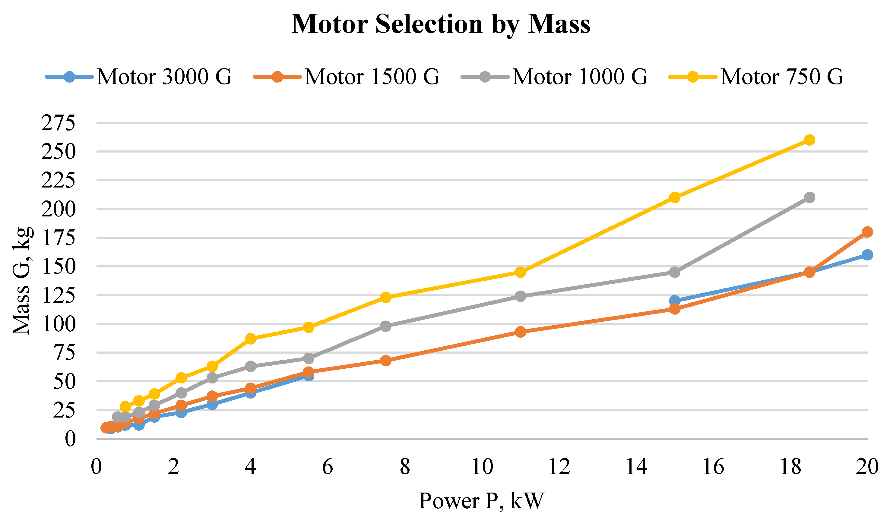
- electric motor mass as a function of its power—for motors with 750, 1000, 1500, and 3000 ;
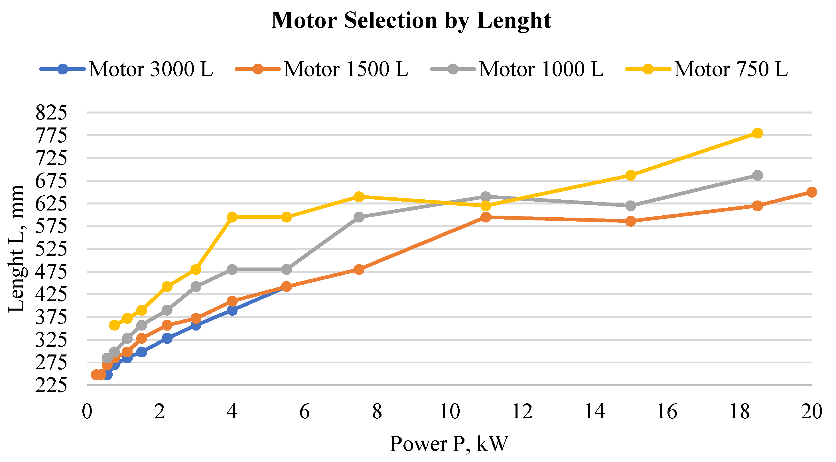
- the length of the electric motor as a function of its power—for motors with 750, 1000, 1500, and 3000 ;
- the total gear ratio of the drive as a function of the type of mechanical system;
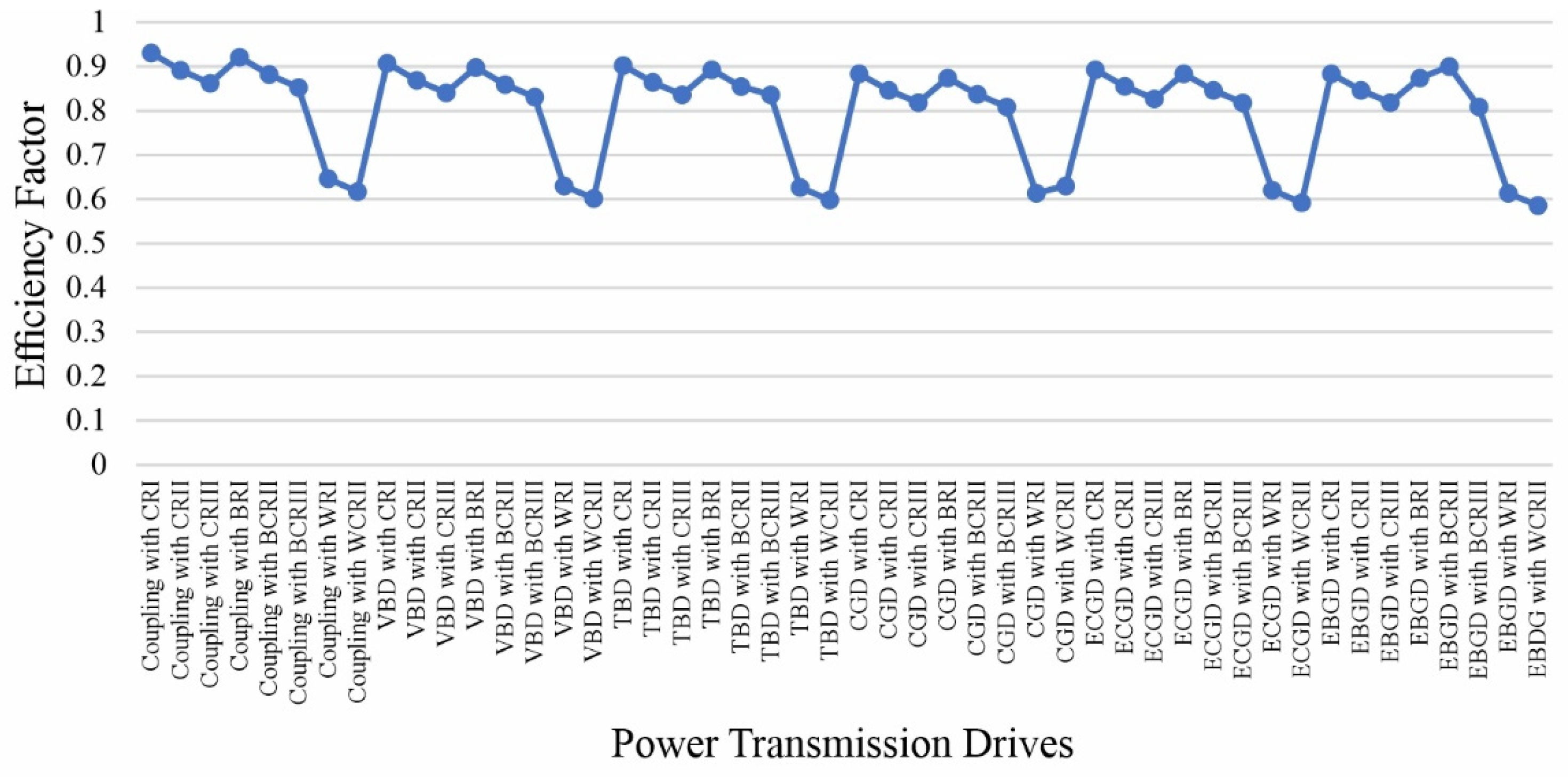
- the total efficiency coefficient of the drive as a function of the type of mechanical system.
When designing the machine unit, issues related to the selection of an electric motor are discussed, such as whether it will be from the group of 750, 1000, 1500, and 3000 rpm motors [10,11]; the selection of the machine unit mounting type, such as whether it will be a “Coupling” [12,13,14], “Belt drive”, “Chain drive”, etc.; and the selection of a gear reducer, such as whether it will be a “Single stage cylindrical reducer”, “Two stage bevel-cylindrical reducer, “Worm reducer”, etc. [15,16]. All these questions are answered when considering what gear ratio is required and what will be achieved with the individual unit selection. Along with the above, the following issues are also discussed: what efficiency coefficient will be obtained when choosing the drive and what size of the electric motor will be suitable to use in the system. Last but not least, the size of the selected gear reducer is monitored.
2. Materials and Methods
In some cases, the design of a machine unit can begin with the selection of an electric motor. To form the graphic dimensional dependencies of the electric motors, data for three-phase asynchronous motors from the groups of 750, 1000, 1500, and 3000 rpm motors are used [17]. The data for the length and weight of the electric motor are taken from company catalogs of Bulgarian manufacturers. The parameters can be changed depending on the machine availability on the relevant market, but the methodology for selecting a machine unit for driving a working machine remains the same.
Figure 2 shows the relationship , where G is the mass and P is the engine power. To better illustrate the above relationship, engines up to 20 kW are presented.
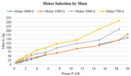
Figure 2.
Motor selection based on the mass.
The next relationship characterizing the overall dimensions of electric motors is , where L is the length of the motor. The relationship is presented again for motors with 750, 1000, 1500, and 3000 rev/min rotation frequency and up to 20 kW power (Figure 3).
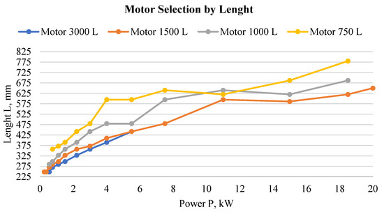
Figure 3.
Motor selection based on the length.
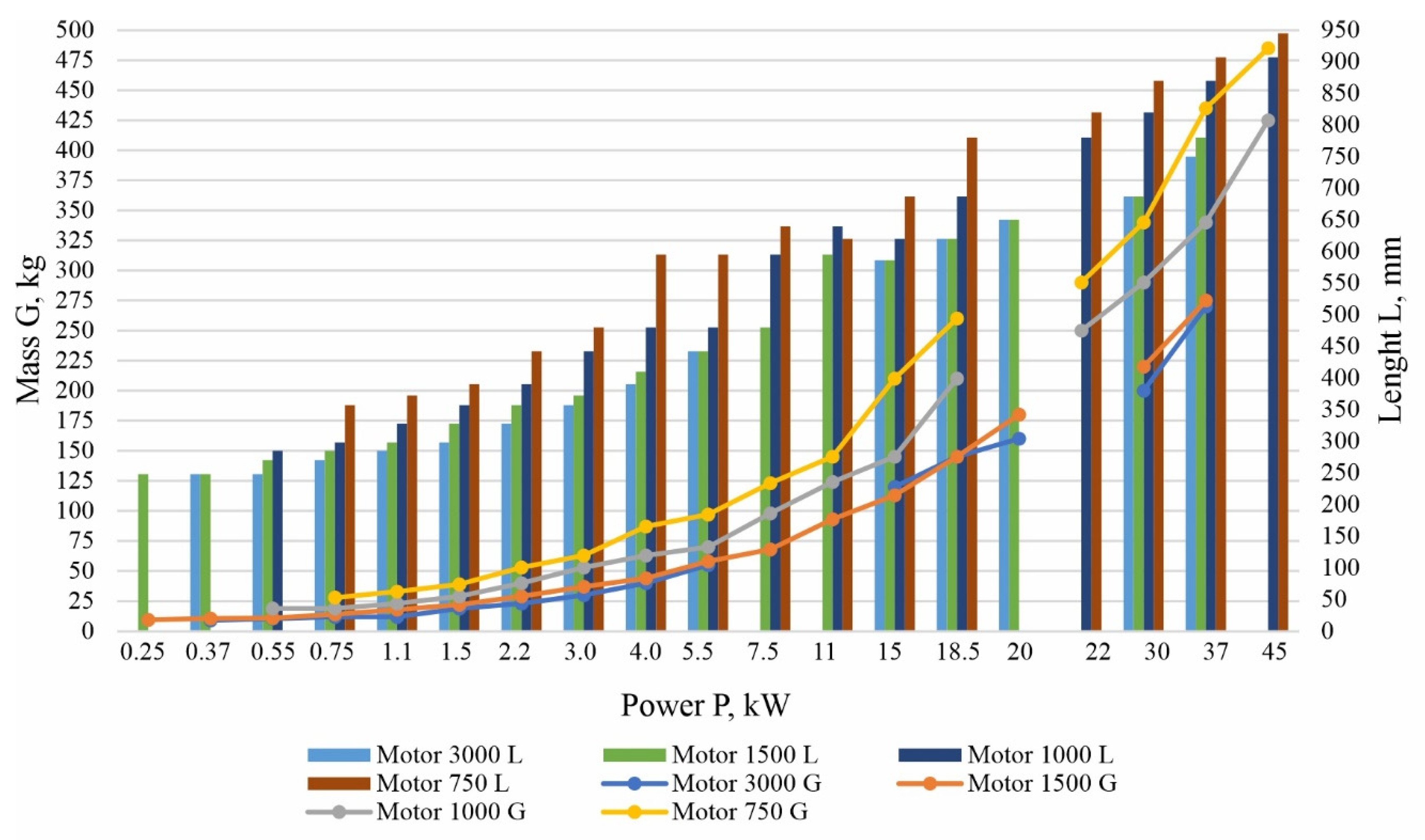
One of the main requirements when choosing a power transmission drive is the minimum size of the machine unit [18]. This, in turn, forces the designer to carefully select an electric motor based on size and weight. The following graph (Figure 4) summarizes the dependence of the weight and length of the electric motor in relation to its power and speed.
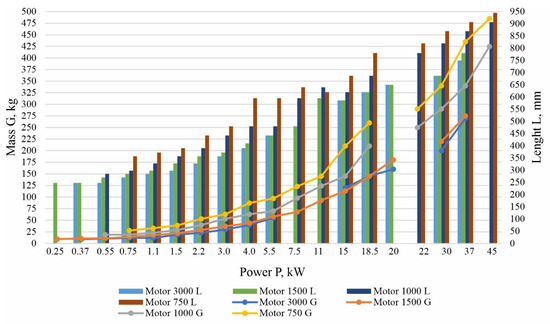
Figure 4.
Motor selection.
The first drive that will be considered is the coupling part. Here, a choice must be made between a coupling, VBD, TBD, CGD, ECGD, or EBGD [19]. The choice comes down to the following: what efficiency factor will be realized, what gear ratio is required, and what overall dimensions the connection link part has. The overall dimensions of the coupling part are a relative value since the location of this unit is individual for each project (e.g., the overall dimensions of the unit may remain the same when choosing a coupling or belt drive). For this reason, this parameter will not be considered.
Gear ratio data of the mounting type are shown in Table 1, including their efficiency coefficients with average values from the specified ranges in reference books like “The Design of Machine Elements” [20,21,22].

Table 1.
The ratio, dimension coefficient, and efficiency factor of the connecting link.
To select the next drive, which should reduce the speed and increase the torque for the working machine, a decision is made as to “what gear reducer to use” [23].
Table 2 shows the main gear reducer parameters that are most commonly used in mechanical engineering. The data present the parameters —the gear reducer ratio and efficiency coefficient, the latter being an average value from the specified range.

Table 2.
The ratio and efficiency factor of gear reducers.
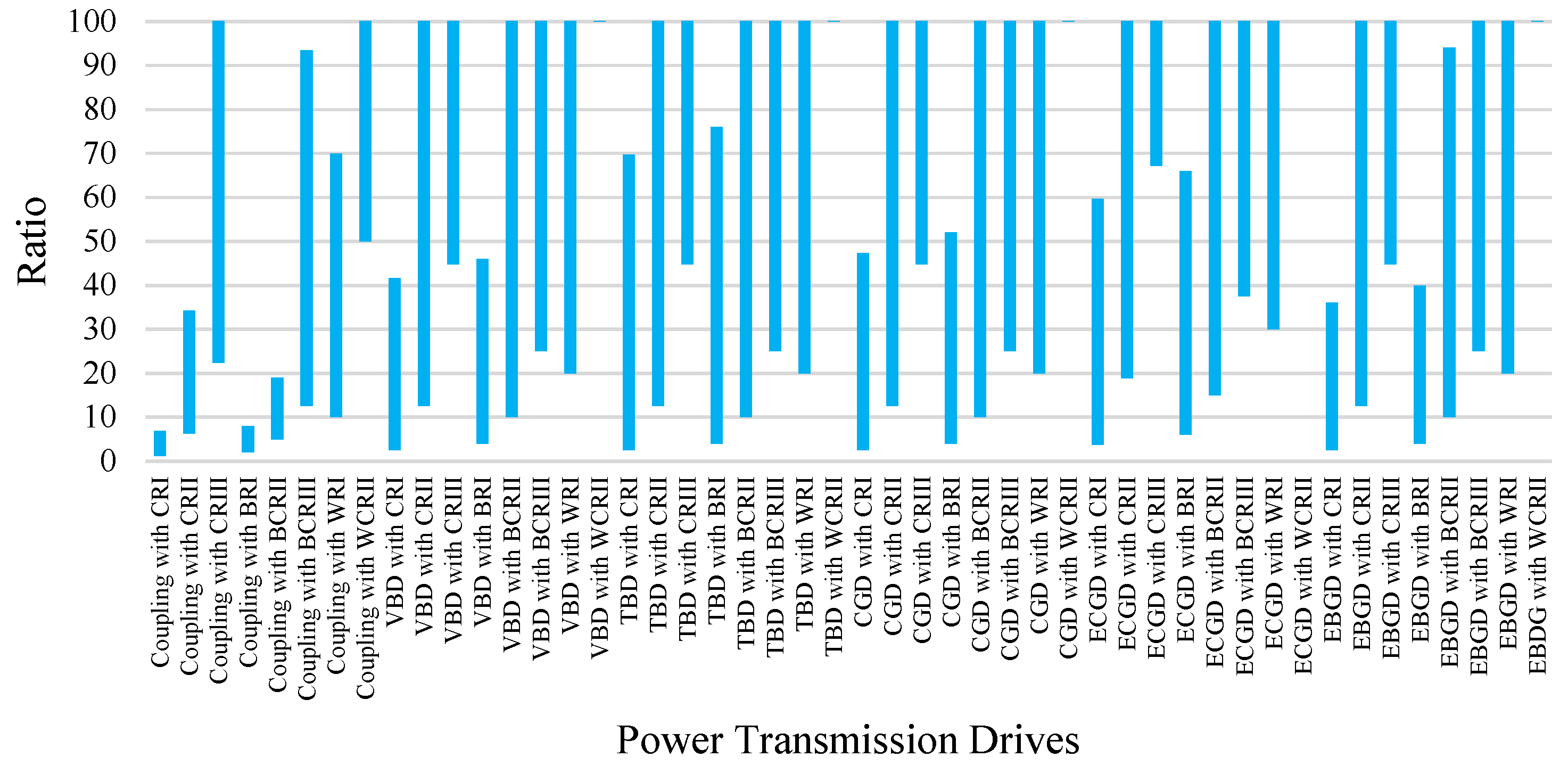
Because the efficiency coefficient of power transmission drives is and the gear ratio is , graphic relations and take on the form shown in Figure 5 and Figure 6.
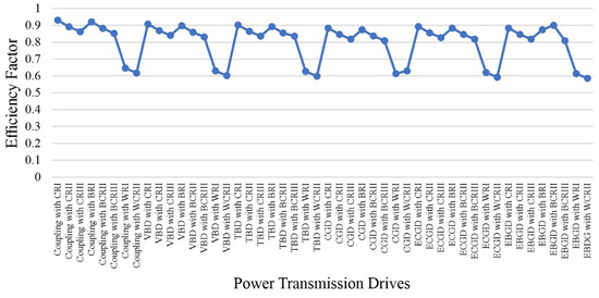
Figure 5.
Power transmission drives selection based on EF.
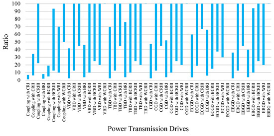
Figure 6.
Power transmission drives selection based on the ratio.
The bar graph in Figure 6 presents the gear ratio of various power transmission drives used in mechanical engineering. The maximum limit for gear ratio is 100 to better illustrate the relationship.
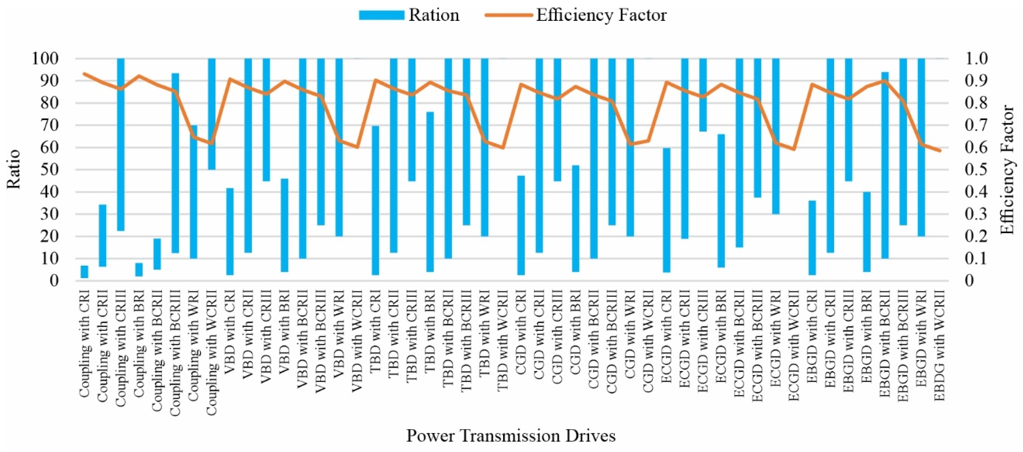
The graphical dependencies of Figure 5 and Figure 6 are interconnected with respect to the choice of a power transmission drive of a working machine. However, Figure 7 (presenting the summarized results) clearly shows the relationship between the most important parameters for a machine unit, namely, the power transmission drives efficiency and its gear ratio.
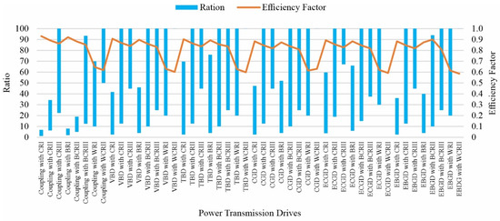
Figure 7.
Dependencies of power transmission drives—the efficiency factor and ratio.
Given the above, an example of a graphical selection methodology of a power transmission drive for a working machine can be provided.
Example: Company “X”, a leading manufacturer of coffee machines, wishes to increase its production activity by creating a new assembly line with maximum productivity for a new model of coffee machine. The new conveyor belt must be powered with and provided with a roll rotation speed .
Solution: From the given requirements for high productivity of company “X”, a preliminary assessment of the effectiveness of the system should be made. The graph in Figure 5 shows that a coupling with CRI (EC − ) and a coupling with BRI (EC − 2) have the highest efficiency. However, we should check whether their respective gear ratios will cover the required ratio of the revolutions of the electric motor and the working machine. The rotation speed ratio of the shafts is determined by the selected electric motor. The electric motor will be selected based on the minimum power.
where is the minimal power of the new conveyor belt, and is EC of the power transmission drives, but in this specific case it is and . From (1), minimal power is determined:
According to the calculations above, the most suitable electric motor for the working machine (conveyor belt) is the next largest in power from the minimum and , namely, 4000 W.
From the graph in Figure 4, we preliminarily choose to check the required gear ratio with electric motors from the 3000 and 1500 rpm motor groups since they are the smallest in terms of weight and overall dimensions. The gear ratios in both cases are as follows:
where is the gear ratio with 3000 rpm of the motor and is the gear ratio with 1500 rpm of the motor.
The gear ratios (4) and (5) are plotted on the graph in Figure 7 to determine whether the coupling with CRI and the coupling with BRI can provide this relationship. The analysis shows that the initial choice of power transmission drives is NOT suitable, but it is also seen from the graph that the next higher efficiency power transmission drive is suitable for achieving both gear ratios, which is VBD with CRI ().
3. Conclusions
The graphical selection method of a machine unit, used above, determines a quick and relatively accurate design solution for a working machine. With the help of two graphs and two preliminary calculations, a decision was made to select a machine unit that will meet the requirements for the necessary power and transmission ratio while, at the same time, meeting the condition for maximum productivity in terms of the achieved efficiency.
The summarized graphs in Figure 4 and Figure 7 are created based on the data collected from Bulgarian manufacturers of “Gear Reducers” and “Electric Motors” and give a clear picture of the parameters of overall dimensions, mass, gear ratio, and efficiency. In the same way, information on the overall dimensions and mass of the gear reducer and the mounting type can be applied in the present methodology. This way, the choice of the power transmission drives will be confirmed or refined for the relevant requirements of the “Contracting company”.
Funding
The paper was partially funded by NP7/2025 (TUV internal project funded by national budget). The author thanks colleagues from the university for their assistance.
Institutional Review Board Statement
Not applicable.
Informed Consent Statement
Informed consent was obtained from the study participant.
Data Availability Statement
The data presented in this study are available upon request from the corresponding author.
Conflicts of Interest
The author declare no conflicts of interest.
Abbreviations
The following abbreviations are used in this manuscript:
| VBD | V-belt drive |
| TBD | Toothed belt drive |
| CGD | Chain gear drive |
| ECGD | External Cylindrical Gear Drive |
| EBGD | External Bevel Gear Drive |
| CRI | Single Stage Cylindrical Reducer |
| CRII | Double Stage Cylindrical Reducer |
| CRIII | Triple Stage Cylindrical Reducer |
| BRI | Single Stage Bavel Reducer |
| BCRII | Double Stage Bevel Cylindrical Reducer |
| BCRIII | Triple Stage Bevel Cylindrical Reducer |
| WRI | Single Stage Worm Reducer |
| WCRII | Double Stage Worm Cylindrical Reducer |
| EF | Efficiency Factor |
References
- Jiang, T.; Wang, Z.; Ren, Z.; Liu, G.; Ren, F. Analysis on mechanical characteristics of brake wheel and brake shoe of elevator traction machine. J. Phys. Conf. Ser. 2021, 2125, 012046. [Google Scholar] [CrossRef]
- Gazor, H.R.; Roustapour, O.R. Comparison of mechanical Z-shape elevator operation for handling seed corn. Agric. Eng. Int. CIGR J. 2021, 23, 271–278. [Google Scholar]
- Gavryukov, A.; Kolesnikov, M.; Sikorsky, I.; Zapryvoda, A.; Volters, A.; Samoilenko, M. Devising a procedure for calculating the belt tension of a conveyor with a stopped drive when changing the transportation length. East.-Eur. J. Enterp. Technol. 2025, 133, 22. [Google Scholar] [CrossRef]
- Polishchuk, L.; Piontkevych, O.; Burdeinyi, M.; Trehubov, V. Justification for choosing the type of belt conveyor drive. Bull. Mech. Eng. Transp. 2024, 1, 115–122. [Google Scholar] [CrossRef]
- Bufalari, L.; Anselmi, E.; Rinchi, M.; Howard, K.; Talluri, L.; Fiaschi, D. Mechanical design and manufacture of a boundary layer pump. E3S Web Conf. 2023, 414, 03016. [Google Scholar] [CrossRef]
- Soares, J.D.; Paula, M.O.; Carneiro, A.C.O.; Costa, L.J.; Oliveira, A.C.; Pereira, B.L.C. Parameters to determine mechanical strength of charcoal in a hydraulic press. Rev. Bras. De Ciências Agrárias 2021, 16, e9096. [Google Scholar] [CrossRef]
- Babenko, D.; Dotsenko, N.; Gorbenko, O. Study of structural and kinematic characteristics of an energy-efficient oil press. Ukr. Black Sea Reg. Agrar. Sci. 2024, 28, 41–54. [Google Scholar] [CrossRef]
- Ding, Y.; Zhang, C.; Ruan, C.; Tong, C.; Ruan, J. Study on mechanical efficiency of 65 ml/r fuel pump and its piston optimization. Adv. Mech. Eng. 2023, 15, 1–15. [Google Scholar] [CrossRef]
- Yaghoubi, M.; Tavakoli, H. Mechanical Design of Machine Elements by Graphical Methods; Springer: Cham, Switzerland, 2022; Volume XV, 285p, ISBN 978-3-031-04328-4. [Google Scholar] [CrossRef]
- Rika, S.; Hristovska, E.; Chalamani, S.; Sovreski, Z.; Stavreva, S.; Kuzmanov, I. Analysis and Optimization of Electric Motor Power for Rubber Belt Conveyors. Int. Trans. J. Eng. Manag. Appl. Sci. Technol. 2025, 16, 1. [Google Scholar] [CrossRef]
- Prasetia, A.M.; Sartika, L.; Samanta, R.; Sanjaya, D. Implementation of Variable Speed Drive as Starting Control of Three Phase Induction Motor. J. Edukasi Elektro 2024, 8, 2. [Google Scholar] [CrossRef]
- Li, W.; Chai, Z.; Wang, M.; Hu, X.; Guo, Y. Online Identification and Verification of the Elastic Coupling Torsional Stiffness. Shock Vib. 2016, 2016, 2016432. [Google Scholar] [CrossRef]
- Zhao, B.; Zhao, Y.; Feng, J.; Peng, X. Numerical and experimental investigation of the torsional stiffness of flexible disc couplings. Int. J. Mech. Sci. 2016, 114, 207–216. [Google Scholar] [CrossRef]
- Hristov, H.; Tenev, S.; Mehmedov, I.; Bankova, A. Hysteresis Energy Caracteristic of SEGME-type in Flexible Coupling. In Proceedings of the 4th International Conference on Communications, Information, Electronic and Energy Systems, CIEES 2023, Plovdiv, Bulgaria, 23–25 November 2023; pp. 1–6. [Google Scholar] [CrossRef]
- Dinh, V.-T.; Tran, H.-D.; Tran, Q.-H.; Vu, D.-B.; Vu, D.; Vu, N.-P.; Nguyen, T.-T. Multi-Objective Optimization of a Two-Stage Helical Gearbox Using MARCOS Method. Designs 2024, 8, 53. [Google Scholar] [CrossRef]
- Danh, T.; Thanh, D.; Danh, B.; Cuong, N.; Tung, L. Optimization of a Two-stage Bevel Helical Gearbox using Multiple Objectives to Increase Efficiency and Reduce Gearbox Bottom Area. WSEAS Trans. Appl. Theor. Mech. 2024, 19, 11. [Google Scholar] [CrossRef]
- Elprom. Available online: https://www.elprommotors.com/en (accessed on 10 April 2025).
- Spektor, M. Machine Design Elements and Assemblies; Industrial Press, Inc.: South Norwalk, CT, USA, 2018; 480p, ISBN 978-0831136192. [Google Scholar]
- Tiruneh, A. Introduction for Designing Machine Element: Machine Design; LAP LAMBERT Academic Publishing: Saarbrücken, Germany, 2020; 60p. [Google Scholar]
- Rodrigues, S. Machine Elements; Discovery Publishing House (India): New Delhi, India, 2024; 254p. [Google Scholar]
- Rajkumar, E.; Bikash, R. Basic Elements of Machine Design; Namya Press: Delhi, India, 2024; 333p. [Google Scholar]
- Childs, P.; Masen, M. Mechanical Design Engineering Handbook, Butterworth-Heinemann, 3rd ed.; Elsevier: London, UK, 2024; 880p, ISBN 9780443220777. [Google Scholar]
- Modul PLC. Available online: https://www.modul-biala.com/en/ (accessed on 10 April 2025).
Disclaimer/Publisher’s Note: The statements, opinions and data contained in all publications are solely those of the individual author(s) and contributor(s) and not of MDPI and/or the editor(s). MDPI and/or the editor(s) disclaim responsibility for any injury to people or property resulting from any ideas, methods, instructions or products referred to in the content. |
© 2025 by the author. Licensee MDPI, Basel, Switzerland. This article is an open access article distributed under the terms and conditions of the Creative Commons Attribution (CC BY) license (https://creativecommons.org/licenses/by/4.0/).


