Review and Comparative Analysis of Modern Knee Prostheses with Development of a Conceptual Design †
Abstract
1. Introduction
2. Review of Modern Knee Prostheses
2.1. Industrial Systems Overview and Academic Research
- –
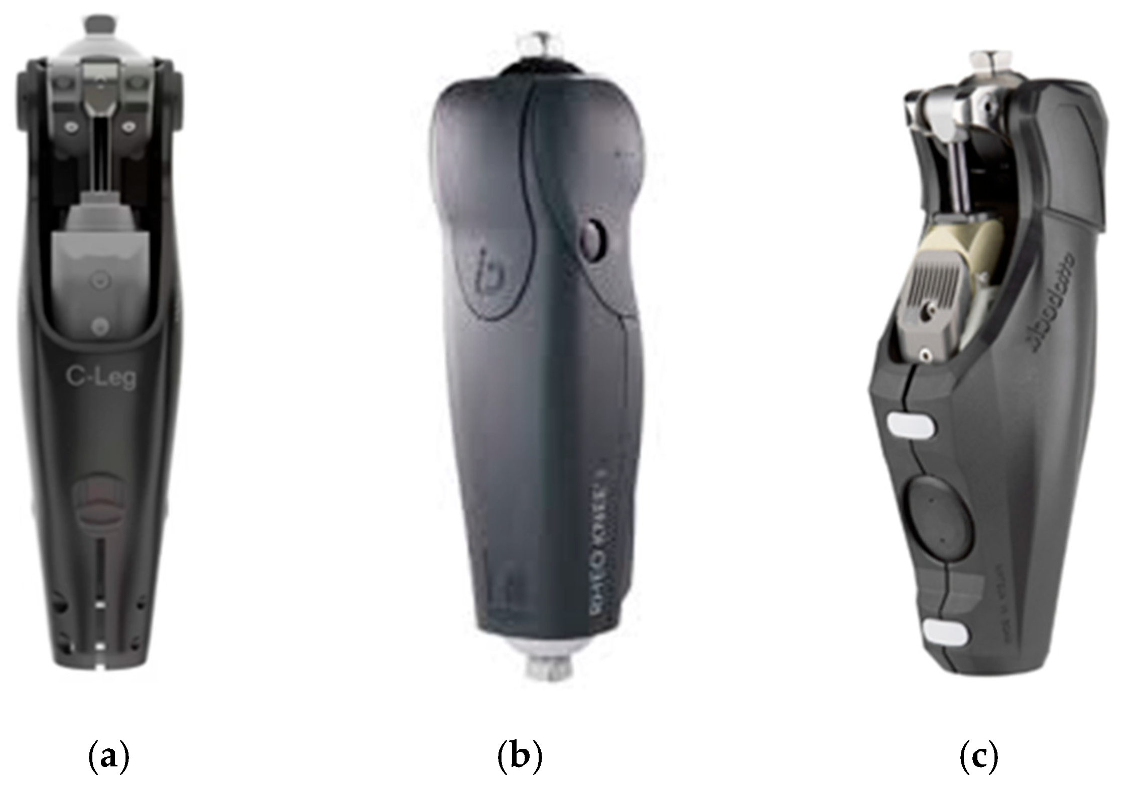
- Genium X3 (Ottobock)—This knee prosthesis integrates a hydraulic system, multi-sensor feedback, and Bluetooth-based smartphone control. It stands out as a high-precision, fully waterproof prosthesis capable of operating in aquatic environments [4].
- –
- Rheo Knee (Össur)—A sensor-driven knee prosthesis utilizing adaptive control algorithms. It automatically detects the user’s gait pattern and adjusts the joint stiffness accordingly [5].
- –
- C-Leg (Ottobock)—Designed for elderly individuals or those with low mobility, this safety-oriented prosthesis is equipped with intelligent control systems [6].
2.2. Comparative Analysis
2.3. Strengths and Limitations of Existing Solutions
- –
- Passive prostheses are characterized by structural simplicity, energy efficiency, and low cost. They generally offer high reliability and require minimal maintenance.
- –
- Microprocessor-controlled prostheses are capable of adapting to dynamic conditions. For instance, hydraulic systems can automatically adjust damping levels based on walking speed, improving the user’s gait stability.
- –
- Some modern systems are capable of integrating early stance flexion (ESF) and swing resistance functions within a single device, enhancing gait naturalness and reducing impact forces during walking.
- –
- Limited adaptability to the environment: Passive knee systems often struggle on uneven terrain (e.g., stairs, slopes), while some microprocessor solutions rely on monocentric designs that may not fully replicate natural joint movement.
- –
- Restricted recognition of user intent: Passive systems cannot directly interpret the user’s motion intention. They only respond to parameters such as joint angle, force, or acceleration detected via sensors, limiting real-time adaptation to spontaneous movement.
- –
- Latency in finite state machine (FSM)-based control strategies: These systems operate based on previous gait data, which may cause delays (hysteresis) in responding to the current state of motion.
- –
- EMG (electromyography)-based control still presents significant challenges due to weak signal strength, high noise levels, and the limited muscular activity of residual limbs. As such, EMG is not yet reliable for fully independent control.
- –
- Short lifespan and poor technical adaptability: Many current knee prostheses tend to fail within 3–5 years of use. When one component malfunctions, the entire system may need replacement, resulting in additional financial burden for the user.
3. Materials and Methods
3.1. Development of a Conceptual Design
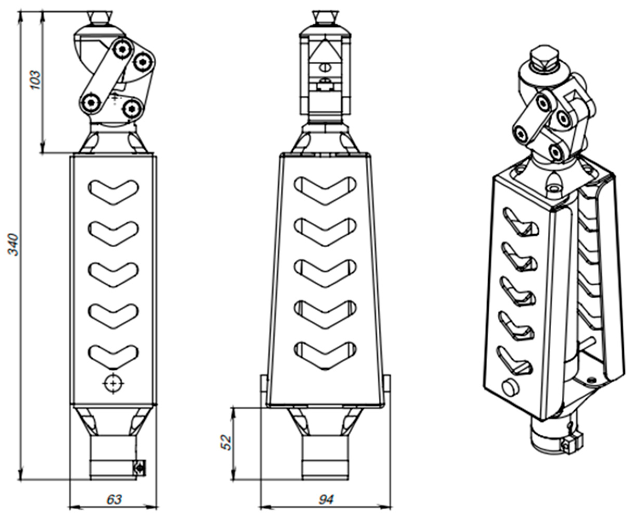
- –
- Upper joint (hinge) mechanism
- –
- Central load-bearing body
- –
- Lower mounting interface module
- –
- Total height: 340 mm
- –
- Upper joint unit height: 108 mm
- –
- Central body width (front view): 63 mm
- –
- Maximum width (rear view): 94 mm
- –
- Lower section height: 52 mm
- –
- Modularity—allows integration with different control units or damping systems
- –
- Lightweight and durable—achieved through structural material selection and geometric optimization
- –
- Adaptive architecture—kinematics and geometry tailored to human motion
- –
- Manufacturing flexibility—suitable for CNC machining and 3D printing
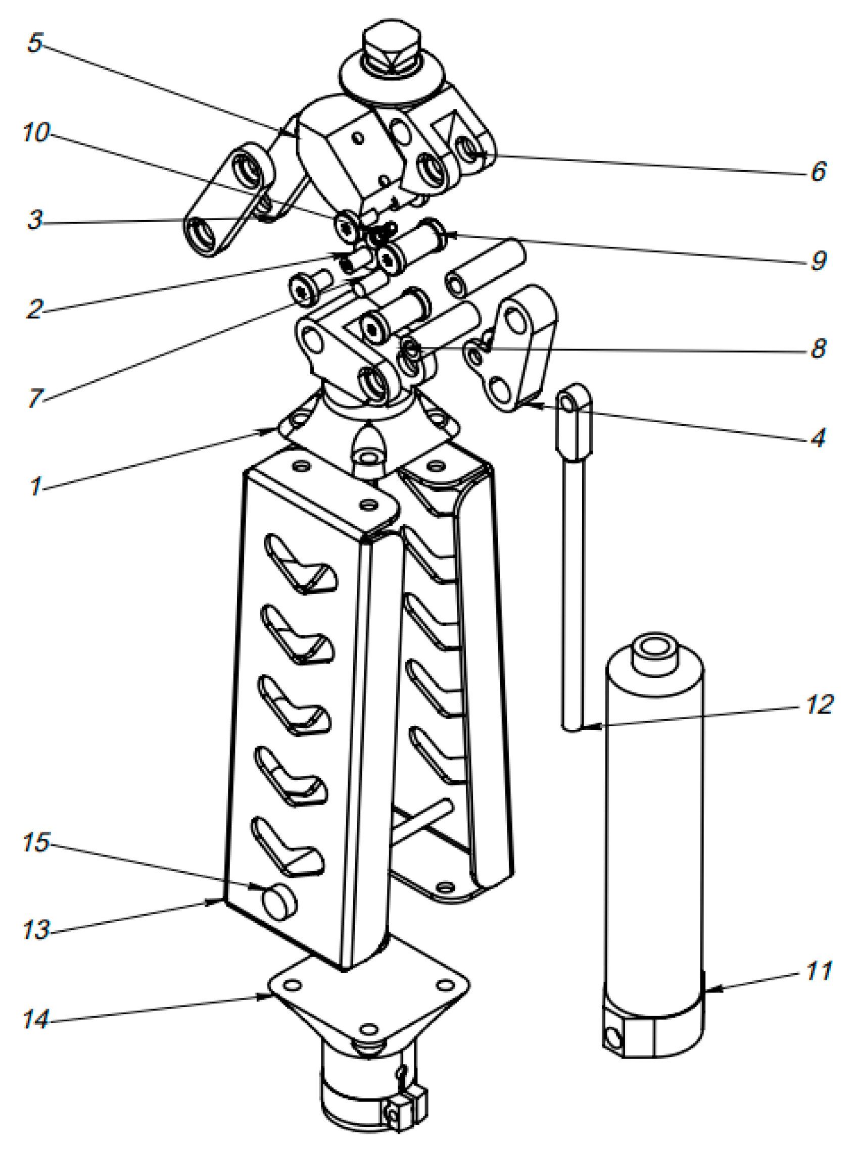
3.2. Semi-Exploded View of the Assembled Conceptual Prosthesis
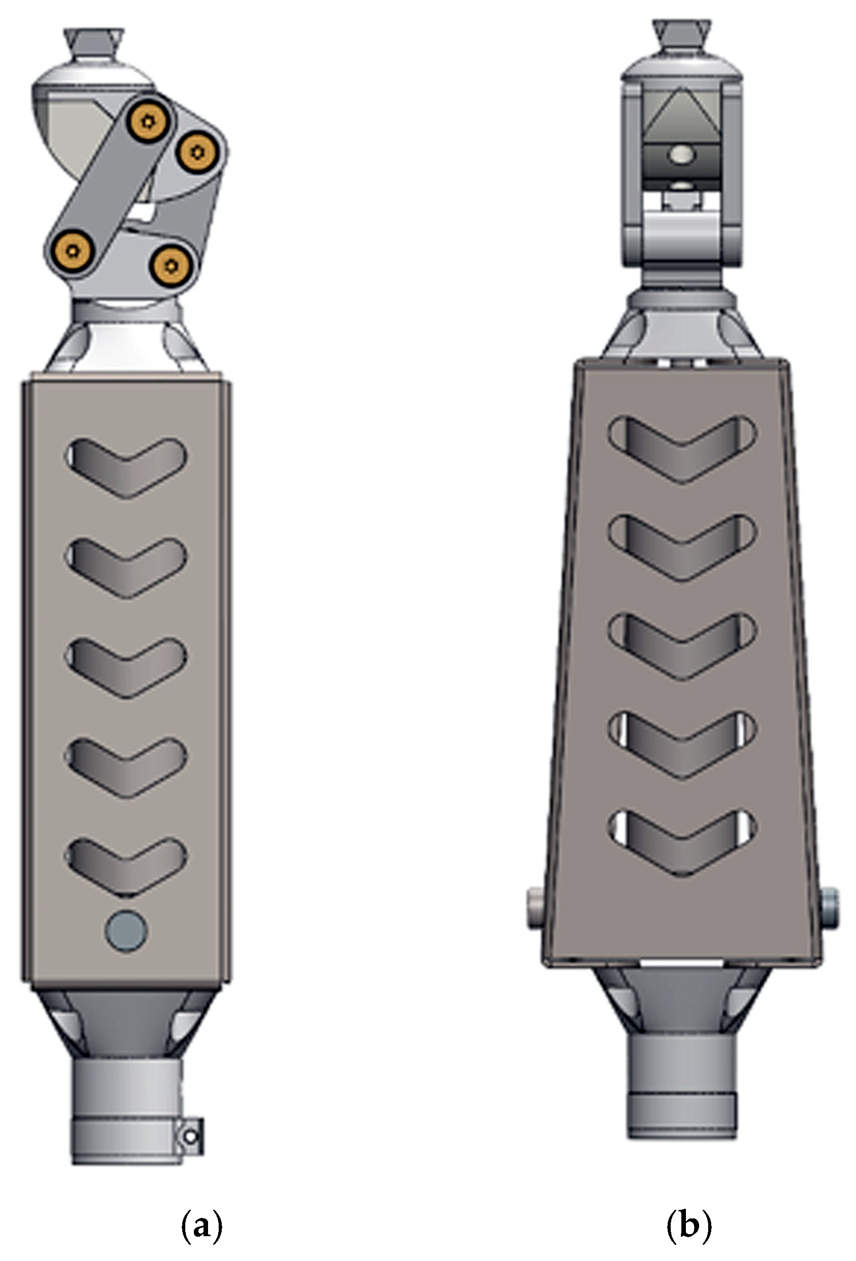
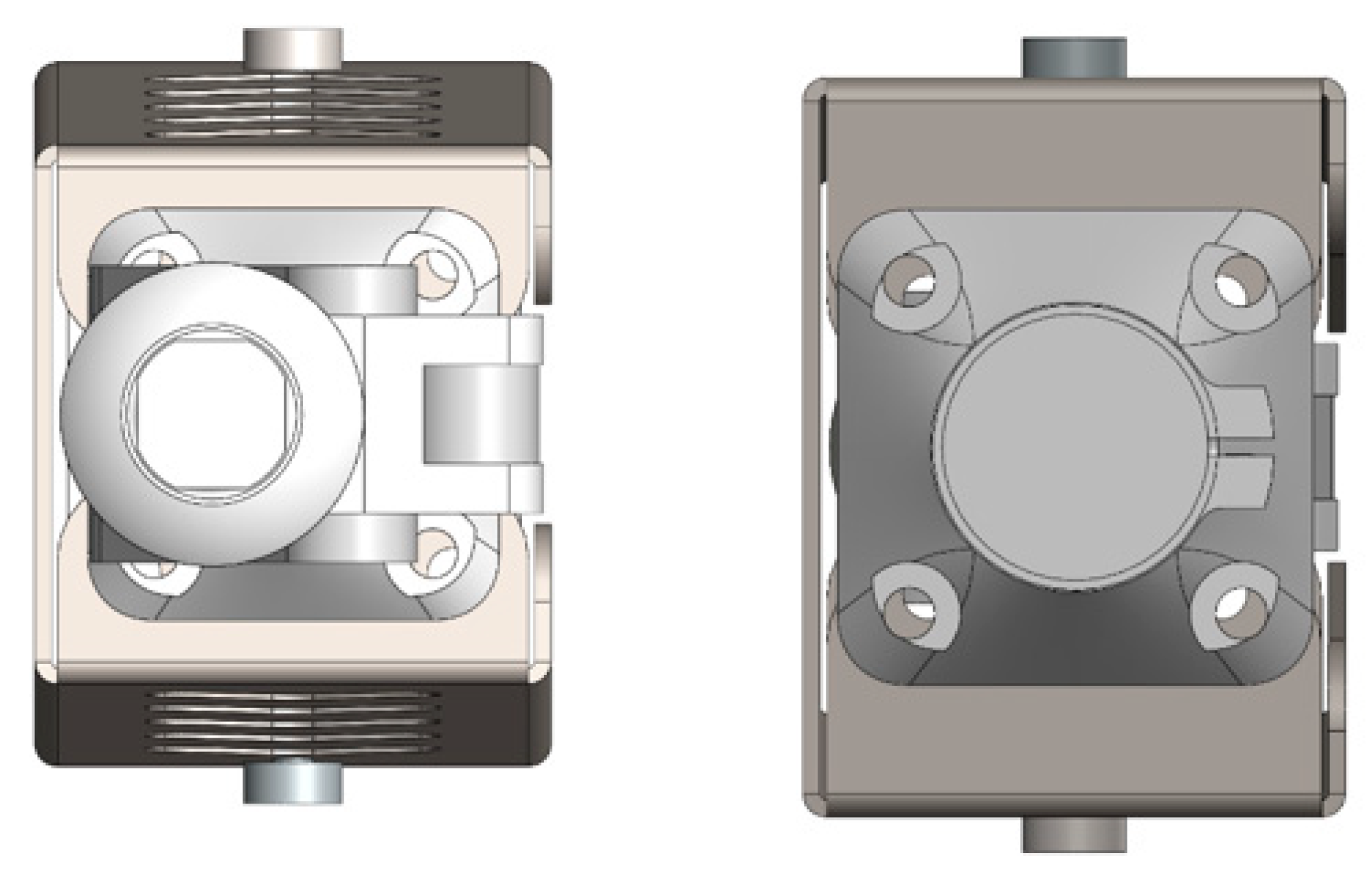
3.3. Three-Dimensional Model of the Assembled Knee Prosthesis (General View and Lower Interface)
- –
- The side projection clearly shows the eccentric elements and joint axes.
- –
- The front projection displays symmetrical cutouts in the central body, designed to reduce weight and enhance the esthetic appearance.
- –
- The left-side view shows a rendered model with material properties visualized.
- –
- The right-side view represents a technical projection emphasizing geometric specifications.
- –
- The external geometry of the prosthesis is designed for compatibility with CNC machining or 3D printing;
- –
- The interface dimensions comply with ISO standards for modular prosthetic integration;
- –
- The modular connection between the joint block and lower flange allows for easy repair and component replacement;
- –
- The dual-perspective layout reveals the precise geometry and level of mechanical integration within the structure.
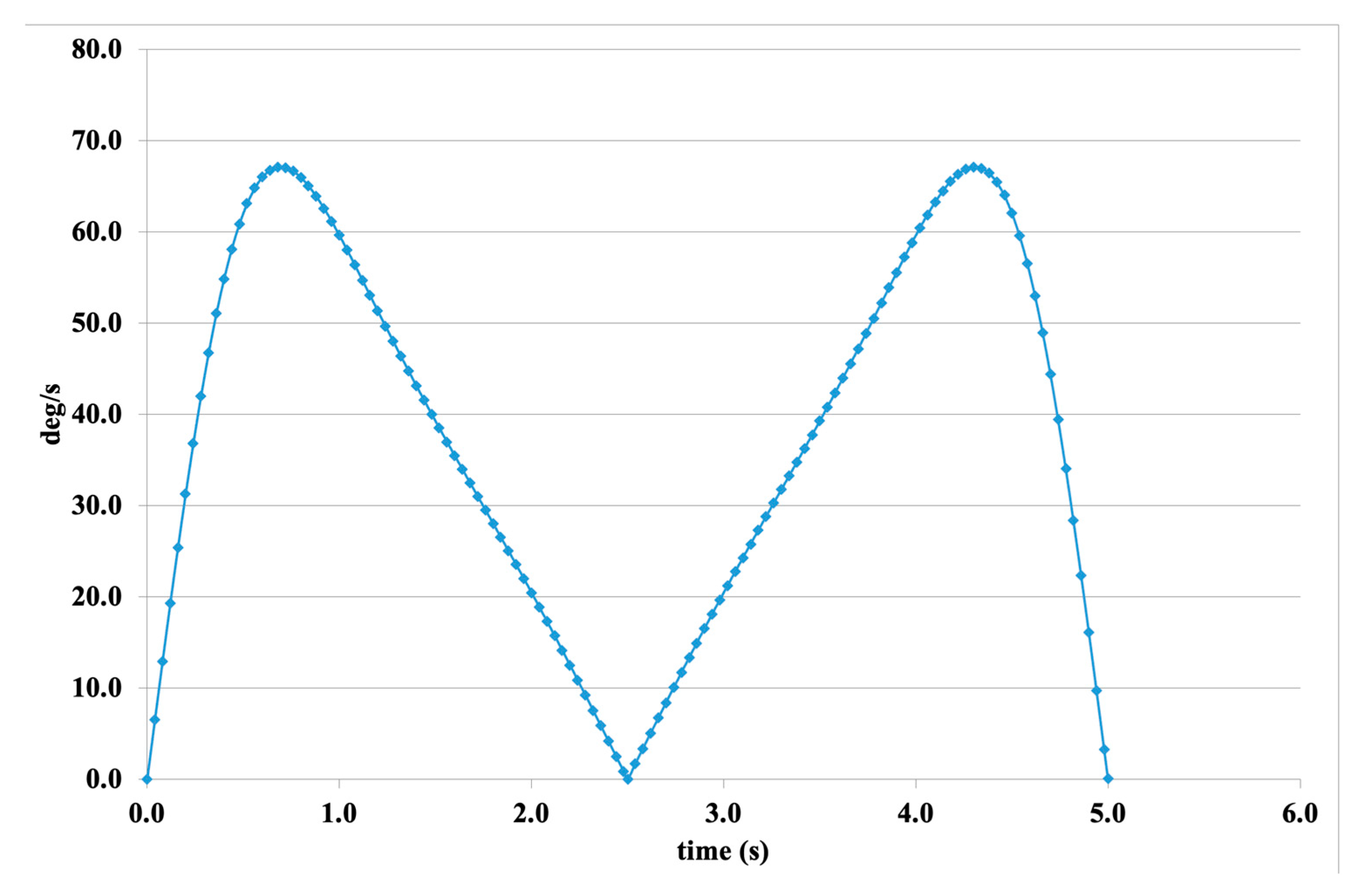
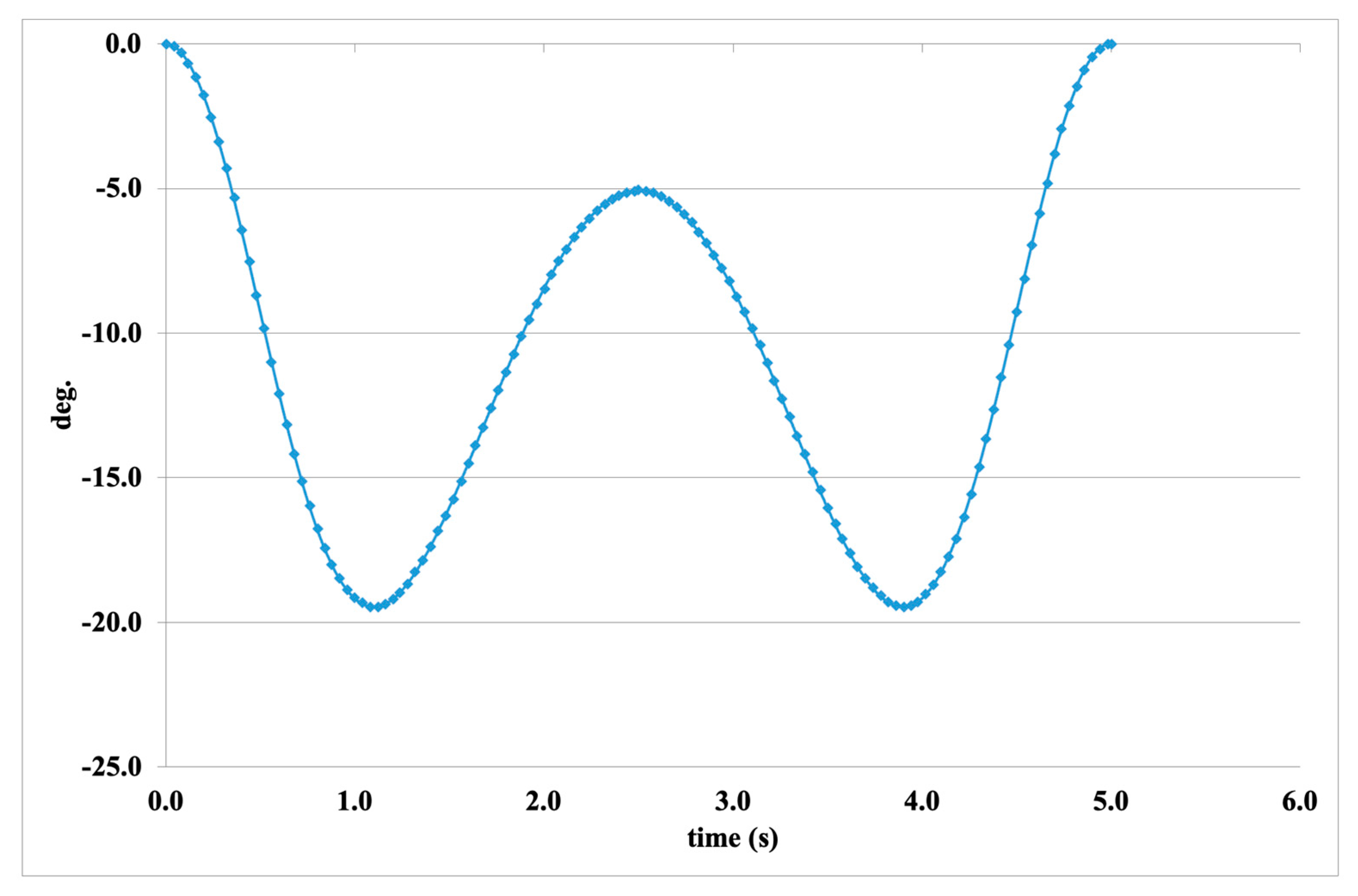
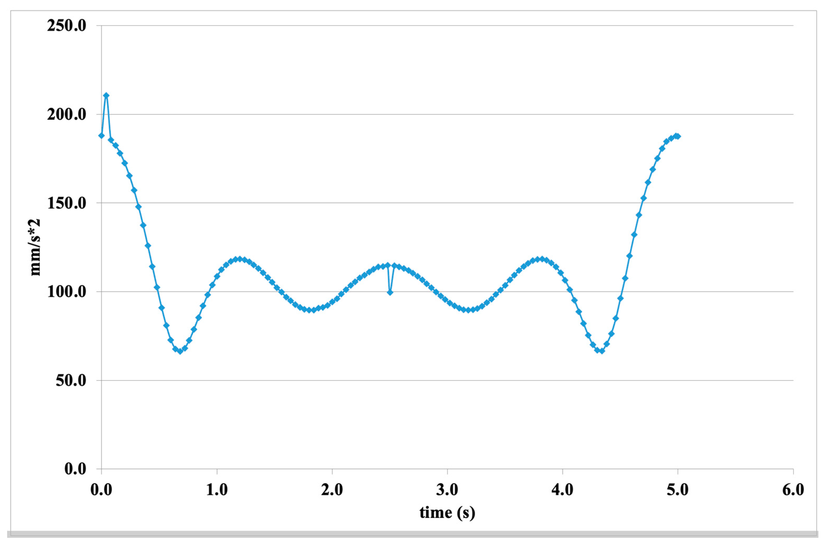
3.4. Simulation and Motion Analysis Results
- –
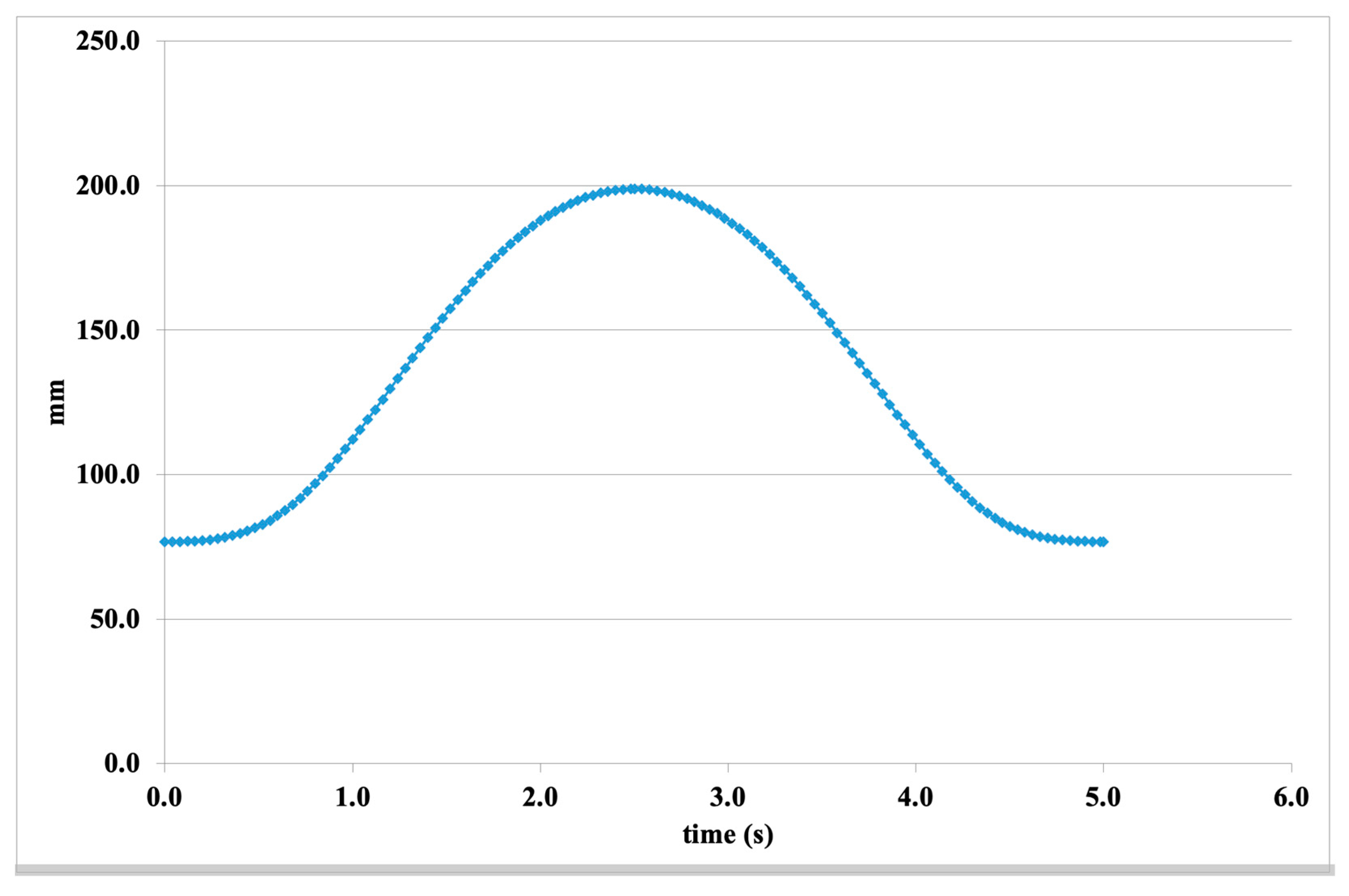
- Natural movement behavior (as seen in the angular displacement curve)
- –
- Stability and repeatability (cycle symmetry)
- –
- Dynamic response (velocity and acceleration values)
- –
- Effective range of motion (linear displacement)
3.5. Static Structural Analysis Results
- –
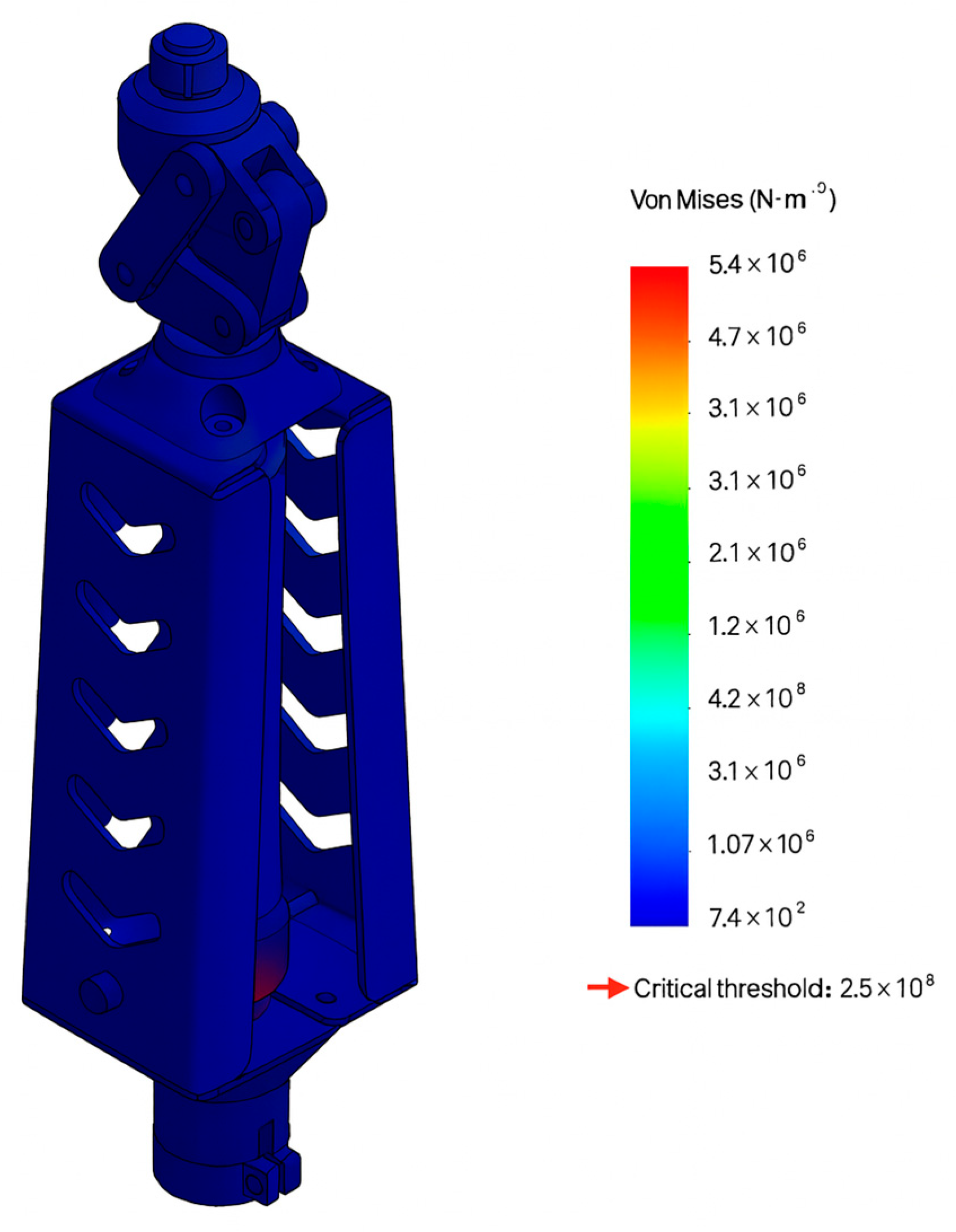
- Mesh quality was adequate for reliable result interpretation.
- –
- Stress concentration was observed in localized areas but remained within safety margins for the majority of the structure.
- –
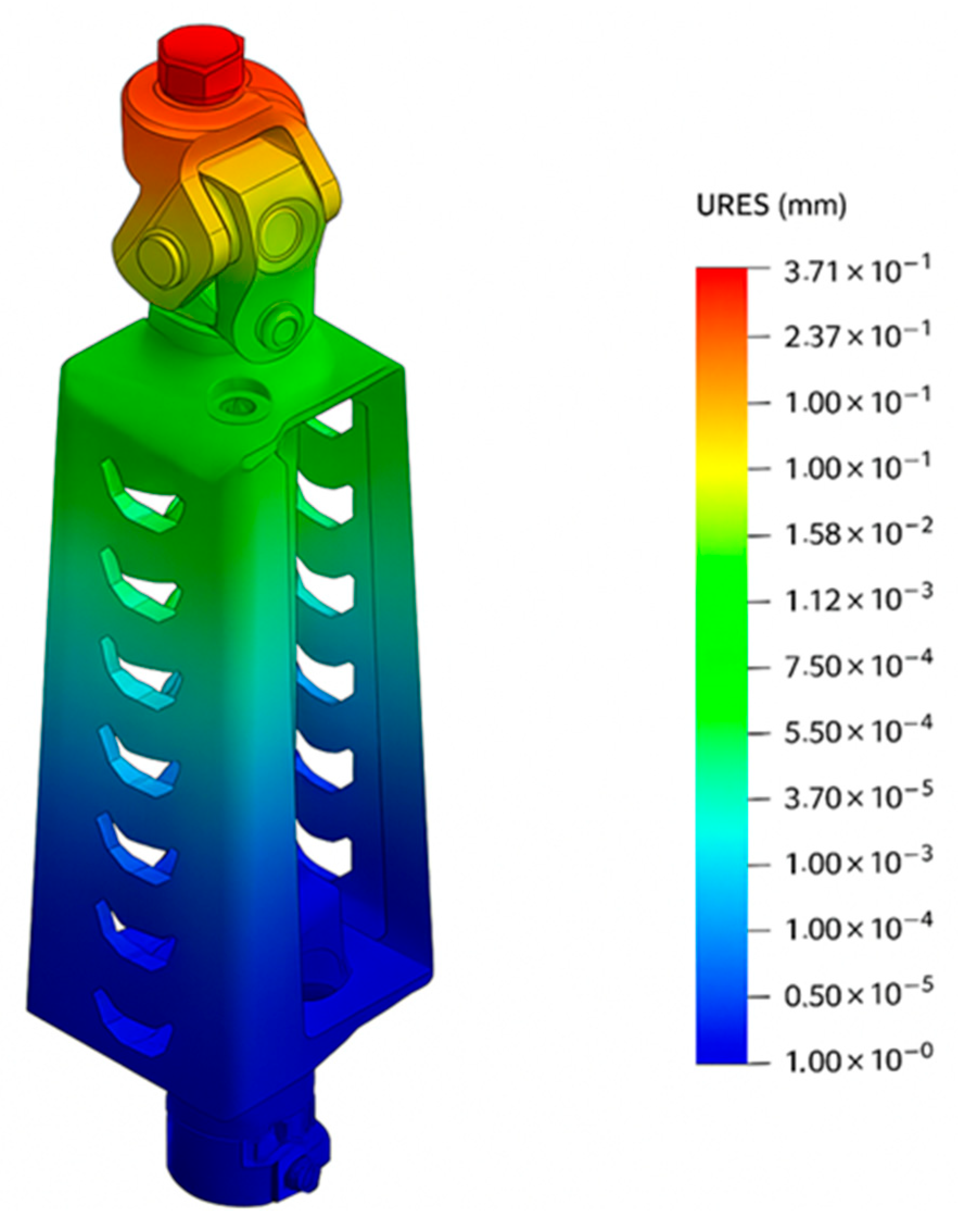
- Displacement values were minimal (≤0.375 mm), confirming the high stiffness of the design.
- –
- Strain was primarily present in the upper joint, with negligible deformation in the main load-bearing body.
3.6. Boundary Conditions and Simulation Setup
- –
- Analysis type—Linear static, without time-dependent or dynamic stress variations.
- –
- Material—Aluminum alloy 6061-T6 (Kaiser Aluminum, Foothill Ranch, California, USA), known for its high strength-to-weight ratio and suitability for both CNC machining and 3D printing.
- –
- Contact type—All mating components were assigned bonded (fixed) contacts, which restrict relative motion or sliding. This simplification is appropriate for the initial stage of structural evaluation.
- –
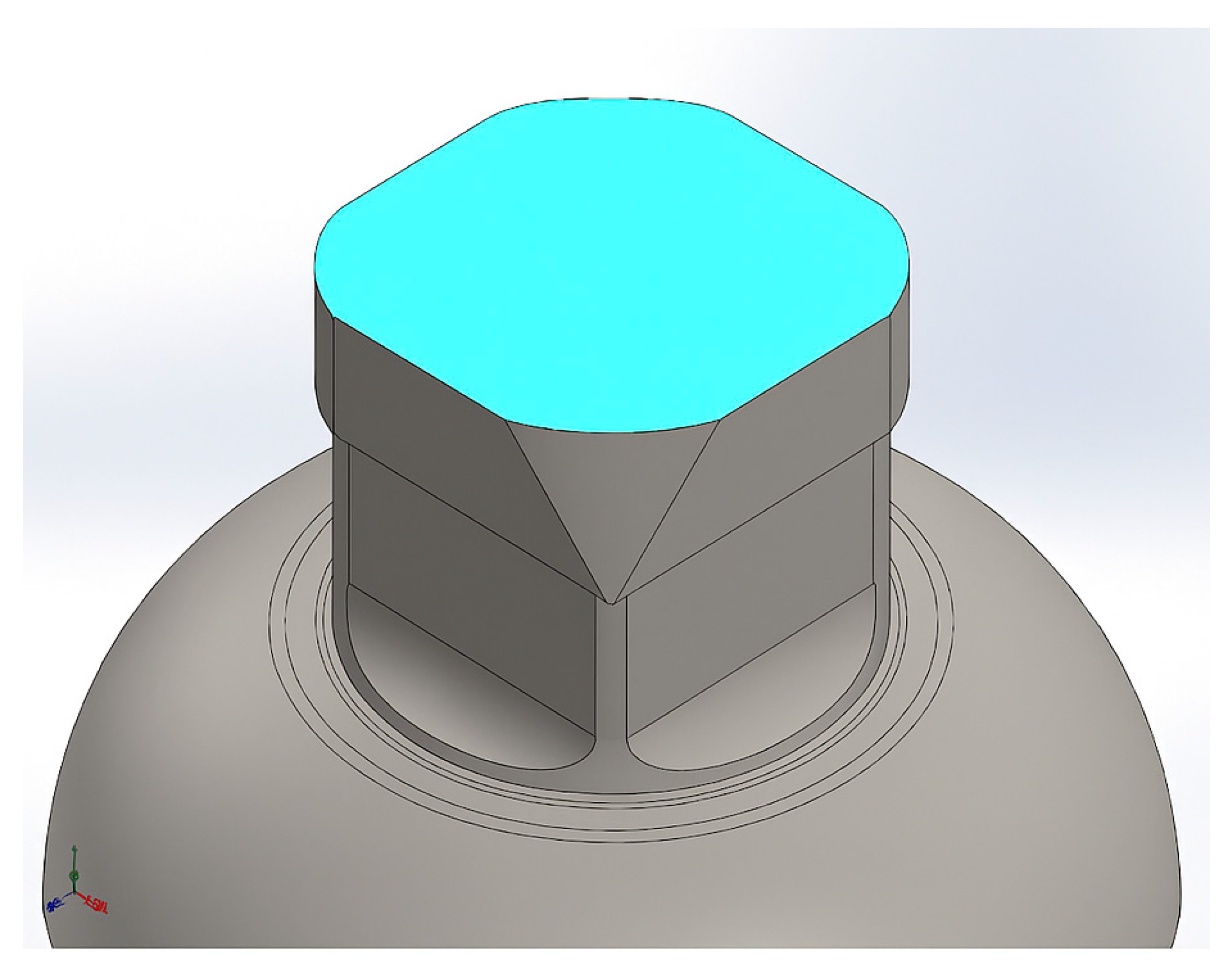
- Fixtures—The bottom mounting surface of the prosthesis was fully constrained in all degrees of freedom, simulating a rigid fixation to a support surface.
- –
- Load—A vertical force of 800 N was applied at the upper hinge joint, representing the body weight of an 80 kg user under static conditions.
- –
- Coordinate system—A Cartesian coordinate system was used, with the Z-axis oriented vertically downward (in the direction of gravitational force).
4. Future Work and Research Directions
- –
- Passive spring-damper foot without electric actuation: This system is based on spring elements and passive shock absorption mechanisms. It connects to the ankle module via an adapter and provides energy-free adaptation to ground conditions.
- –
- Autonomous active ankle joint: This 2 DoF module operates in both the sagittal and transverse planes and is equipped with an intelligent control system. It is integrated with either the knee or foot structures through a ball-and-socket platform (BSP).
- –
- Phase one: The initial prototype will be fabricated using PLA plastic through 3D printing to evaluate dimensional accuracy and basic mechanical compatibility.
- –
- Phase two: Based on the outcomes of initial functional testing, a revised version will be produced using high-strength thermoplastics (such as PETG, ABS, or nylon) or lightweight aluminum alloys (e.g., AlSi10Mg or 6061-T6) to verify load-bearing performance.
- –
- Final phase: The final version of the prosthesis will be manufactured using AISI 304 stainless steel, applying either Selective Laser Melting (SLM) metal 3D printing or high-precision CNC machining, to ensure durability, corrosion resistance, and biomechanical reliability.
- –
- The modular construction allows easy assembly and disassembly for testing;
- –
- Each module is removable and replaceable as needed;
- –
- Knee, ankle, and foot modules can be freely combined via an adapter;
- –
- Full adaptation to the patient’s clinical condition facilitates rehabilitation and daily use.
5. Conclusions
Author Contributions
Funding
Institutional Review Board Statement
Informed Consent Statement
Data Availability Statement
Conflicts of Interest
References
- Liang, W.; Qian, Z.; Chen, W.; Song, H.; Cao, Y.; Wei, G.; Ren, L.; Wang, K.; Ren, L. Mechanisms and component design of prosthetic knees: A review from a biomechanical function perspective. Front Bioeng. Biotechnol. 2022, 10, 950110. [Google Scholar] [CrossRef] [PubMed]
- Qadir, M.U.; Haq, I.U.; Khan, M.A.; Shah, K.; Chouikhi, H.; Ismail, M.A. Design, Analysis, and Development of Low-Cost State-of-the-Art Magnetorheological-Based Microprocessor Prosthetic Knee. Sensors 2024, 24, 255. [Google Scholar] [CrossRef] [PubMed]
- Cho, B.W.; Hong, H.-T.; Koh, Y.-G.; Park, K.K.; Kang, K.-T. Comparative Study on Three Different Designs of Locking Mechanisms in Total Knee Arthroplasty. Bioengineering 2025, 12, 169. [Google Scholar] [CrossRef] [PubMed]
- Genium X3. 2025. Available online: https://www.ottobock.com/ru-ex/product/3B5-3 (accessed on 17 March 2025).
- Rheo Knee. 2025. Available online: https://www.ossur.com/en-us/prosthetics/knees/rheo-knee (accessed on 17 March 2025).
- C-Leg 4. 2025. Available online: https://www.ottobock.com/en-us/product/3C88-3-3C98-3-22923 (accessed on 19 April 2025).
- Martinez-Villalpando, E.C.; Herr, H. Agonist-antagonist active knee prosthesis: A preliminary study in level-ground walking. J. Rehabil. Res. 2009, 46, 361–373. [Google Scholar] [CrossRef]
- Lambrecht, B.G.A.; Kazerooni, H. Design of a semi-active knee prosthesis. In Proceedings of the IEEE International Conference on Robotics and Automation, Kobe, Japan, 12–17 May 2009; pp. 639–645. [Google Scholar] [CrossRef]
- Park, J.; Yoon, G.H.; Kang, J.W.; Choi, S.B. Design and control of a prosthetic leg for above-knee amputees operated in semi-active and active modes. Smart Mater. Struct. 2016, 25, 085009. [Google Scholar] [CrossRef]
- Lenzi, T.; Cempini, M.; Hargrove, L.; Kuiken, T. Design, development, and testing of a lightweight hybrid robotic knee prosthesis. Int. J. Rob. Res. 2018, 37, 953–976. [Google Scholar] [CrossRef]
- Murthy Arelekatti, V.N.; Winter, V.A.G. Design and preliminary field validation of a fully passive prosthetic knee mechanism for users with transfemoral amputation in India. J. Mech. Robot. 2018, 10, 1. [Google Scholar] [CrossRef]
- Okuda, M.; Nakaya, Y. Prosthetic Limbs with Means Capable of Reducing Torque in the Initial Period of Bend of Knee Joint. U.S. Patent No 8,529,634 B2, 10 September 2013. [Google Scholar]
- Arelekatti, V.N.M.; Winter, A.G.; Dorsch, D.S. Passive Artificial Knee. U.S. Patent No 10,405,997 B2, 10 September 2019. [Google Scholar]
- Grohs, T.; Schuh, A.; Bremer, M. Damper System. U.S. Patent No 17/312,380, 10 December 2019. [Google Scholar]
- Biomechanics of Knee Stability Control with Four-Bar Prosthetic Knees. Available online: https://rehabtech.com.au/techguide/pdf/kneeControl.pdf (accessed on 17 March 2025).
- Berringer, M.A.; Boehmcke, P.J.; Fischman, J.Z.; Huang, A.Y.; Joh, Y.; Warner, J.C. Modular design of a passive, low-cost prosthetic knee mechanism to enable able-bodied kinematics for users with transfemoral amputation. In Proceedings of the ASME Design Engineering Technical Conference, Cleveland, OH, USA, 6–9 August 2017. [Google Scholar] [CrossRef]
- Mohanty, R.K.; Mohanty, R.C.; Sabut, S.K. A Systematic Review on Design Technology and Application of Polycentric Prosthetic Knee in Amputee Rehabilitation. Phys. Eng. Sci. Med. 2020, 43, 781–798. [Google Scholar] [CrossRef] [PubMed]
- Arelekatti, V.N.M.; Winter, A.G. Design of a fully passive prosthetic knee mechanism for transfemoral amputees in India. In Proceedings of the IEEE International Conference on Rehabilitation Robotics, Singapore, 11–14 August 2015; pp. 350–356. [Google Scholar] [CrossRef]
- Uzbekbayev, A.; Zhetenbayev, N.; Sultan, A.; Ozhikenov, K.; Iliev, T.; Sergazin, G. Design and Operation Requirements for a Foot and Ankle Prosthesis. In Proceedings of the 2024 5th International Conference on Communications, Information, Electronic and Energy Systems (CIEES), Veliko Tarnovo, Bulgaria, 20–22 November 2024; pp. 1–5. [Google Scholar] [CrossRef]



| Criteria | Industrial Models | Research Prototypes |
|---|---|---|
| Price | Very high ($30,000–$100,000+) | Low ($1000–$5000) |
| Technology | Mature, commercialized | Experimental, sometimes manually controlled |
| Ergonomics | User-adapted, esthetic | Mainly for laboratory use |
| Feedback System | Fully integrated (sensors, AI) | Basic or external module-based |
| Target User | Patients and clinical environments | Research laboratories and educational institutions |
| Prosthesis Model | Structure Type | ESF Activation Method | Phase Adaptation | Key Features |
|---|---|---|---|---|
| Blatchford ESK+ | Single-axis + ESF | Weight-activated | Stance phase only | Simple and reliable system |
| (Arelekatti et al. [18]) | Locking axis + ESF | GRF-triggered | Locked during stance phase | Spring-assisted return mechanism |
| Ottobock 3R60 | 5 bar linkage | Resistance-based flexion | Adapts to stance and swing | High adaptability |
| Össur Total-2000 | 7 bar linkage | Buffered limit flexion | Smooth transition during phases | Enhanced shock absorption |
| Function | Mechanism Type | Commercial Examples | Research Prototypes |
|---|---|---|---|
| Stability | Weight-brake, Lock | OT-3R49, OS-OP4, BL-Mercury | NA-Hybrid |
| ESF | ESF linkage | OT-3R80, Össur Total-2000 | MIT-Knee-1 |
| Swing Resistance | Hydraulic damper | OS-OH7, TL-X6 | MIT-Knee-2 |
| No. | Component Name |
|---|---|
| 1 | Main load-bearing body |
| 2 | Upper bracket block |
| 3 | Lateral support element |
| 4 | Push link arm |
| 5 | Upper attachment point |
| 6 | Rotational joint axis |
| 7 | Multi-link mechanism block |
| 8 | Support linkage |
| 9 | Auxiliary mounting bracket |
| 10 | Lateral bracket support |
| 11 | Lower interface connector |
| 12 | External damping element |
| 13 | Screw holes |
| 14 | Lower connecting plate |
| 15 | Load-bearing axis fixture |
| Parameter | Value |
|---|---|
| Total motion cycle time | 5 s |
| Angular displacement range | –19° to 0° |
| Peak angular velocity | ≈67°/s |
| Angular velocity pattern | Sinusoidal, with two cycles |
| Peak linear acceleration | ≈211 mm/s2 |
| Linear displacement range | 76.7 mm to 198.9 mm |
| Motion pattern | Smooth, cyclic movement similar to natural gait |
| Property | Value | Units |
|---|---|---|
| Elastic modulus (Young’s modulus), E | 68.9 | GPa |
| Poisson’s ratio, ν | 0.33 | – |
| Yield strength | 276 | MPa |
| Ultimate tensile strength | 310 | MPa |
| Density | 2.70 | g/cm3 |
| Allowable strain (max) | 0.002 | – |
| Brinell hardness | 95 | HB |
| Elongation at break | 12 | % |
Disclaimer/Publisher’s Note: The statements, opinions and data contained in all publications are solely those of the individual author(s) and contributor(s) and not of MDPI and/or the editor(s). MDPI and/or the editor(s) disclaim responsibility for any injury to people or property resulting from any ideas, methods, instructions or products referred to in the content. |
© 2025 by the authors. Licensee MDPI, Basel, Switzerland. This article is an open access article distributed under the terms and conditions of the Creative Commons Attribution (CC BY) license (https://creativecommons.org/licenses/by/4.0/).
Share and Cite
Sayat, A.; Nursultan, Z.; Yerkebulan, N.; Aidos, S.; Arman, U.; Gani, S.; Kassymbek, O.; Asset, N. Review and Comparative Analysis of Modern Knee Prostheses with Development of a Conceptual Design. Eng. Proc. 2025, 104, 80. https://doi.org/10.3390/engproc2025104080
Sayat A, Nursultan Z, Yerkebulan N, Aidos S, Arman U, Gani S, Kassymbek O, Asset N. Review and Comparative Analysis of Modern Knee Prostheses with Development of a Conceptual Design. Engineering Proceedings. 2025; 104(1):80. https://doi.org/10.3390/engproc2025104080
Chicago/Turabian StyleSayat, Akhmejanov, Zhetenbayev Nursultan, Nurgizat Yerkebulan, Sultan Aidos, Uzbekbayev Arman, Sergazin Gani, Ozhikenov Kassymbek, and Nurmangaliyev Asset. 2025. "Review and Comparative Analysis of Modern Knee Prostheses with Development of a Conceptual Design" Engineering Proceedings 104, no. 1: 80. https://doi.org/10.3390/engproc2025104080
APA StyleSayat, A., Nursultan, Z., Yerkebulan, N., Aidos, S., Arman, U., Gani, S., Kassymbek, O., & Asset, N. (2025). Review and Comparative Analysis of Modern Knee Prostheses with Development of a Conceptual Design. Engineering Proceedings, 104(1), 80. https://doi.org/10.3390/engproc2025104080


