Proceeding Paper

Ensuring Accuracy in Turning †

Department of Machine Tools and Manufacturing, University of Ruse, 7017 Ruse, Bulgaria
Presented at the 14th International Scientific Conference TechSys 2025—Engineering, Technology and Systems, Plovdiv, Bulgaria, 15–17 May 2025.
Eng. Proc. 2025, 100(1), 14; https://doi.org/10.3390/engproc2025100014
Published: 4 July 2025

Abstract

At the stage of the final processing of surfaces, the quality indicators of the surfaces of parts—size, shape in cross-section and longitudinal section, mutual arrangement of surfaces, and roughness—are obtained. This includes technical and organizational measures and activities that are laid down or taken into account in the applied technology. This publication constructs cause-and-effect diagrams of the factors influencing the achievement of each of these accuracy indicators. Ways to reduce the negative impact of some factors are indicated. Errors related to the components of the technological system are analyzed and grouped. Tasks related to accurate process design are defined. Guidelines related to structural accuracy design are given. The technological conditions for ensuring the accuracy of finishing operations when processing parts by turning are formulated.

1. Introduction

The modern machining of parts in mechanical engineering is characterized by the widespread use of digital technologies, encompassing not only equipment but also the design, management, and organization of technological processes. This trend is dictated by the desire to increase their efficiency while maintaining the quality of the respective products in order to meet the growing demands of consumers [1,2,3]. In order to manage technological processes, it is necessary to have in-depth knowledge of the factors that influence them at the individual stages of process implementation—design, implementation under real production conditions, and processing of the batch of parts (the established production process).
The subject of this publication is the obtainment of the quality indicators of surfaces—the accuracy of size, shape in cross- and longitudinal sections, mutual arrangement of surfaces, and roughness. This is carried out at the final stage of processing the relevant surfaces by turning. Ensuring these quality indicators and maintaining them over time is a prerequisite for increasing the competitiveness of enterprises and the economy of production, with a properly selected factor to influence.

2. Materials and Methods
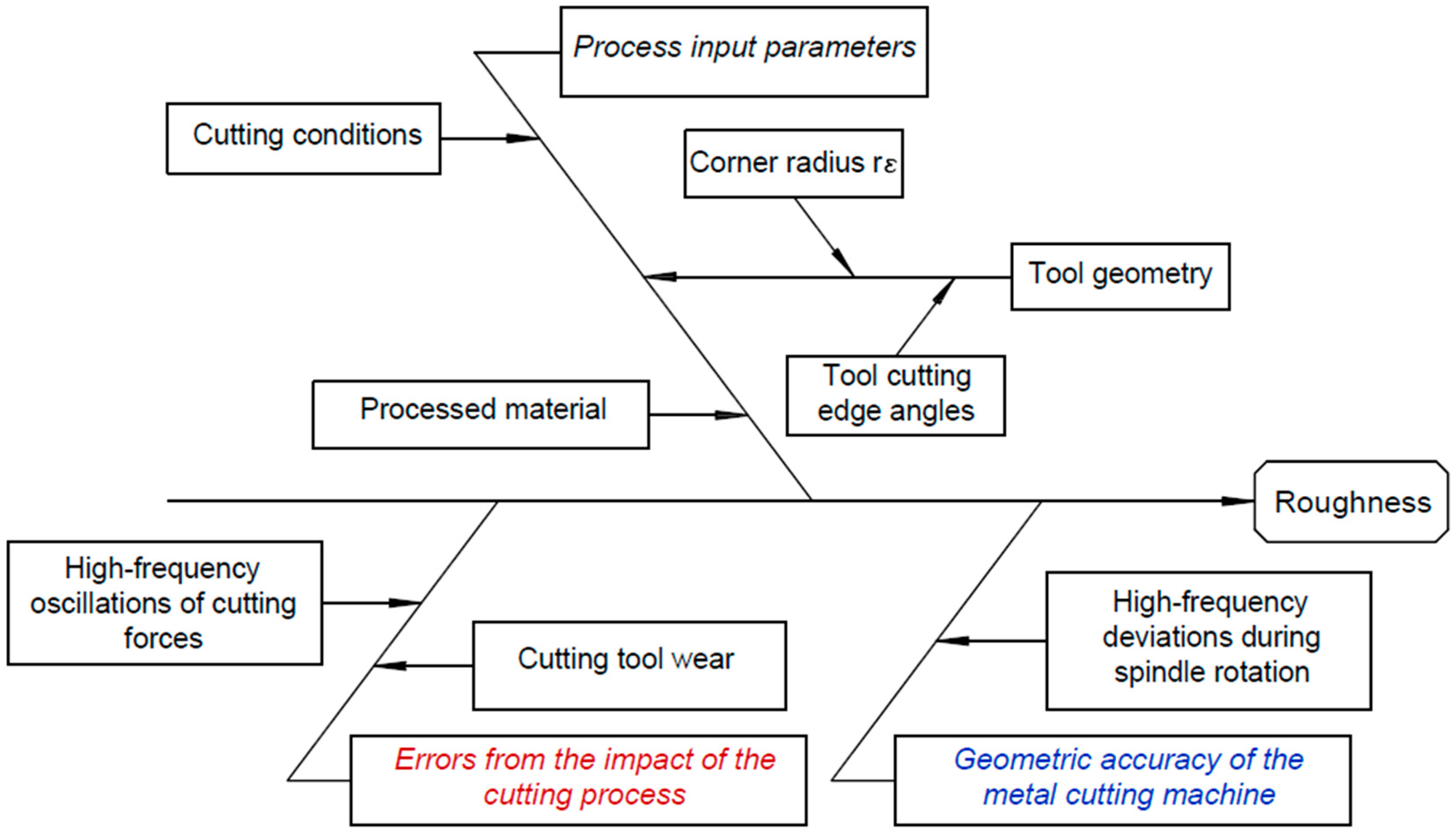
One of the most visual ways to depict the relationship between an output parameter and its influencing factors is with the help of cause-and-effect diagrams. The purpose of the performed cause-and-effect analysis is to establish the significance of the factors influencing the finishing (final) processing stage. This is related to specifying the necessary technological solutions for their provision.

2.1. Roughness

Under the conditions of finishing operations, the dominant factors determining the roughness are feed, tool nose radius, and cutting tool wear [2,4,5,6,7] (Figure 1).
If one of the other factors (material machinability, the geometric accuracy of the spindle rotation, and its oscillation from variable loads) has a more significant influence, it is compensated for by the feed. The radius at the tool tip is chosen to be as large as possible, unless there is a limitation due to internal rounding requirements or insufficient stability of the system’s Machine–Fixture–Tool–Part (MFTP). The influence of wear is limited by setting an allowable wear limit.

2.2. Cross-Sectional Shape Error

The dominant factors are the geometric accuracy of the spindle rotation and back center (Figure 2).
While the influence of the back center can be reduced by replacing it with a better-quality one, an unacceptable error due to the spindle requires the repair or replacement of the equipment. Shape errors from force factors in finishing operations occur when machining an unstable workpiece or when working with an unstable tool [8]. Technological solutions are to improve stability or introduce an intermediate transition that ensures an even allowance. In case of spotty hardness, the solution is to pre-heat treat the workpiece to reduce uneven hardness.

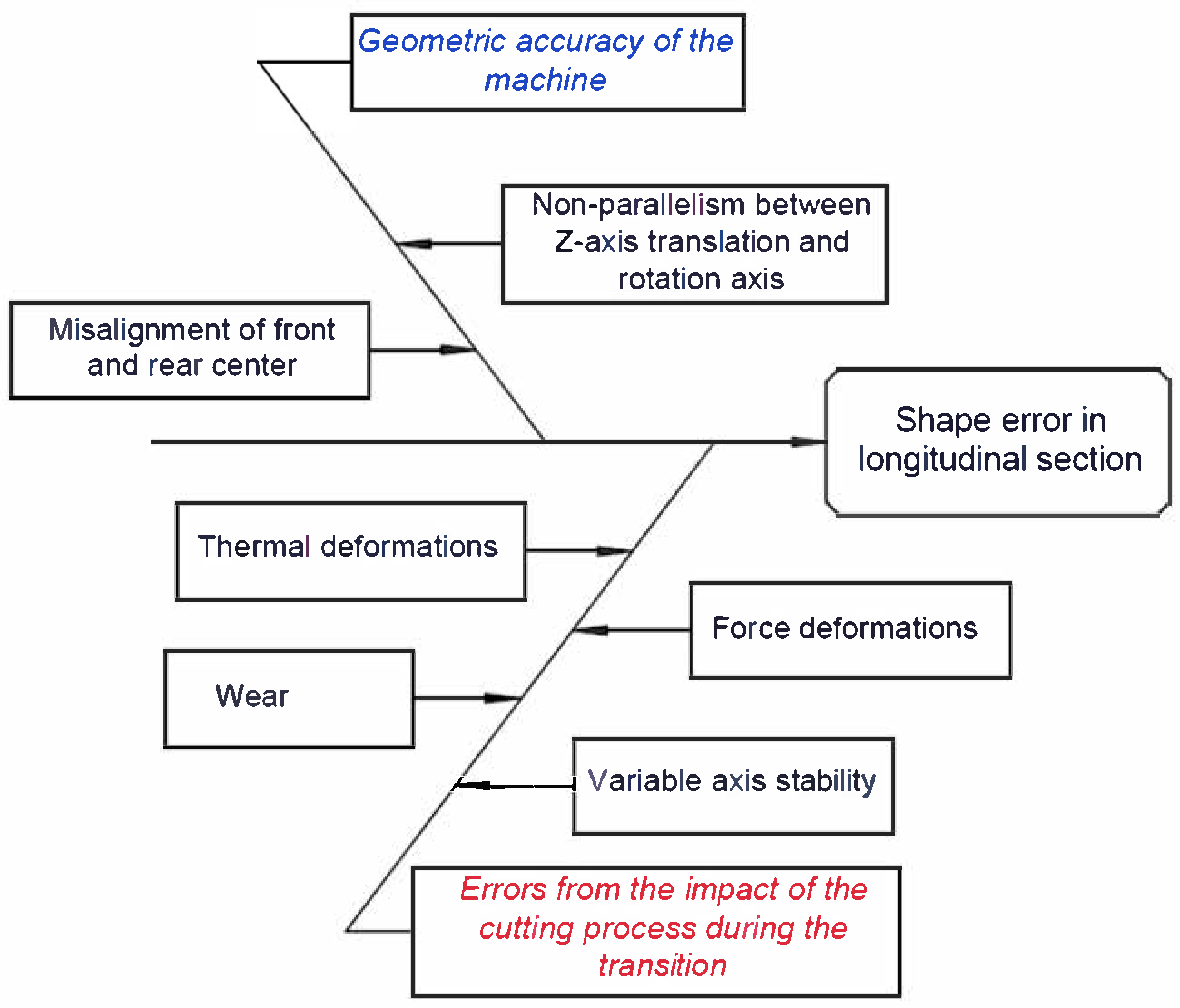
2.3. Shape Error in Longitudinal Section

Factors related to the geometric accuracy of the machine always impact the formation of this quality indicator. The shape error in the longitudinal section, caused by the accompanying phenomena of cutting (thermal, force, and wear), is influenced by insufficient stability and longer machined surfaces (Figure 3). The technological solution to reduce the latter errors is the selection of appropriate machining modes and the introduction of an additional pass if the previous machining does not guarantee an even allowance in the longitudinal section.

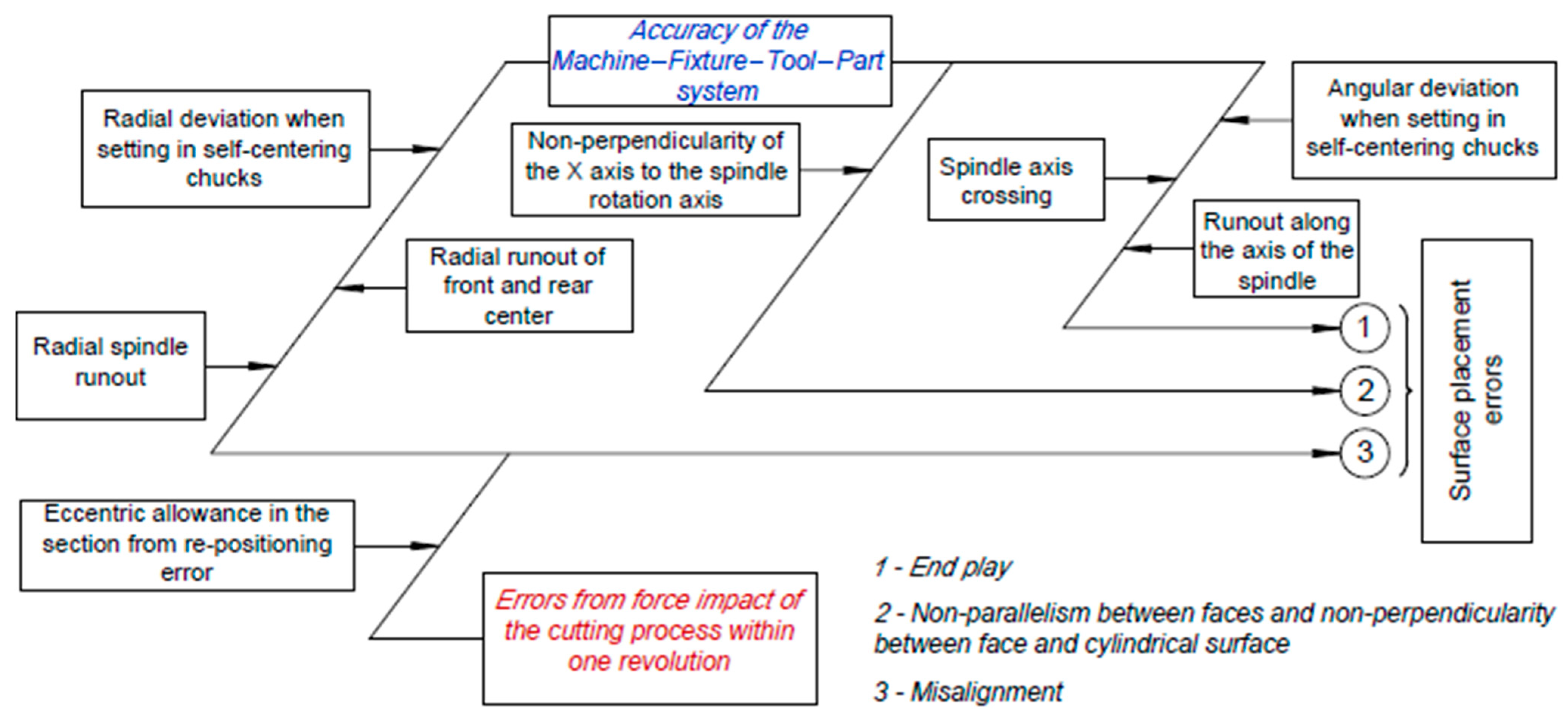
2.4. Surface Placement Error

Errors in the location of the surfaces should be considered when processing a single establishment or with a re-establishment (Figure 4).
In a setup, an error arises from force deformations as a result of processing with insufficient stability of the workpiece and the equipment for its setup. Due to the unequal stability and the different deformations along the axis of the workpiece, the machined surfaces are obtained with different displacements relative to the axis of rotation (the theoretical axis of shape- and size-forming), which also determines the misalignment between them. In finishing machining, the error in question will only occur with workpieces with very low stability. The error in the position during machining with interruption is due to the inaccuracy of the setting devices and in the position of the working elements of the machine when considering the mutual position of radial and frontal surfaces.

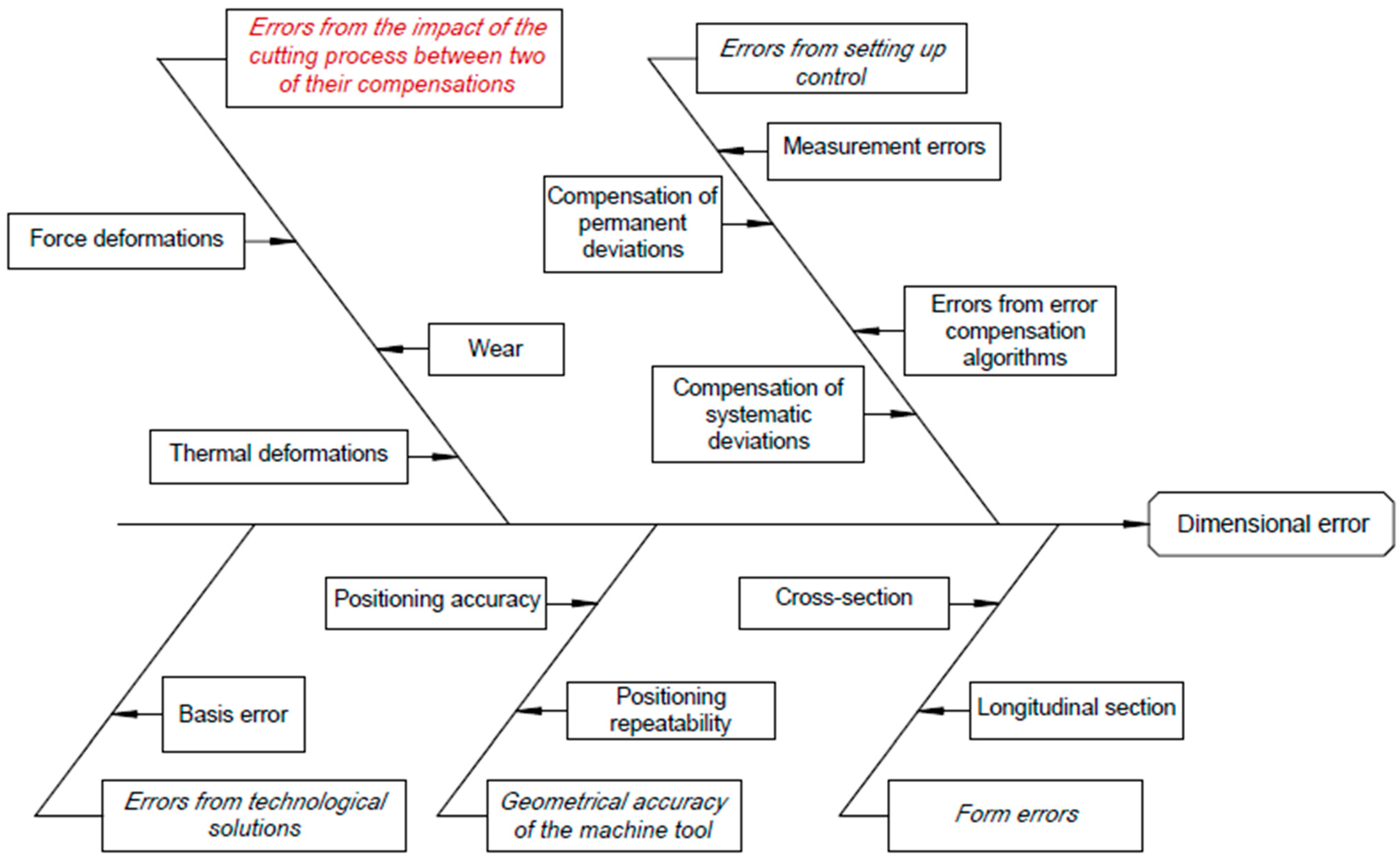
2.5. Size of the Surface

The dimensional accuracy indicator is formed under the influence of factors related to geometric accuracy; positional deviations; technological solutions determining the basing scheme; attitude control; and the effects of the cutting process (Figure 5). These factors are both systematic and random in nature [9]. The influence of many factors, some of which are a function of time, makes this indicator the most problematic to obtain.

2.6. General Regularities Related to Ensuring Accuracy

Ensuring the quality of the processed parts is a primary issue in developing efficient processes. This is because their accuracy is always a limitation in achieving economic performance. Achieving accuracy includes technical and organizational measures and activities that are embedded in or accounted for in the applied technology. In companies with an established quality management structure, some technological conditions are introduced centrally and cover all implemented technological processes. They are mainly aimed at achieving control of the workpiece parameters, familiarization and compliance with technological regulations, ambient temperature, quality cooling, taring and calibration of measuring instruments, measurement in order to determine and, if possible, compensate for deviations in the technological parameters of the processing system, etc.
The origin of errors is related to the components of the technological system (Figure 6) and can be grouped as follows: specific to the MFTP system (determined by geometric accuracy and positional deviations); caused by force, thermal load, and physical and chemical phenomena causing wear; caused by decisions made in the design of the technology—establishment schemes and the structure of the operation; caused by the thermal impact of the environment and the working environment on the MFTP system; and obtained during accuracy control (adjustment) [10]. The tasks of precision design are focused in three directions: 1. building a structure tailored to the achieved accuracy; 2. determining and ensuring the technological conditions related to achieving accuracy—a proactive measure that is implemented mainly during the design of the technology; 3. accuracy management.
Figure 7 presents the stages of technological design related to achieving accuracy.

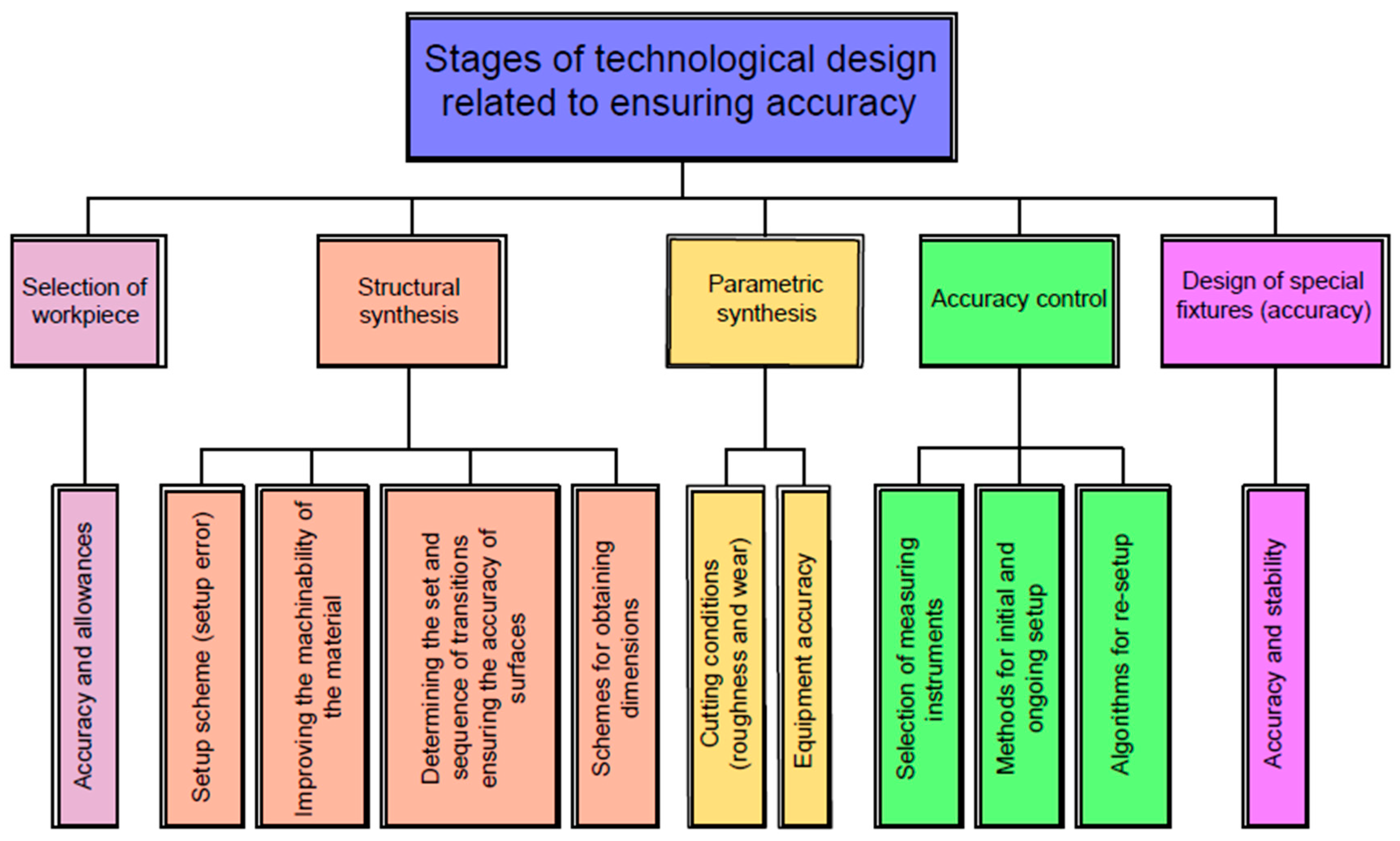
2.7. General Structural Design to Achieve Accuracy and the Formulation of Technological Conditions When Developt the Finishing Operations Accuracy

The structural design of accuracy is related to considering the impact of processing prior to finalization and building an appropriate identification and sizing scheme. In theoretical science, the following rules are justified:
  • Reliable assurance of accuracy requires that the preceding technological transition be at most two orders of magnitude less accurate;
  • The structure of the operation should ensure the execution of precise transitions when the workpiece is most stable and furthest from transitions creating high thermal loads;
  • For high accuracy, sufficient stability should be ensured L/d < 3 when the tool or workpiece is cantilevered and L/d < 10–12—when it is set between centers;
  • In the scheme of obtaining the axial dimensions, adjustment of technological bases should be used rationally [10,11];
  • Depending on the degree of uncertainty, a margin of accuracy should be set or a reserve with varying modes and more frequent fine-tuning should be provided to compensate for the part of the error exceeding its permissible value;
  • Achieving efficiency in technological design is related to applying the following principle: the adoption of each technological solution is accompanied by the question of whether there is an option in which, at the considered processing stage, the specified quality can be achieved with better values of productivity and economic indicators.
Technological conditions are part of the production conditions, determining the set of specified input parameters of the workpiece, the parameters of the processing system, and the working and environmental environment, which influence the output parameters of accuracy. Their specification is carried out during the process of designing the technology and carrying out further specification during its adaptation to the real technological conditions at the stage of its adoption. This is primarily a task of parametric design.
The formation of technological conditions is carried out using two groups of factors. The first is objectively determined by the task and production conditions (the available resources), which must be taken into account in technological design. They include the following:
  • The machinability of the material;
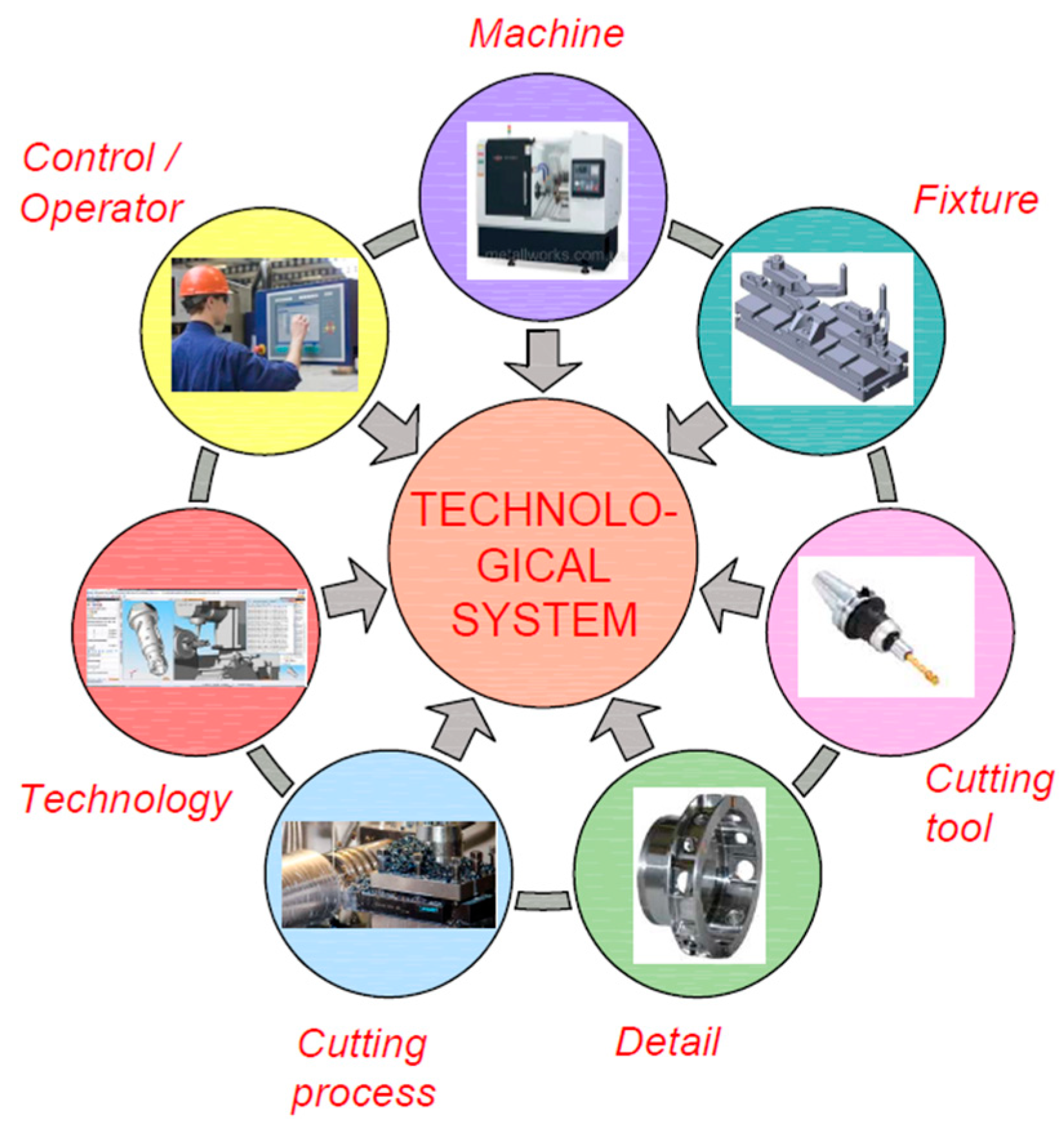
  • The current accuracy and stability of the processing system (MFTP);
  • The environment;
  • The accuracy of the measuring instruments and accuracy management tools (adjustment devices, availability of data analysis, and processing products).
The second is the result of technological solutions related to ensuring accuracy:
  • The workpiece accuracy;
  • The geometry and durability of the cutting tools;
  • The cutting conditions;
  • The accuracy and stability of the designed scheme of establishment;
  • The methodologies, regimes, and tools used for accuracy management.

3. Conclusions

  • Roughness, deviations in shape, and mutual arrangement of surfaces arise mainly from the geometric inaccuracy of the machine and the locating devices—factors that are not a function of time.
  • In the finishing stage, the group of quality parameters (from the previous point 1) does not apply, and it is not appropriate for managing accuracy. The reasons for this are as follows: factors related to phenomena (force, heat) that accompany the cutting process do not have a significant impact on finishing operations; tool wear and spindle deflection from thermal deformations affecting the shape in the longitudinal section are compensated for while ensuring the accuracy of the surface size; and the change in these parameters—random or regular—is weakly expressed. This defines this group of quality indicators as stable over time and determined by setting or selecting the parameters of the processing system at the technology design stage.
  • At the stage of finishing operations to ensure dimensional accuracy, sub-adjustment is applied to compensate for systematic factors.
  • The formation of technological conditions during the design is always subject to a number of constraints—the available means of production in the company; deadlines for fulfilling the order (time); and unprofitable costs under the conditions of fulfilling the order (economic). The influence of these constraints is mostly characteristic of wide-nomenclature production.
  • Achieving quality at maximum productivity requires processing with intensive cutting modes. Under these conditions, errors associated with processing increase, which in turn increases the required time for operational control to reliably ensure accuracy. This increase is especially significant in high-precision and concentrated machining on CNC machines, where operational control must guarantee the accuracy, not only of the final but also of the preceding transitions.

Funding

This research received no external funding.

Institutional Review Board Statement

Not applicable.

Informed Consent Statement

Not applicable.

Data Availability Statement

Data are contained within the article.

Acknowledgments

This study is supported by the project 2025–MTF–01 “Friction stir welding of high strength aluminum alloys”.

Conflicts of Interest

The author declares no conflicts of interest.

References

  1. Koleva, S.; Enchev, M. Modern Problems and Tendencies of Effective Accuracy Control of Turning Operations. AIP Conf. Proc. 2022, 2449, 060024. [Google Scholar]
  2. Koleva, S.; Velev, K. Technological Assurance of Accuracy in the Turning of Details on CNC Machines. In Proceedings of University of Ruse; Book 2.1. Mechanical Engineering and Machine-Building Technologies; University of Ruse: Ruse, Bulgaria, 2022; Volume 61, pp. 69–73. [Google Scholar]
  3. Minev, B. A priori analysis of the Bulgarian mechanical engineering sector. In Proceedings of University of Ruse; Book 5.1, Economics and Management; University of Ruse: Ruse, Bulgaria, 2012; Volume 51, ISSN 1311-3321. [Google Scholar]
  4. Kuntoğlu, M.; Aslan, A.; Sağlam, H.; Pimenov, D.Y.; Giasin, K.; Mikolajczyk, T. Optimization and Analysis of Surface Roughness, Flank Wear and 5 Different Sensorial Data via Tool Condition Monitoring System in Turning of AISI 5140. Sensors 2020, 20, 4377. [Google Scholar] [CrossRef] [PubMed]
  5. Chowdhury, T.N.; Dhar, N.R. Experimental Analysis and Modeling of Tool Wear and Surface Roughness in Hard Turning under Minimum Quantity Lubricant Environment. In Proceedings of the 2011 International Conference on Industrial Engineering and Operations Management, Kuala Lumpur, Malaysia, 22–24 January 2011. [Google Scholar]
  6. Ambhore, N.; Kamble, D.; Chinchanikar, S. Analysis of tool vibration and surface roughness with tool wear progression in hard turning: An experimental and statistical approach. J. Mech. Eng. Sci. 2020, 14, 6461–6472. [Google Scholar] [CrossRef]
  7. Das, S.R.; Panda, A.; Dhupal, D. Experimental investigation of surface roughness, flank wear, chip morphology and cost estimation during machining of hardened AISI 4340 steel with coated carbide insert. Mech. Adv. Mater. Mod. Process. 2017, 3, 9. [Google Scholar] [CrossRef]
  8. Sotirov, B.; Petrov, M.; Tonev, D. Measuring the deviation from roundness using a birefringence meter. In Proceedings of the Scientific Symposium with International Participation “Metrology and Metrological Assurance”, Sosopol, Bulgaria, 9–13 September 2010; pp. 187–192. [Google Scholar]
  9. Sotirov, B.; Tonev, D. Measurement uncertainty of simple effective diameter using measuring wires. In Proceedings of the Third National International Conference with the Participation of Metallurgy, Hydro- and Aerodynamics, National Security, Bulgarian Academy of Sciences, Sofia, Bulgaria, 24–25 October 2013; pp. 74–80, ISBN 1313-8308. [Google Scholar]
  10. Kušar, J.; Berlec, T.; Žefran, F.; Starbek, M. Reduction of Machine Setup Time. J. Mech. Eng. 2010, 56, 833–845. [Google Scholar]
  11. Georgiev, V.; Salapateva, S.; Chetrokov, I. The possibilities of increasing the accuracy of active inspection of CNC lathes using adaptive accuracy control. In Proceedings of the AMTECH 2005, Ruse, Bulgaria, 10–12 November 2005; pp. 386–391. [Google Scholar]
Figure 1. Cause-and-effect diagram for ensuring roughness.
Engproc 100 00014 g001
Figure 2. Cause-and-effect diagram for cross-sectional error formation.
Engproc 100 00014 g002
Figure 3. Cause-and-effect diagram for the formation of an error in a longitudinal section.
Engproc 100 00014 g003
Figure 4. Cause-and-effect diagram for the formation of an error in the placement of surfaces.
Engproc 100 00014 g004
Figure 5. Cause-and-effect diagram for the formation of the size error.
Engproc 100 00014 g005
Figure 6. Components of the technological system.
Engproc 100 00014 g006
Figure 7. Stages of technological design related to achieving accuracy.
Engproc 100 00014 g007
Disclaimer/Publisher’s Note: The statements, opinions and data contained in all publications are solely those of the individual author(s) and contributor(s) and not of MDPI and/or the editor(s). MDPI and/or the editor(s) disclaim responsibility for any injury to people or property resulting from any ideas, methods, instructions or products referred to in the content.

