Abstract
Electric vehicle applications frequently use brushless direct-current (BLDC) motors due to their high torque and efficiency. However, coil damage may result from their use at high rotating speeds and extremely high temperatures, requiring preventative maintenance. This study describes the creation of a better online monitoring platform that is coupled with an improved fault detection and protection system for small electric vehicles. Designing a fault detection system with real-time analysis to identify open-circuit problems is part of the process. The results indicate that the reliability and operating efficiency of electric vehicle applications have been greatly enhanced by the development of a potential fault-monitoring and protection solution.
1. Introduction
Brushless direct-current (BLDC) motors have become a critical component in various industries, particularly in electric vehicle applications, due to their high torque, efficiency, and reliability. However, frequent use of these motors at high speeds and in difficult conditions, including high temperatures, might lead to wear and tear, especially in the coils. If not handled promptly, this could lead to serious problems such open-phase faults, phase imbalances, and other electrical anomalies which could potentially result in expensive system failures and operational downtimes [1,2,3]. Conventional motor fault detection methods usually depend on offline diagnostics or recurring inspections, which are frequently insufficient to identify early indications of deterioration. There is a pressing demand for more proactive and reliable fault detection methods because these reactive approaches are unable to stop defects from becoming serious problems [4,5,6].
Regarding these limitations, this study proposes the development of a real-time monitoring platform that is specifically designed for BLDC motors. This platform integrates modern sensor technology and real-time signal processing algorithms to continuously monitor key electrical parameters such as current and voltage signals [7,8,9,10]. The platform is capable of detecting deviations from normal operating conditions, enabling the early detection of faults such as open-phase conditions and torque ripples [11,12,13]. The goal is to provide operators with real-time alerts, allowing for immediate corrective actions to prevent further damage and minimize downtime [14,15,16]. The proposed platform is evaluated through experimental tests, and the results demonstrate its effectiveness in detecting and classifying various fault conditions in real time. These findings are further discussed and compared with the motor’s performance in normal operational and fault-induced states, highlighting the platform’s utility in industrial applications.
This research presents a novel real-time fault management platform for monitoring drives, addressing the critical vulnerability of power semiconductor devices to open-circuit faults and their cascading consequences. Departing from computationally intensive analytical approaches that often rely on AI or complex signal processing yet lack immediate protection and visualization, this platform integrates real-time current and voltage monitoring, rapid open-circuit fault detection, and immediate protective measures to mitigate damage to the drive system, including the control unit, Hall sensors, and motor windings. This integrated approach, combining real-time monitoring, protection, and online visualization, offers a practical and readily deployable solution, bridging the gap between complex offline analysis and the imperative for immediate fault response, ultimately enhancing system reliability and reducing maintenance costs. Experimental results will validate the platform’s efficacy in mitigating damage under various operating conditions.
2. Proposed Real-Time Monitoring Platform
Mathematic Model
This Section presents the mathematical model, as shown in the following equations.
where Te is the electromagnetic torque of the motor, ωm is the rotor’s angular velocity, Va, Vb and Vc are the voltages of phases a, b, and c. ia, ib and ic are the currents phases a, b and c [17].
The increasing use of motors in critical applications demands the development of advanced systems for real-time fault detection and motor health monitoring. Traditional monitoring techniques, which often rely on periodic inspections and offline diagnostics, are insufficient for detecting early signs of degradation, leading to costly downtimes and potential system failures. To address these limitations, we propose a real-time monitoring platform that is designed specifically for motors, and is capable of detecting various fault conditions such as open-phase faults, phase imbalances, and other electrical anomalies. The proposed platform integrates modern sensor technology with high-speed data acquisition systems to continuously monitor key electrical parameters, including current and voltage signals. By employing real-time signal processing algorithms, the system can analyze the motor’s behavior and identify deviations from normal operating conditions. This enables the detection of faults at an early stage, allowing operators to take preventive action before a minor issue escalates into a critical failure [18].
3. Materials and Methods
This Section describes the methodology employed in this study, which integrates a real-time fault detection system for motors, utilizing a combination of voltage comparators and low-pass filters to ensure the reliable detection of electrical faults, such as open-phase and phase imbalance conditions. This approach emphasizes the continuous monitoring of motor health through high-speed data acquisition and signal processing, enabling fault detection before significant system failures occur.
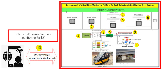
Figure 1 depicts the architecture of a real-time monitoring and fault detection platform designed to enhance the reliability of motor drive systems, particularly within electric vehicles (EVs). For thorough defect detection and system monitoring, the platform combines hardware and software components. The following are the main modules.

Figure 1.
Real-time monitoring and fault detection platform.
- (1)
- Motor Control Module: This module is in charge of producing the pulse-width modulation (PWM) signals that power the inverter and serves as a representation of the current motor control system.
- (2)
- Motor Status Module: This module keeps track of the BLDC motor’s speed, torque, and temperature in real time, giving predictive maintenance and fault analysis context.
- (3)
- Inverter Control Module: This module controls the inverter transistors’ switching in response to PWM signals. Because abnormalities frequently show up in output currents or switching behavior, it is essential for fault identification.
- (4)
- Battery Module: This module serves as the power source, and it is crucial for system dependability, particularly in EVs, to monitor the state of health (SOH) and state of charge (SOC).
- (5)
- Protection Module: This module prevents more harm by implementing protective actions, such as torque reduction or system shutdown, upon fault detection.
- (6)
- Fault Detection Board: The circuitry for signal acquisition, processing, and communication is housed in this hardware component. It includes a microcontroller for fault detection algorithms as well as current and voltage sensors.
- (7)
- Monitoring modules for overvoltage, under voltage, and transient voltage are essential for protection components and monitoring safety operation.
- (8)
- Overcurrent monitoring modules: These are crucial for avoiding damage to the inverter and windings.
- (9)
- Open-phase fault test: This feature allows fault detection and protection algorithms to be tested and validated by experimental open-phase faults.
- (10)
- Internet-based platform condition monitoring and online preventive maintenance. By integrating the platform with an internet-based monitoring system, these components allow for remote diagnostics and predictive maintenance.
3.1. System Design and Data Acquisition
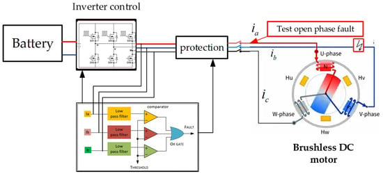
The proposed fault detection system is designed to monitor three primary current signals, Ia, Ib and Ic, which represent the three phases of the motor. Each of these current signals is passed through a low-pass filter to remove high-frequency noise and transients. This ensures that only the essential fault-related signals are processed, eliminating the risk of false detections caused by transient spikes or switching harmonics from the inverter. The use of low-pass filters ensures that any deviations in the current signals are accurately captured without interference from unwanted noise. Next, the filtered signals are compared against a predefined threshold using voltage comparators. The comparators are configured to switch to a fault state when any of the filtered current signals drop below or exceed the predefined threshold, indicating a fault in one of the motor phases. If a fault is detected, the comparator output is sent to an OR gate that consolidates the results from all three comparators. This gate triggers a unified fault signal if any one of the phases experiences a deviation, enabling real-time response and corrective actions.
3.2. Fault Detection Mechanism
The primary goal of the system is to detect two types of faults: open-phase conditions and phase imbalances. These faults can severely affect motor performance and efficiency, causing phenomena such as torque ripples, increased harmonics, and potential overheating.
- Open-Phase Fault Detection: When an open-phase fault occurs, the current in the affected phase drops to zero, causing an imbalance in the motor’s operation. The voltage comparator detects this deviation, and the OR gate signals a fault, allowing operators to take immediate action to mitigate further damage.
- Phase Imbalance Detection: In the case of phase imbalances, where one or more phases deviate from the normal current range but do not drop to zero, the system detects the inconsistency and signals a fault. This early detection prevents long-term damage to the motor by enabling timely intervention.
3.3. Real-Time Monitoring Platform
The proposed real-time monitoring platform integrates several components to facilitate continuous motor health monitoring. Sensor inputs capture the current and voltage signals from the motor phases, which are then processed by the low-pass filters and voltage comparators to detect any deviations from normal operation. The processed data is visualized through a user interface, providing real-time feedback to operators and allowing for the quick identification of faults. The platform also includes an alert system that sends notifications to the operator or control system when a fault is detected. This ensures that faults are addressed promptly, preventing catastrophic motor failures. Additionally, the system stores data for further analysis, enabling the detailed examination of motor performance trends and potential fault patterns.
3.4. Experimental Setup and Testing
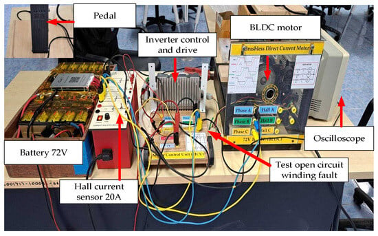
To validate the effectiveness of the proposed system, the methodology was tested under both normal and fault conditions as shown in Figure 2. The experimental setup included a 72 V 40 Ah lithium NMC battery, current sensor 20 A, and inverter drive control 50 A. Initially, the motor was operated at 1500 RPM under no-load conditions and the current and voltage waveforms were recorded. These waveforms exhibited stable and balanced profiles with minimal ripples, indicating normal operation.

Figure 2.
Test setup for demonstrating BLDC motor fault.
Next, the system was tested under fault conditions, including open-circuit and phase imbalance faults. During open-circuit testing, the current signal for the faulty phase dropped to zero, and the system successfully triggered the fault signal through the OR gate, as shown in Figure 3. Phase imbalances were also detected, with the current waveform showing increased harmonic content and distortions. In both cases, the system’s response time was fast, providing immediate feedback and enabling preventive measures.

Figure 3.
Current and voltage waveforms of the BLDC motor in a normal state.
The methodology outlined in this study demonstrates a robust fault detection system for motors, combining low-pass filters and voltage comparators to detect open-phase faults. This approach provides a cost-effective and scalable solution that is suitable for various industrial applications where motors are critical.
The EV motor product from Thailand’s parameter values used in this investigation are shown in Table 1. The parameter values of the central processing unit and the signal detection apparatus, such as the vibration, voltage, and current sensors, are shown in Table 2.

Table 1.
BLDC motor parameters.

Table 2.
Detection device.
4. Results and Discussions
This Section presents the experimental results on fault detection and the analysis of current and voltage signals during fault conditions.
The current and voltage waveforms of the motor at 1500 RPM exhibit characteristics that are typical of normal operation. The voltage and current waveform maintains a smooth and balanced profile, reflecting a stable three-phase power supply, while the current waveform shows minor ripples, attributable to expected inverter commutation and switching harmonics. The open-phase of significant distortion, asymmetry, or irregularities suggests that there are no winding faults, load imbalances, or supply issues present. These observations indicate that the motor is functioning in a stable condition, with no immediate signs of potential faults or degradation.
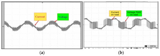
Figure 4 shows current and voltage signals during normal operation (a) and under load operation (b) when the motor operates with a load of 0.5 Nm at the same speed of 1500 RPM. The current signal exhibits a more distorted sinusoidal waveform, with an approximate 20% increase in current magnitude and harmonic content compared to no-load operation. This distortion and increased harmonic content result directly from the motor driving the load, which increases current demand and leads to higher inverter output switching activity.

Figure 4.
Current and voltage waveform in load-driving condition.
4.1. Open-Circuit Fault Condition
In electric vehicle systems, prolonged use can lead to malfunctions within the drive system, such as a damaged Insulated Gate Bipolar Transistor (IGBT) module. This failure can result in incomplete circuit connections between the motor phases, leading to issues such as short circuits between the phases or the absence of one phase in the motor windings. Such faults are critically dangerous, posing severe risks to both equipment and human safety. To address this, the current study simulates an open-circuit fault condition in a BLDC motor. The experimental results, shown in Figure 5a, indicate that during an open-circuit fault, the current signal drops to zero when the drive system fails.

Figure 5.
Current signal under open-circuit fault.
Figure 5b displays an open-phase fault in a motor, where one phase is no longer conducting properly. This results in the significant distortion of the current waveform, as evidenced by the erratic fluctuations in the fault current signal. The interruption of one phase causes imbalances in the motor operation, leading to increased harmonics and unitability in the current signal. This fault condition induces torque ripples, which can cause mechanical vibrations and reduce motor efficiency. The irregular current flow and related torque ripple could lead to overheating and potential motor damage if not addressed promptly. The waveform provides a clear visual representation of how an open-phase fault disrupts motor performance, emphasizing the importance of early detection and repair to prevent further system damage.
4.2. Discussions
The results demonstrate that the proposed real-time monitoring platform enhances motor reliability by enabling continuous fault detection and diagnosis. By promptly identifying open-phase and phase imbalance faults, the system reduces the risk of prolonged motor damage and minimizes operational downtime. Unlike traditional fault detection methods, which rely on large datasets and offline diagnostics, the proposed platform provides a proactive and efficient solution with minimal hardware requirements. These attributes make the platform a practical and scalable choice for industrial and automotive applications.
5. Conclusions
This paper presents the development of a real-time monitoring platform that is designed to detect and diagnose faults in motors, particularly for electric vehicle applications. By continuously monitoring current and voltage waveforms, the system effectively identifies early signs of motor degradation, including open-circuit faults, phase imbalances, and torque ripples. Experimental results confirm that the proposed platform enhances fault detection compared to conventional methods, enabling timely corrective actions that minimize motor damage and reduce downtime. In contrast to traditional fault detection techniques, such as offline diagnostics and periodic inspections, the proposed real-time platform offers significant advantages. Conventional methods typically require large datasets and extensive tuning, which are time-consuming and susceptible to overfitting. The proposed platform provides a simpler and more robust solution for fault detection and protection without the need for extensive training data [19,20,21].
Author Contributions
S.M.: conceptualization, methodology, software, formal analysis, investigation, writing—original draft; N.P.: conceptualization, methodology, software, investigation, supervision, writing—review and editing.; S.P.: writing—review and editing, supervision. All authors have read and agreed to the published version of the manuscript.
Funding
This research was funded by Fundamental Fund year 2024 and Nakhon Phanom University, Thailand.
Data Availability Statement
The data are available from the authors upon appropriate request.
Conflicts of Interest
The authors declare no conflicts of interest.
References
- Kim, T.H.; Lee, H.W.; Kwak, S.S. The internal fault analysis of brushless DC motors based on the winding function theory. IEEE Trans. Magn. 2009, 45, 2090–2096. [Google Scholar]
- Arkan, M.; Perovic, D.L.; Unswoth, P. On-line stator winding fault diagnosis in induction motors. Proc. Inst. Elect. Eng.—Elect. Power Appl. 2001, 148, 537–547. [Google Scholar] [CrossRef]
- Cheng, S.; Zhang, P.; Habetler, T.G. An impedance identification approach to sensitive detection and location of stator turn-to-turn faults in a closed-loop multiple-motor drive. IEEE Trans. Ind. Electron. 2011, 58, 1545–1554. [Google Scholar] [CrossRef]
- Lee, Y.; Habetler, T. An on-line stator turn fault detection method for interior PM synchronous motor drives. In Proceedings of the 22nd Annual IEEE Conference on Applied Power Electronics Conference, Anaheim, CA, USA, 25 February–1 March 2007; pp. 825–831. [Google Scholar]
- Kim, K.T.; Park, J.K.; Hur, J.; Kim, B.W. Comparison of the fault characteristics of IPM-type and SPM-type BLDC motors under inter-turn fault conditions using winding function theory. IEEE Trans. Ind. Appl. 2014, 50, 986–994. [Google Scholar] [CrossRef]
- Lu, B.; Sharma, S. A literature review of IGBT fault diagnostic and protection methods for power inverters. IEEE Trans. Ind. Appl. 2009, 45, 1770–1777. [Google Scholar]
- Nejad, M.S.; Mobarakeh, B.N.; Pierfederici, S.; Tabar, F.M. Fault tolerant and minimum loss control of double-star synchronous machines under open phase conditions. IEEE Trans. Ind. Electron. 2008, 55, 1015–1020. [Google Scholar]
- Rothenhagen, K.; Fuchs, F.W. Performance of diagnosis methods for IGBT open circuit faults in voltage source active rectifiers. In Proceedings of the 2004 IEEE 35th Annual Power Electronics Specialists Conference, Aachen, Germany, 20–25 June 2004; pp. 4348–4354. [Google Scholar]
- Sleszynski, W.; Nieznanski, J.; Cichowski, A. Open-transistor fault diagnostics in voltage-source inverters by analyzing the load currents. IEEE Trans. Ind. Electron. 2009, 56, 4681–4688. [Google Scholar] [CrossRef]
- Ribeiro, R.L.A.; Jacobina, C.B.; da Silva, E.R.C.; Lima, A.M.N. Fault detection of open-switch damage in voltage-fed PWM motor drive systems. IEEE Trans. Power Electron. 2003, 18, 587–593. [Google Scholar] [CrossRef]
- Awadallah, M.A.; Morcos, M. Automatic diagnosis and location of openswitch fault in brushless dc motor drives using wavelets and neuro-fuzzy systems. IEEE Trans. Energy Convers. 2006, 21, 104–111. [Google Scholar] [CrossRef]
- Khomfoi, S.; Tolbert, L.M. Fault diagnosis and reconfiguration for multilevel inverter drive using AI-based techniques. IEEE Trans. Ind. Electron. 2007, 54, 2954–2968. [Google Scholar] [CrossRef]
- Joksimovic, G.M.; Penman, J. The detection of inter-turn short circuits in the stator windings of operating motors. IEEE Trans. Ind. Electron. 2000, 47, 1078–1084. [Google Scholar] [CrossRef]
- Kallese, C.S.; Zamanabadi, R.I.; Vadstrup, P.; Rasmussen, H. Observer-based estimation of stator-winding faults in delta-connected induction motors: A linear matrix inequality approach. IEEE Trans. Ind. Appl. 2009, 43, 1022–1032. [Google Scholar] [CrossRef]
- Lee, B.-K.; Kim, T.-H.; Ehasani, M. On the feasibility of four-switch three-phase BLDC motor drives for low cost commercial applications: Topology and control. IEEE Trans. Power Electron. 2003, 18, 164–172. [Google Scholar]
- Skóra, M.; Kowalski, C.T. Influence of sensor faults on PM BLDC drive. Zesz. Probl.—Masz. Elektr. 2014, 104, 37–42. (In Polish) [Google Scholar]
- Huang, Q.; Luo, L.; Zhang, X.; Diao, L. Fault tolerant control for open winding brushless DC motor with power device failure. J. Electr. Eng. Technol. 2024, 19, 3175–3189. [Google Scholar] [CrossRef]
- Tashakori, A.; Ektesabi, M. A simple fault tolerant control system for Hall effect sensors failure of BLDC motor. In Proceedings of the IEEE Industrial Electronics and Applications (ICIEA’13), Melbourne, Australia, 19–21 June 2013; pp. 1011–1016. [Google Scholar]
- Dong, L.; Jatskevich, J.; Huang, Y.; Chapariha, M.; Liu, J. Fault diagnosis and signal reconstruction of Hall sensors in brushless permanent magnet motor drives. IEEE Trans. Energy Convers. 2015, 31, 118–131. [Google Scholar] [CrossRef]
- Scelba, G.; De Donato, G.; Scarcella, G.; Capponi, F.G.; Bonaccorso, F. Fault-tolerant rotor position and velocity estimation using binary Hall-effect sensors for low-cost vector control drives. IEEE Trans. Ind. Appl. 2014, 50, 1629–1636. [Google Scholar] [CrossRef]
- Buja, G.; Bertoluzzo, M.; Keshri, R.K. Torque ripple-free operation of PM BLDC drives with petal-wave current supply. IEEE Trans. Ind. Electron. 2015, 62, 4034–4043. [Google Scholar] [CrossRef]
Disclaimer/Publisher’s Note: The statements, opinions and data contained in all publications are solely those of the individual author(s) and contributor(s) and not of MDPI and/or the editor(s). MDPI and/or the editor(s) disclaim responsibility for any injury to people or property resulting from any ideas, methods, instructions or products referred to in the content. |
© 2025 by the authors. Licensee MDPI, Basel, Switzerland. This article is an open access article distributed under the terms and conditions of the Creative Commons Attribution (CC BY) license (https://creativecommons.org/licenses/by/4.0/).