Abstract
This study presents a simulation modeling of the gravity filling of a sand casting mold with gray cast iron EN-GJL-250. An analysis of the fluid flow, the nature of the filling of the casting mold, and the possibility of forming defects, such as voids and porosity due to metal shrinkage during the crystallization process, was performed. The simulation was performed using specialized software for simulating metal casting processes. The software allows the modeling of fluid dynamics and thermal conditions during the filling of the casting mold. The results obtained show the influence of the design of the sprue system, pouring temperature, and casting geometry on the movement of the fluid flow and the crystallization of the metal. The simulation also allows the visualization of turbulence and temperature gradients, helping to localize areas prone to defects. The results of this study could improve the quality of the specific casting and aid in selecting appropriate technology for the casting of a small series of high-quality castings.
1. Introduction
The introduction of computer software into the world of foundry practice has become an integral part of scientific research, design, and development activities related to the refinement and optimization of foundry technologies, the creation of castings with high performance qualities, reducing metal consumption, achieving energy savings, sharply reducing the time taken by the design–implementation cycle, and fast and accurate qualitative and quantitative diagnostics for a wide range of possible defects. In modern industry, the simulation of foundry processes is a widespread and generally recognized tool for improving the yield and quality of castings. As a result of continuous development and close contact with the industry and the experience of leading metallurgists, specialized foundry software was developed based on the proven Finite Element technology. The software provides complete solutions for a wide range of casting processes and for casting any metal alloy, covering the full spectrum of industrial needs and casting processes. The program allows the simulation of the filling of the mold, the crystallization of the alloy, and its microstructure. The location and shape of the dead heads, coolers, and exothermic sleeves and their influence on the shrinkage/suction can be viewed and analyzed directly on the monitor to achieve a tool and process that guarantees high quality [1,2,3]. The precise geometry created by “finite elements” provides an opportunity to simulate the metal level inside the mold, accurately predicting core erosion and turbulence, trapped air, underfill and non-bonding, and the fluid front and position. The fluid level can be analyzed in conjunction with thermal and strength analysis, and the fluid solver can be assigned specific models for turbulence analysis [4,5,6,7,8]. The thermal solver allows the simulation of heat flows during casting, considering thermal conductivity, convection, and radiation. Changes in heat balance, phase transformations during crystallization, and phase transformations in the solid state are described by enthalpy. Results are obtained from thermal solver visualization and data for thermal nodes, macro and micro porosity, mold cooling, and thermal optimization. The strength solver, working in conjunction with the thermal or fluid solver, provides answers for thermal and mechanical contact, residual stress, cracks and deformations, hot cracks and destruction, and stress concentration in the casting and mold [9,10,11,12].
2. Materials and Methods
To simulate the process of casting and crystallization in a sand casting mold with EN-GJL-250, we used the ProCast 2018.0 software product [12]. The proposed GJL 250 is a gray cast iron that contains graphite in the form of flakes (also known as Flake Graphite Iron). Gray iron has good compressive strength and offers good damping characteristics. In common with all gray iron grades, EN-GJL-250 is readily machinable and has excellent casting properties. The graphite offers lubricating properties, which have advantages in sliding wear applications. The normal chemical composition should be C = 2.8–3.3, Si = 1.2–1.7, Mn = 0.8–1.2, P ≤ 0.15, S ≤ 0.12 [13,14,15,16]. The properties of cast iron depend largely on the morphology, amount, and anisotropy of the graphite phase. It is used for housings where the stiffness of the component is more important than its tensile strength, such as internal combustion engine cylinder blocks, pump housings, valve bodies, electrical boxes, and decorative castings. Gray cast iron’s high thermal conductivity and specific heat capacity are often exploited to make cast iron cookware and disk brake rotors [17,18].
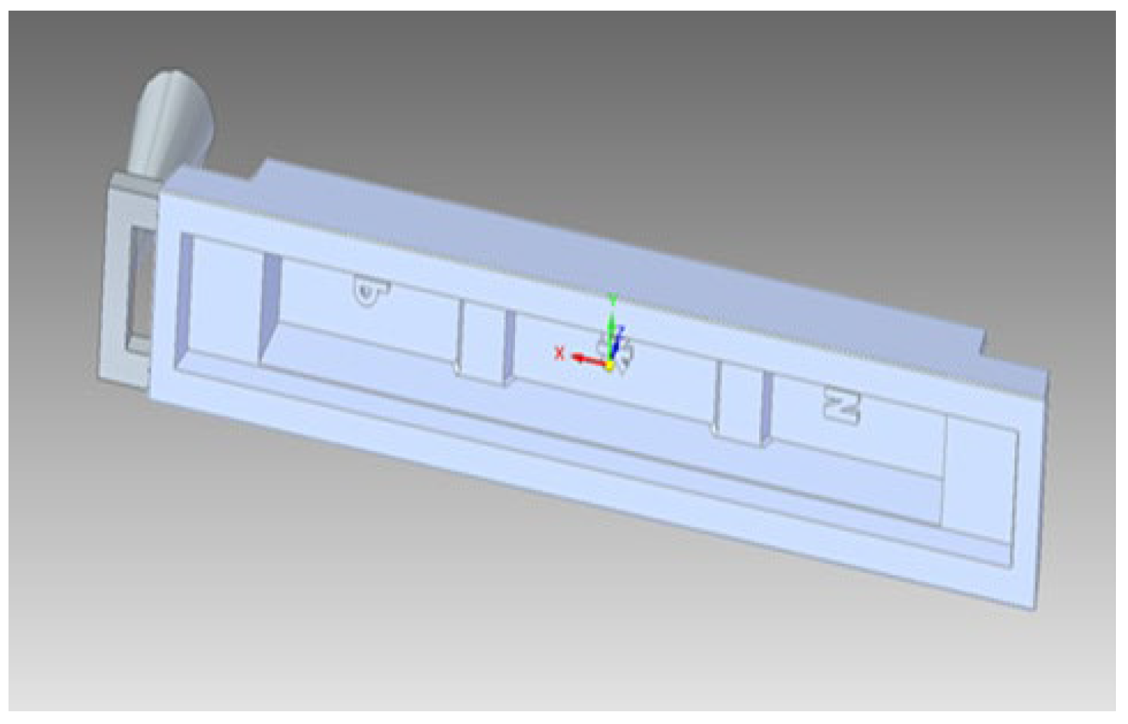
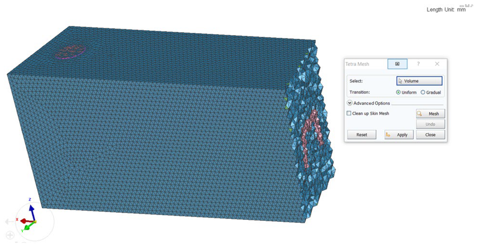
The 3D model of the “Body” part created in the Solid Works environment (Figure 1) must first be saved in a suitable format for work in the ProCAST environment (IGS). This is carried out so that the Mesh auxiliary software (mesh opening, hole, cell, closed loop) can read the surface of the object. After opening the file, if necessary, a “correction” of the geometry of the object is made. The CHECK GEOMETRY button checks the quality of the file geometry and identifies gaps in the model that can be eliminated. After fixing the geometry errors, the model is meshed (Figure 2). To reduce the calculation time, we have set the mesh size to 5 mm for the casting and 10 mm for the sand mold. After the meshing, the mesh is checked and calculated. In this case, two components are clearly distinguished—the mold and casting, which allows us to define different boundary conditions and assign different materials.

Figure 1.
Three-dimensional model of the casting with the gating system.
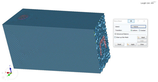
Figure 2.
Calculating the 3D mesh.
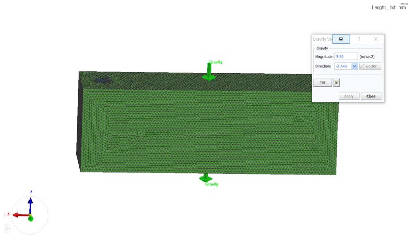
When the 3D mesh is achieved, we open the ‘Cast’ module and set the gravity pouring direction. In this case, we set the -Z Axis direction (Figure 3).

Figure 3.
Opening the “Cast” module.
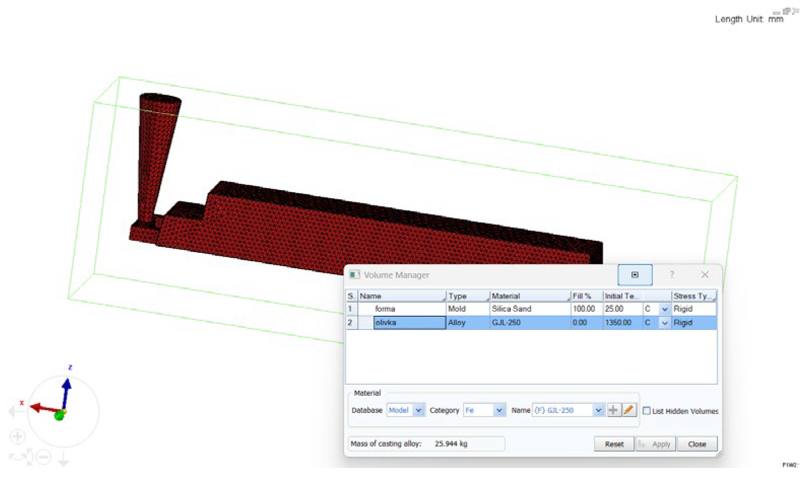
After that, we select materials for the casting and mold and set their temperature (Figure 4).
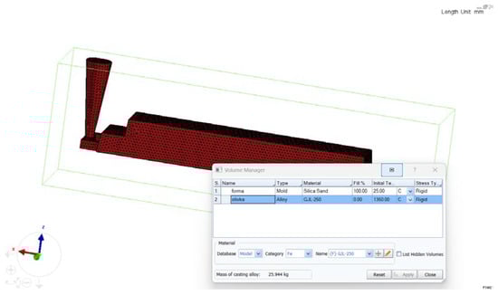
Figure 4.
Material selection and temperature setting.
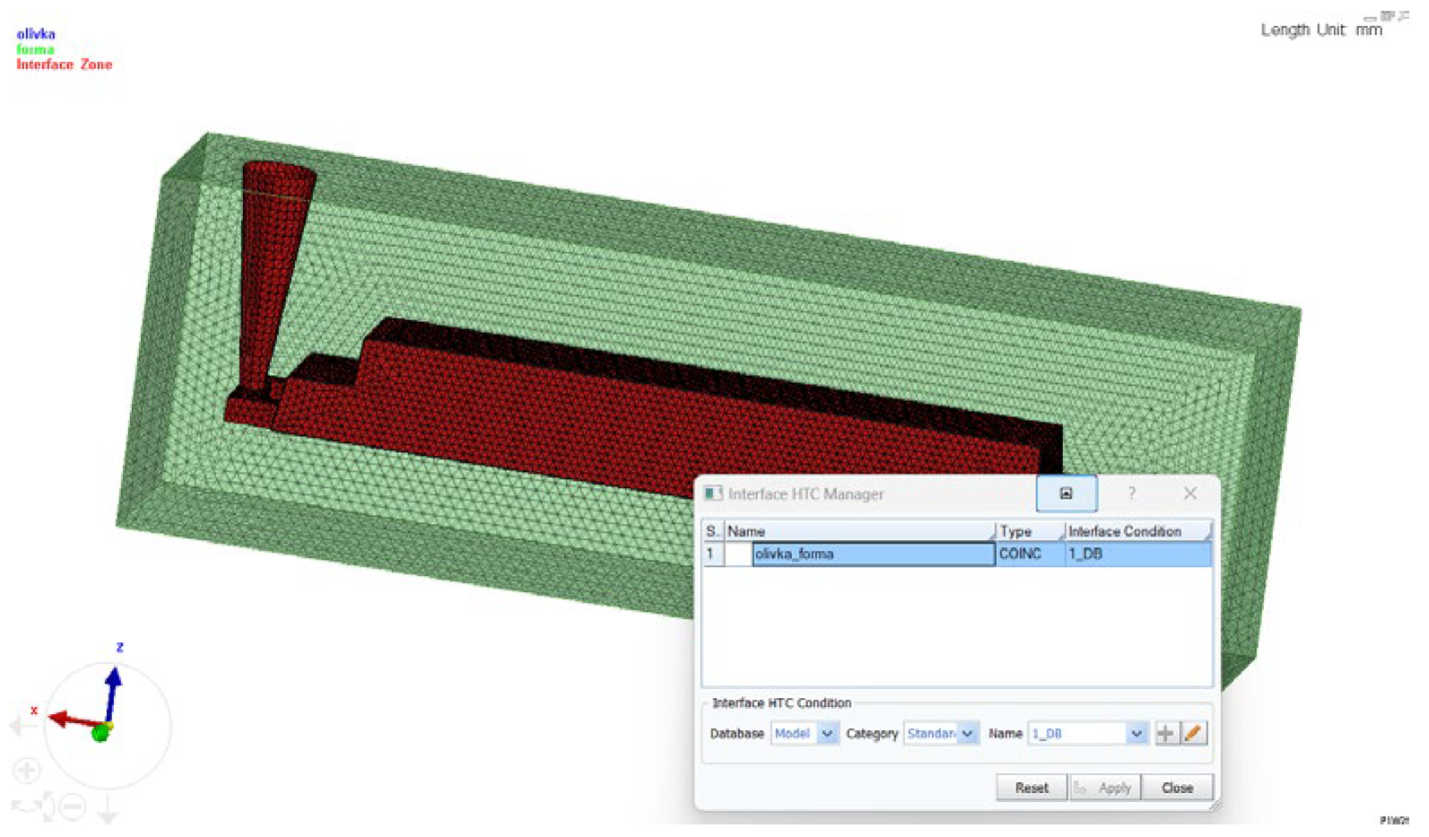
For the casting, gray cast iron EN-GJL-250 was chosen, with an alloy temperature of 1350 °C. For the mold, silica sand was selected, and the mold temperature was set to 25 °C (Figure 4). The next step was setting the thermal conductivity coefficient. With the software, it is possible to directly feed thermal conductivity (Figure 5).

Figure 5.
Setting the thermal conductivity coefficient.
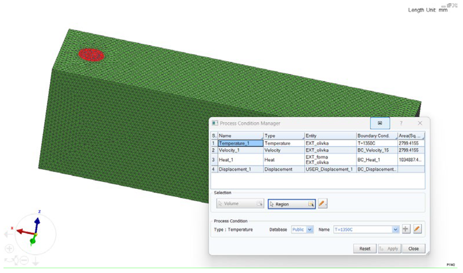
After that, the pouring temperature, the gating area through which the metal enters the mold, the pouring rate, and the type of cooling were set (Figure 6).
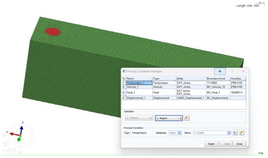
Figure 6.
Setting the pour temperature.
In the end, the method of filling the mold was set, and the calculation step and the stopping temperature were entered. The pouring method was “Gravity Filling”, the TSTOP final temperature was 11.23 °C, and the NSTEP step was 200,000.
3. Results
After starting the simulation, the ‘Visual Viewer’ module opens, where the filling process can be observed at any moment during the simulation (Figure 7 and Figure 8).
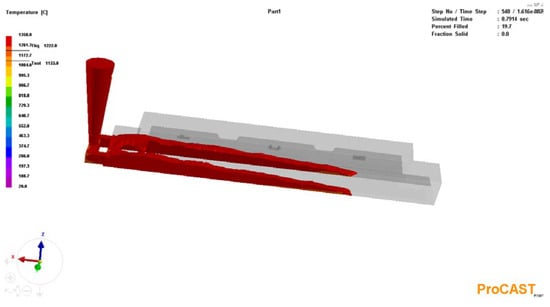
Figure 7.
Start of pouring.
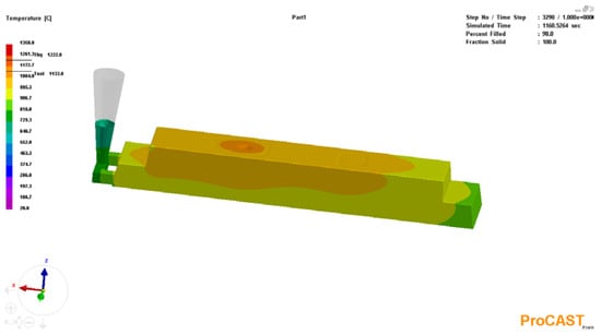
Figure 8.
Complete filling of the casting mold—100% metal crystallization.
Fluid flow visualization allows us to observe areas of turbulent or laminar metal behavior in the mold.
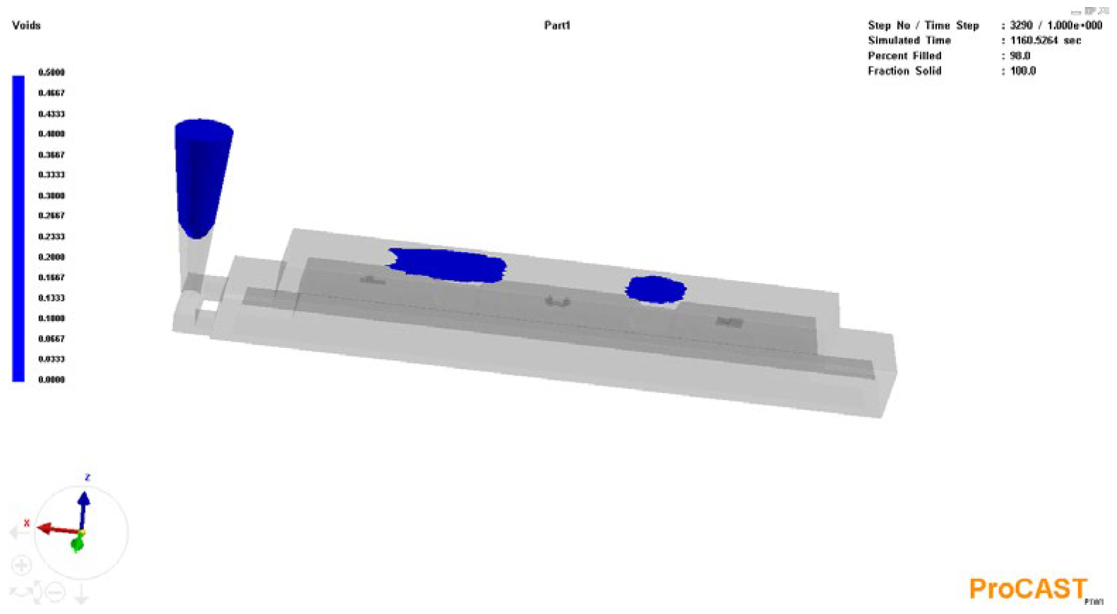
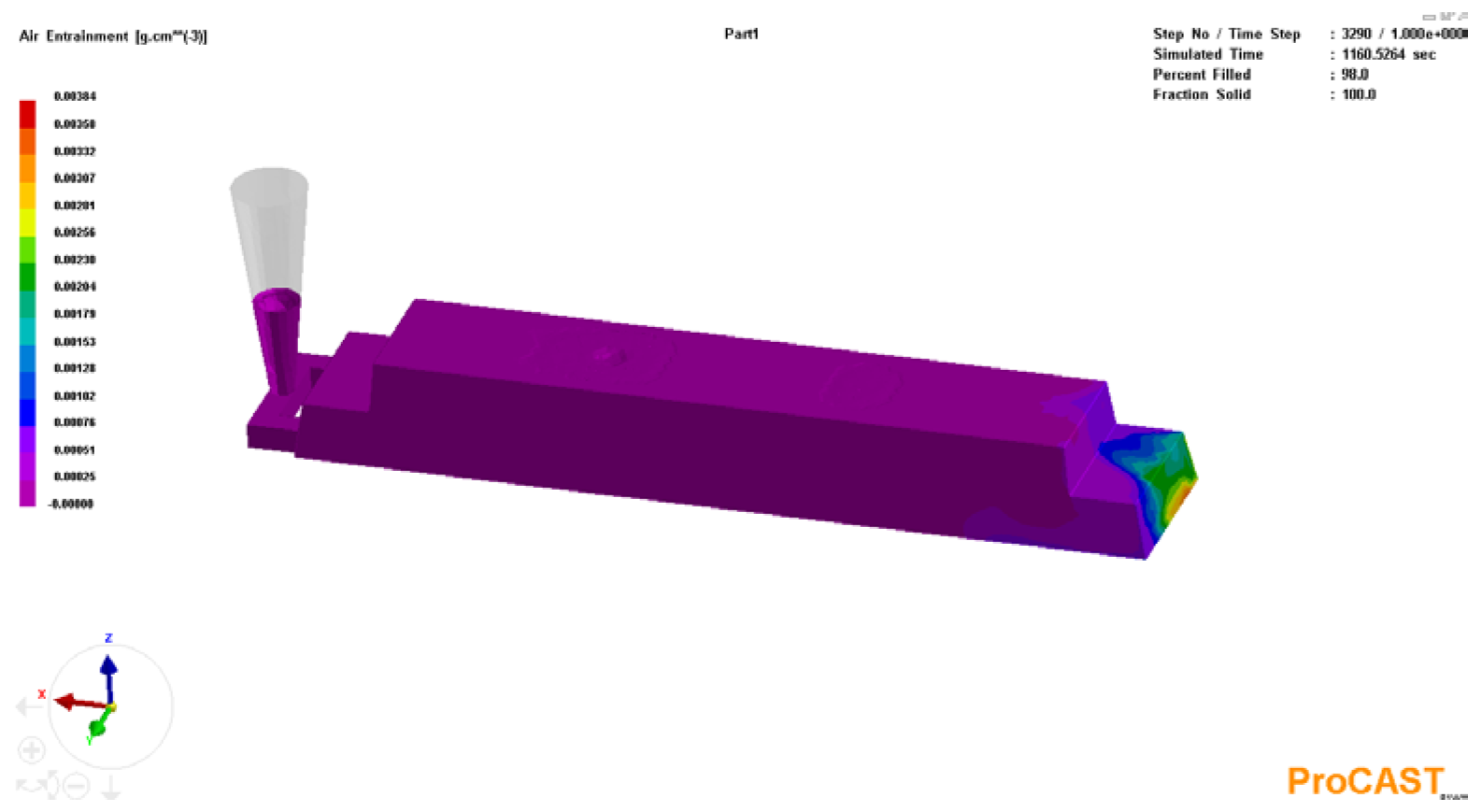
The program allows the visualization of the size and location of voids (Figure 9) and air entrainment (Figure 10).
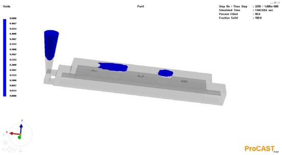
Figure 9.
Visualization of the voids formed.
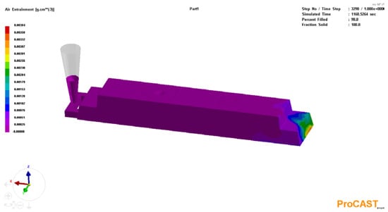
Figure 10.
Visualization of air entrainment.
The results of the simulations of the casting mold filling process show that the voids are entirely localized within the gating system and at the hot spots. The simulation results indicate that no porosity occurs within the casting volume due to metal shrinkage.
The visualization of air entrainment in castings shows the risk of gas defects formation in the casting volume. Air entrainment in castings occurs because of air or gases being trapped in the molten metal during the casting process. This process can result in defects in the casting, such as porosity and areas with reduced mechanical properties.
4. Discussion
The results of the simulation of the gravity filling process provide important information on the behavior of the liquid metal (EN-GJL-250) during its movement in the mold cavity. A key observation is that the formation of voids is limited to the gating system and thermal nodes, with no shrinkage-induced porosity observed in the casting volume. This result suggests that cooling conditions should be properly set to compensate for the volumetric shrinkage of the metal during crystallization. The simulation results indicate a possible risk of gas entrainment in the casting volume, which may be due to errors in the design of the gating system and the high pouring speed of the casting. Hot spots—areas of slower cooling rates—show localized voids, which is typical, but they can be eliminated by optimizing the gate system or by placing coolers. Overall, the results indicate a need to correct the design of the gating system and the corresponding pouring speed of the sand mold. The software allows for the very accurate prediction of possible defects in the casting, significantly reducing the time and costs of designing and manufacturing foundry equipment.
5. Conclusions
Based on the simulation results, it can be concluded that the proposed gating system effectively prevents shrinkage-induced porosity in the casting volume, with the voids being limited to the gating system and hot spots. To improve the casting quality, it is recommended that an open riser be placed at the identified hot spots to assist proper feeding during crystallization and eliminate localized void formation. Due to the risk of air entrainment in the casting volume, we suggest providing additional ventilation in the casting mold and reducing the pouring speed. The software allows for very accurate predictions of possible defects in the casting, significantly reducing the time and costs required to design and manufacture foundry equipment.
Author Contributions
Conceptualization, K.P. and A.N.; methodology, A.M.; software, K.P.; validation, K.P. and A.N.; formal analysis, K.P.; investigation, K.P.; resources, A.N.; data curation, A.M.; writing—original draft preparation, K.P.; writing—review and editing, A.M.; visualization, K.P.; supervision, A.N.; project administration, A.M.; funding acquisition, A.N. All authors have read and agreed to the published version of the manuscript.
Funding
Not applicable.
Institutional Review Board Statement
Not applicable.
Informed Consent Statement
Not applicable.
Data Availability Statement
Data will be available on request.
Acknowledgments
The authors would like to thank the Research and Development Sector at the Technical University of Sofia for the financial support.
Conflicts of Interest
The authors declare no conflicts of interest.
References
- Lan, P.; Zhang, J. Study on the mechanical behaviors of grey iron mould by simulation and experiment. Mater. Des. 2014, 53, 822–829. [Google Scholar] [CrossRef]
- Srinivasulu, K.R. Casting Simulation of Cast Iron Rotor Disc using ProCAST. Int. J. Curr. Eng. Technol. 2014, 4, 4091–4094. [Google Scholar]
- Ravi, B. Metal Casting—Computer Aided Design and Analysis; Prentice Hall of India Private Limited: New Delhi, India, 2005; Available online: https://www.researchgate.net/publication/228533440_Computer-aided_casting_method_design_simulation_and_optimization (accessed on 1 May 2025).
- Masoumi, M.; Hu, H.; Hedjazi, J.; Boutorabi, M. Effect of Gating Design on Mold Filling. J. King Saud Univ.—Eng. Sci. 2021, 33, 201–212. [Google Scholar] [CrossRef]
- Shepel, S.V.; Paolucci, S. Numerical simulation of filling and solidification of permanent model casting. Appl. Therm. Eng. 2002, 22, 229–248. [Google Scholar] [CrossRef]
- Ilinca, J.; Hetu, F. Finite element solution of three-dimensional turbulent flows applied to mold-filling problems. Intl. J. Num. Meth. Fluids 2000, 34, 729–750. [Google Scholar] [CrossRef]
- Lemos, C.M. A simple numerical technique for turbulent flows with free surfaces. Intl. J. Num. Meth. Fluids 1992, 15, 127–146. [Google Scholar] [CrossRef]
- Loulou, T.; Artyukhin, E.A.; Bardon, J.P. Estimation of thermal contract resistance during the first stages of metal solidification process: Experimental setup ans results. Int. J. Heat Mass Transfer. 1999, 42, 2129–2142. [Google Scholar] [CrossRef]
- Sulaiman, S.; Hamouda AM, S.; Abedin, S.; Osman, M.R. Simulation of metal filling progress during the casting progress. J. Mater. Process. Technol. 2000, 100, 224–229. [Google Scholar] [CrossRef]
- Diószegi, A.; Svidró, P.; Elmquist, L.; Dugic, I. Defect formation mechanisms in lamellar graphite ıron related to the casting geometry. Int. J. Cast Met. Res. 2016, 29, 279–285. [Google Scholar] [CrossRef]
- Abhilash, E.; Joseph, M.A. Modelling and Simulation of Casting Process: An Overview. Indian Foundry J. 2009, 55, 28–37. [Google Scholar]
- ProCast: Simulate Sand Casting Processes. Available online: https://www.esi-group.com/products/procast/sand-casting-simulation (accessed on 1 May 2025).
- Janerka, K.; Bartocha, D.; Szajnar, J.; Cholewa, M. The influence of different kind of carburizers and carbu-rization on the effectiveness and iron structure. Arch. Metall. Mater. 2007, 52, 467–474. [Google Scholar]
- Haenny, L.; Zambelli, G. The stiffness and modulus of elasticity of grey cast irons. J. Mater. Sci. Lett. 1983, 2, 239–242. [Google Scholar] [CrossRef]
- Gundlach, R.; Meyer, M.; Winardi, L. Influence of Mn and S on the properties of cast iron part III—Testing and analysis. Int. J. Met. 2015, 9, 69–82. [Google Scholar] [CrossRef]
- Behnam, M.J.; Davami, P.; Varahram, N. Effect of cooling rate on microstructure and mechanical properties of gray cast iron. Mater. Sci. Eng. A 2010, 528, 583–588. [Google Scholar] [CrossRef]
- Collini, L.; Nicoletto, G.; Konečná, R. Microstructure and mechanical properties of pearlitic Gray Cast Iron. Mater. Sci. Eng. A 2008, 488, 529–539. [Google Scholar] [CrossRef]
- Machuta, J.; Nová, I. Metallurgy of the Grey Cast Iron for the Automotive Parts. Metallofiz. Noveishie Tekhnol. 2017, 39, 1267–1279. [Google Scholar] [CrossRef]


Disclaimer/Publisher’s Note: The statements, opinions and data contained in all publications are solely those of the individual author(s) and contributor(s) and not of MDPI and/or the editor(s). MDPI and/or the editor(s) disclaim responsibility for any injury to people or property resulting from any ideas, methods, instructions or products referred to in the content. |
© 2025 by the authors. Licensee MDPI, Basel, Switzerland. This article is an open access article distributed under the terms and conditions of the Creative Commons Attribution (CC BY) license (https://creativecommons.org/licenses/by/4.0/).