
Micro-Oscillator as Integrable Sensor for Structure-Borne Ultrasound †

 , , , ,

Abstract
:1. Introduction
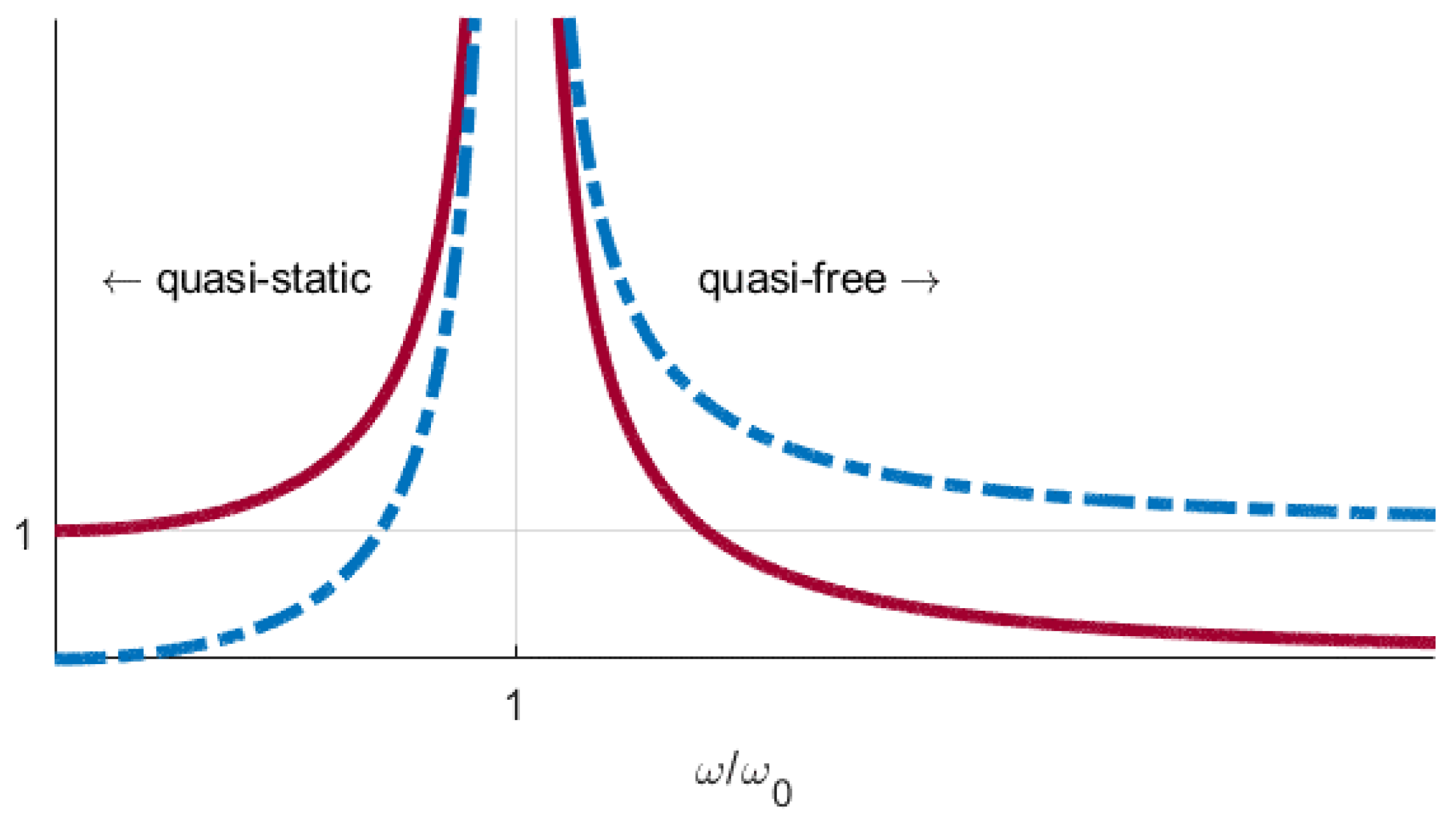
2. Micro-Oscillator Concept
3. Materials and Methods
3.1. Sensor Manufacturing
3.2. Test Setup
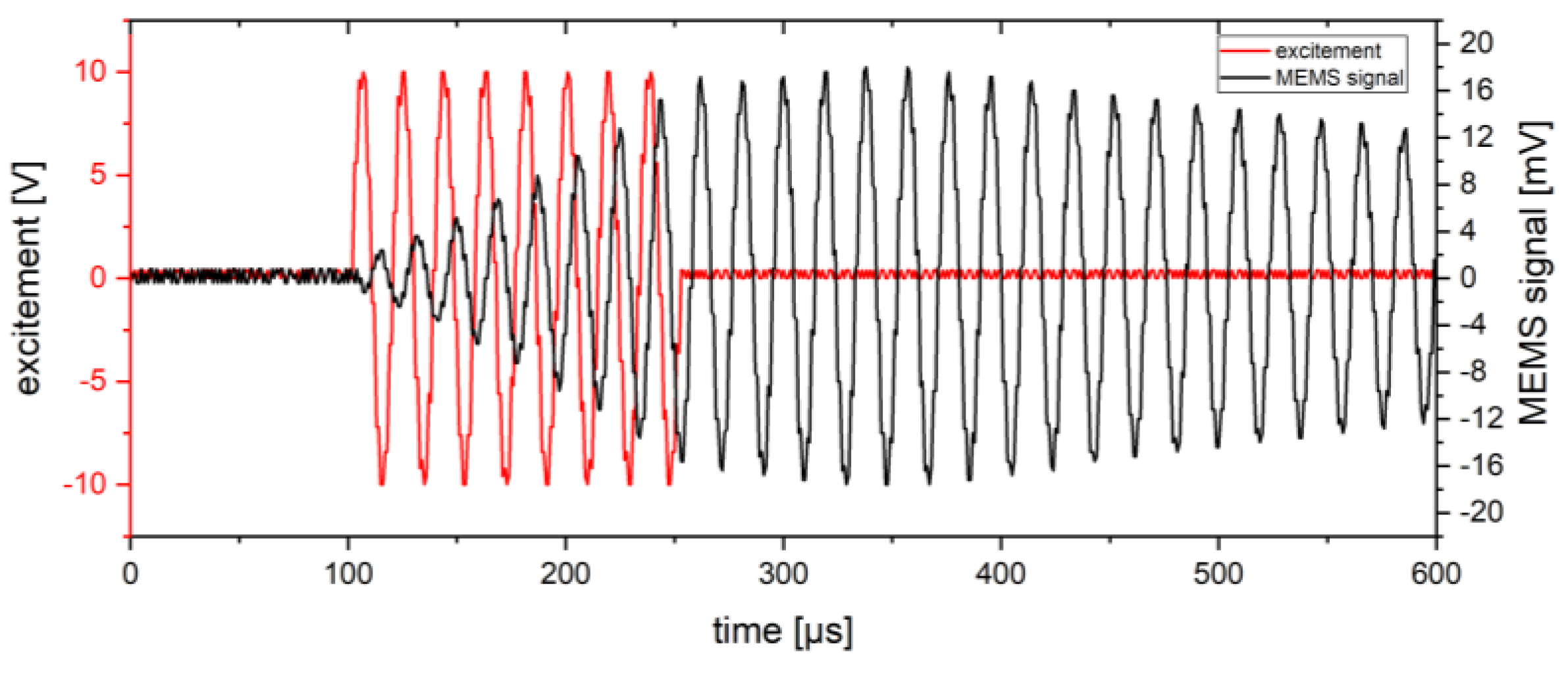
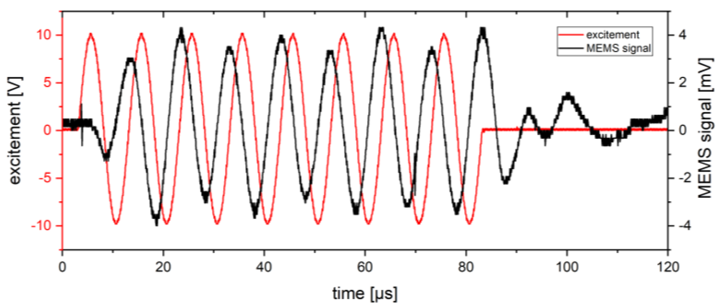
4. Results
5. Discussion and Outlook
Author Contributions
Funding
Institutional Review Board Statement
Informed Consent Statement
Data Availability Statement
Conflicts of Interest
References
- Balageas, G.; Fritzen, C.P.; Güemes, A. Structural Health Monitoring; ISTE Ltd.: London, UK, 2006. [Google Scholar]
- Chai, G.B.; Manikandan, P. Low velocity impact response of fibre-metal laminates—A review. Compos. Struct. 2014, 107, 363–381. [Google Scholar] [CrossRef]
- Rittmeier, L.; Losch, T.; Sinapius, M.; Lammering, R. Investigation on the influence of material interfaces and impedance changes on the propagation of guided waves in laminated steel layers. Procedia Manuf. 2018, 24, 196–202. [Google Scholar] [CrossRef]
- Lammering, R.; Gabbert, U.; Sinapius, M.; Schuster, T.; Wierach, P. (Eds.) Lamb-Wave Based Structural Health Monitoring in Polymer Composites; Springer: Berlin/Heidelberg, Germany, 2017; p. 454. [Google Scholar]
- Büttgenbach, S.; Constantinou, I.; Dietzel, A.; Leester-Schädel, M. Case Studies in Micromechatronics; Springer: Berlin/Heidelberg, Germany, 2020. [Google Scholar]
- Younis, M.I. MEMS Linear and Nonlinear Statics and Dynamics; Springer Science & Business Media: Berlin/Heidelberg, Germany, 2011; ISBN 9781441960207. [Google Scholar]
- Haus, J.N.; Schwerter, M.; Schneider, M.; Gäding, M.; Leester-Schädel, M.; Schmid, U.; Dietzel, A. Robust Pressure Sensor in SOI Technology with Butterfly Wiring for Airfoil Integration. Sensors 2021, 21, 6140. [Google Scholar] [CrossRef] [PubMed]
- Rittmeier, L.; Roloff, T.; Haus, J.; Dietzel, A.; Sinapius, M. Design of a Characterization Environment for a MEMS Ultrasound Sensor under Guided Ultrasonic Wave Excitation. In Proceedings of the 8th International Electronic Conference on Sensors and Applications, Basel, Switzerland, 1–15 November 2021. [Google Scholar] [CrossRef]


Publisher’s Note: MDPI stays neutral with regard to jurisdictional claims in published maps and institutional affiliations. |
© 2021 by the authors. Licensee MDPI, Basel, Switzerland. This article is an open access article distributed under the terms and conditions of the Creative Commons Attribution (CC BY) license (https://creativecommons.org/licenses/by/4.0/).
Share and Cite
Haus, J.N.; Rittmeier, L.; Roloff, T.; Mikhaylenko, A.; Bornemann, S.; Sinapius, M.; Rauter, N.; Lang, W.; Dietzel, A. Micro-Oscillator as Integrable Sensor for Structure-Borne Ultrasound. Eng. Proc. 2021, 10, 81. https://doi.org/10.3390/ecsa-8-11313
Haus JN, Rittmeier L, Roloff T, Mikhaylenko A, Bornemann S, Sinapius M, Rauter N, Lang W, Dietzel A. Micro-Oscillator as Integrable Sensor for Structure-Borne Ultrasound. Engineering Proceedings. 2021; 10(1):81. https://doi.org/10.3390/ecsa-8-11313
Chicago/Turabian StyleHaus, Jan Niklas, Liv Rittmeier, Thomas Roloff, Andrey Mikhaylenko, Sarah Bornemann, Michael Sinapius, Natalie Rauter, Walter Lang, and Andreas Dietzel. 2021. "Micro-Oscillator as Integrable Sensor for Structure-Borne Ultrasound" Engineering Proceedings 10, no. 1: 81. https://doi.org/10.3390/ecsa-8-11313
APA StyleHaus, J. N., Rittmeier, L., Roloff, T., Mikhaylenko, A., Bornemann, S., Sinapius, M., Rauter, N., Lang, W., & Dietzel, A. (2021). Micro-Oscillator as Integrable Sensor for Structure-Borne Ultrasound. Engineering Proceedings, 10(1), 81. https://doi.org/10.3390/ecsa-8-11313