
Tapered Optical Fiber for Hydrogen Sensing Application Based on Molybdenum Trioxide (MoO3) †

 ,
,  , ,
, ,  ,
, 
Abstract
:1. Introduction
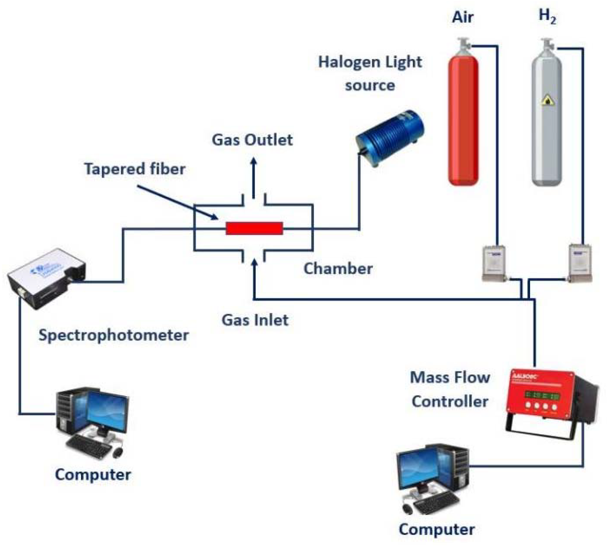
2. Experimental
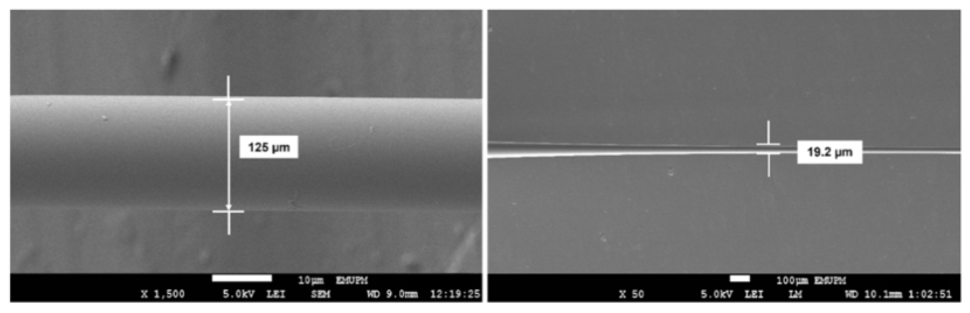
2.1. Tapering Process of Optical Fiber
2.2. Fabrication of MoO3 on Tapered Optical Fiber
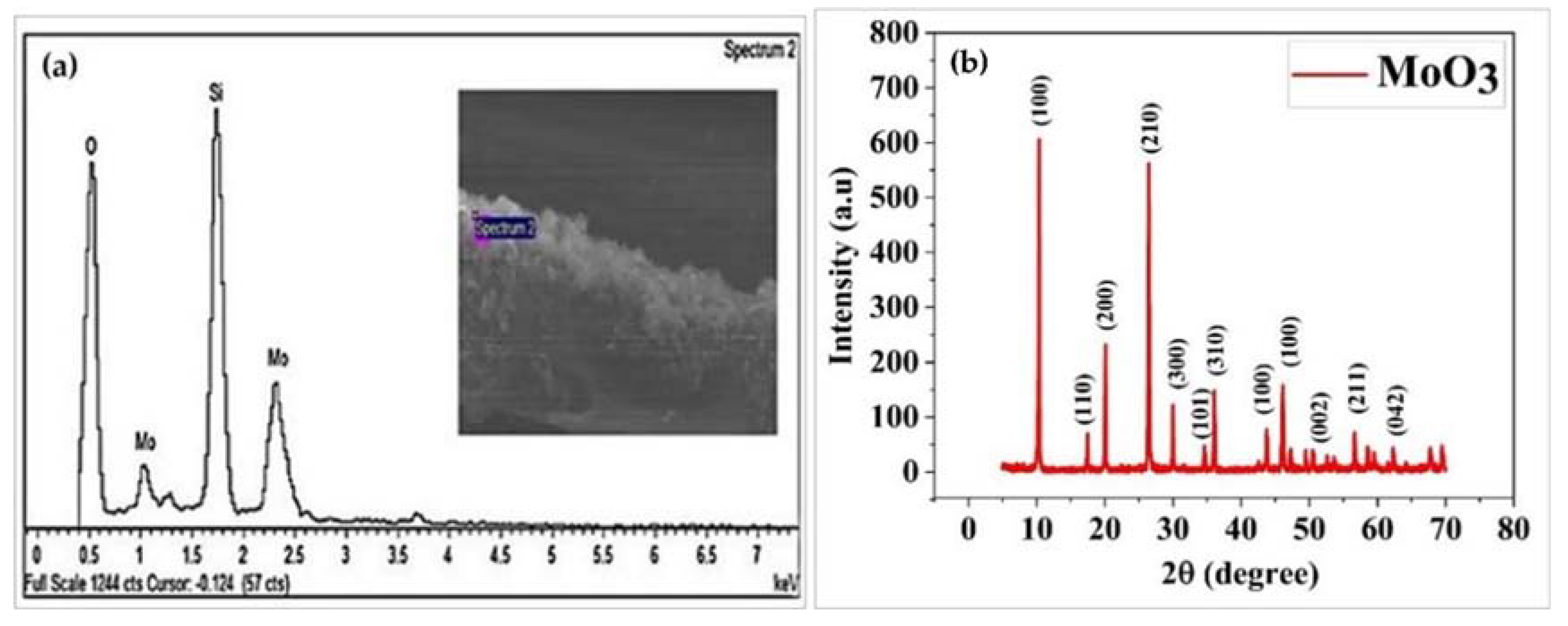
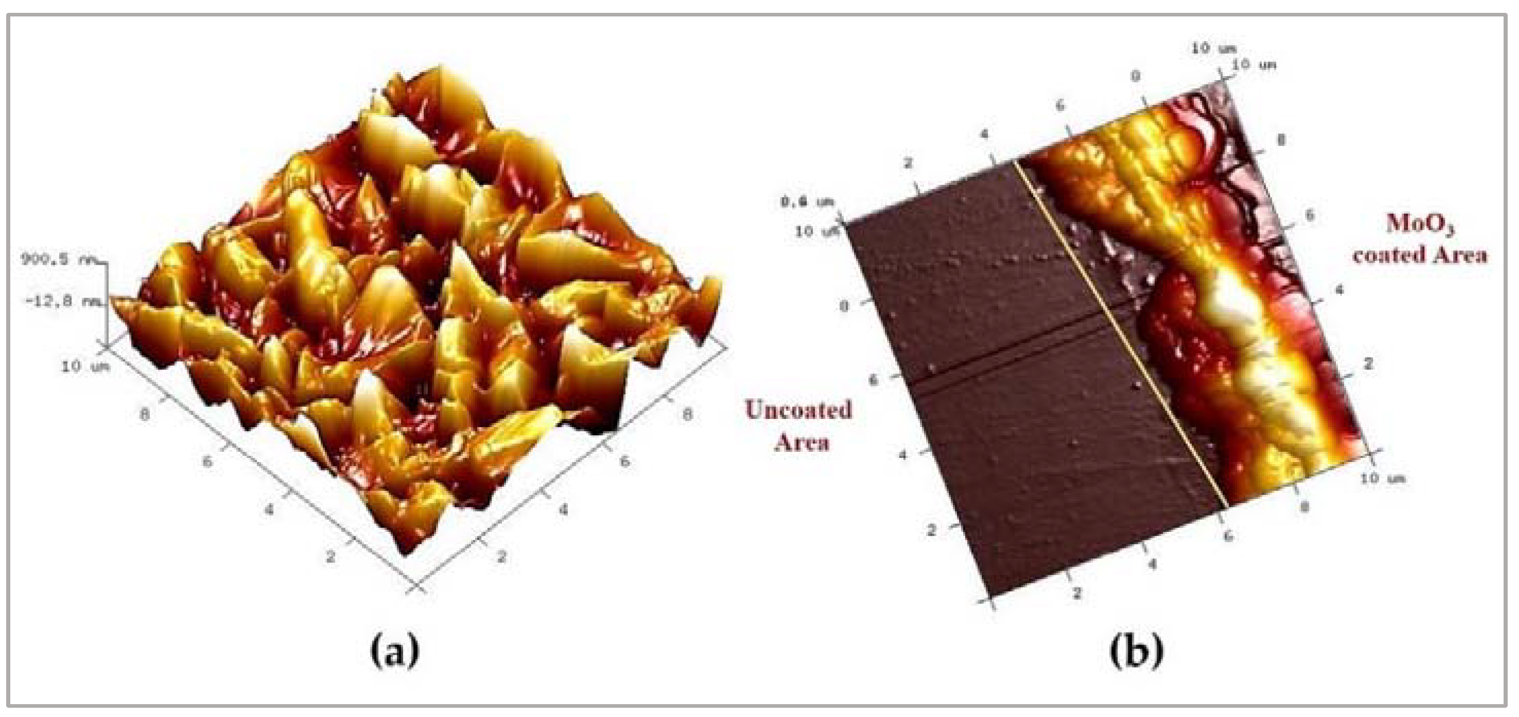
2.3. Structural Characterization of MoO3
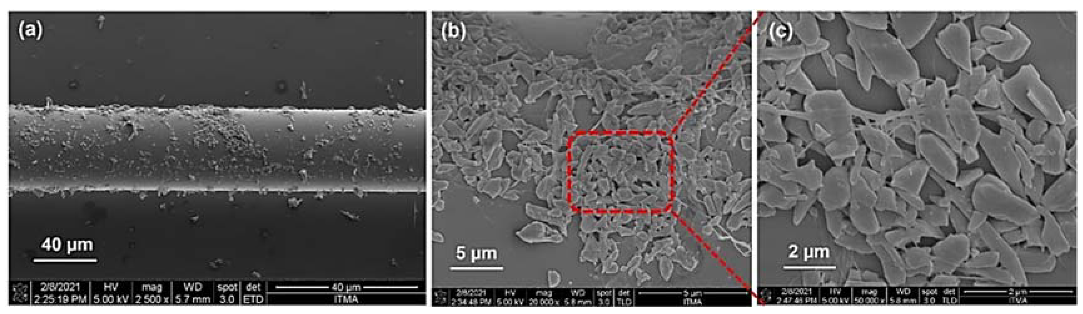
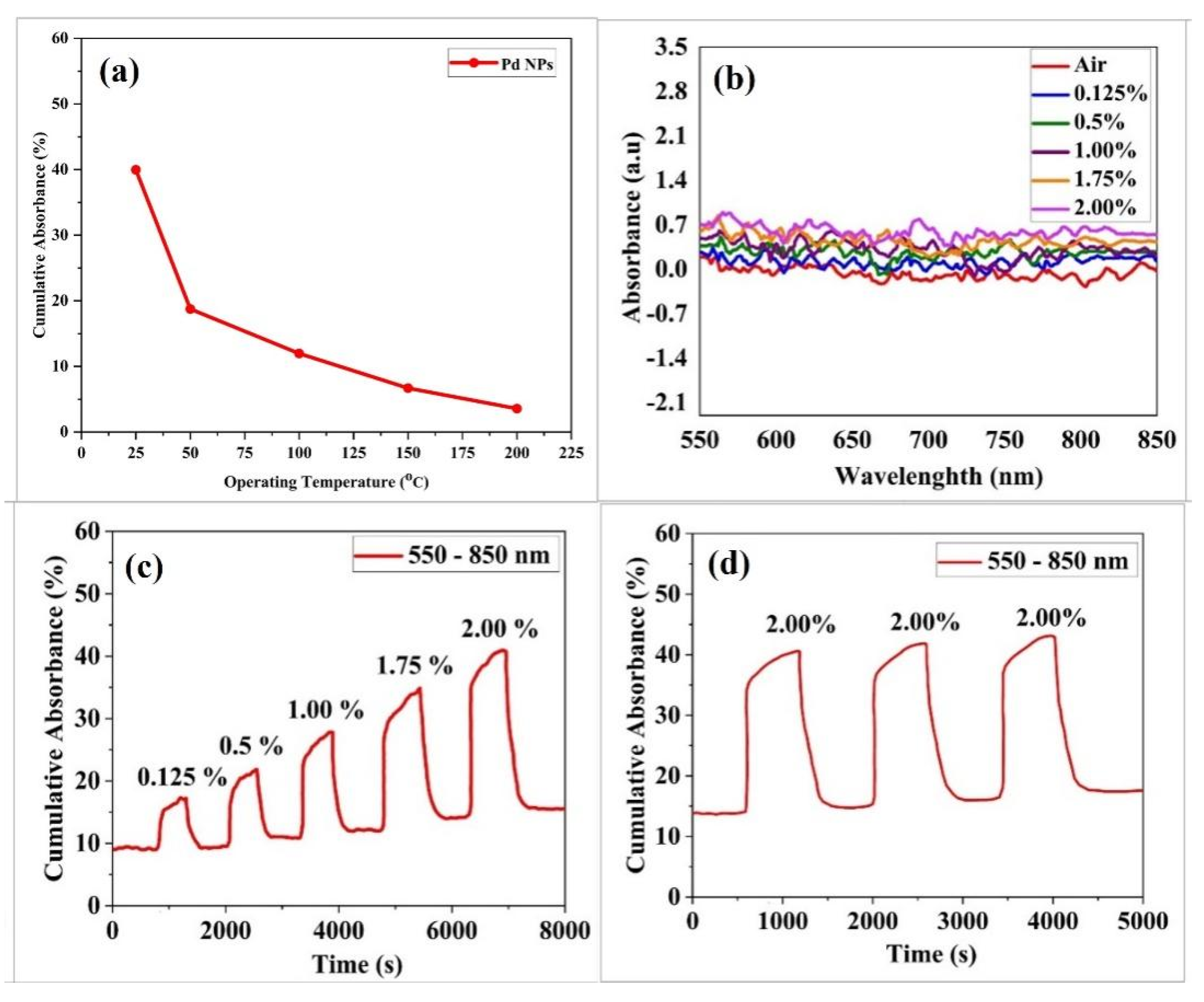
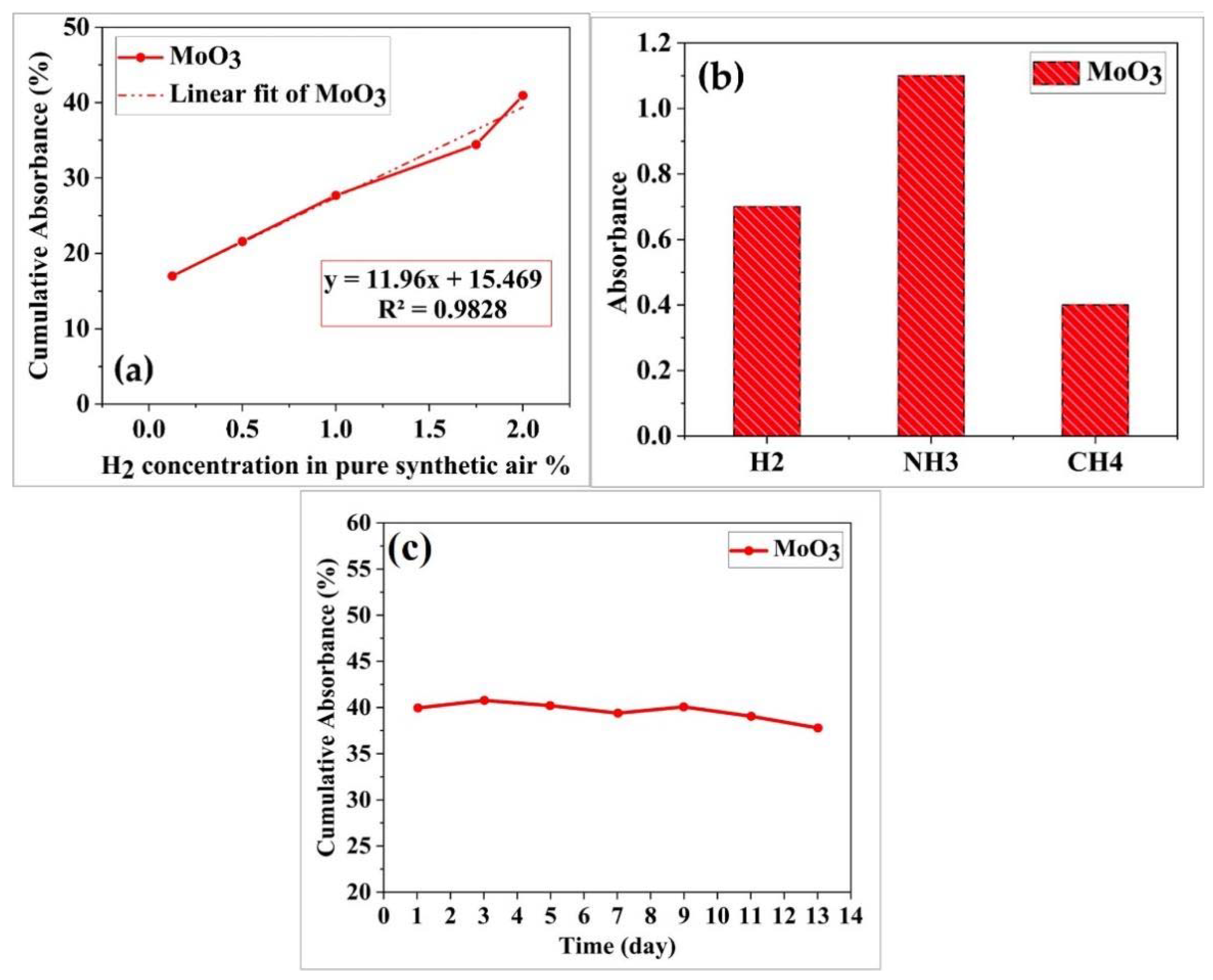
3. Results and Discussion
4. Conclusions
Supplementary Materials
Author Contributions
Funding
Conflicts of Interest
References
- Gahleitner, G. Hydrogen from renewable electricity: An international review of power-to-gas pilot plants for stationary applications. Int. J. Hydrogen Energy 2013, 38, 2039–2061. [Google Scholar] [CrossRef]
- Moradi, R.; Groth, K.M. Hydrogen storage and delivery: Review of the state of the art technologies and risk and reliability analysis. Int. J. Hydrogen Energy 2019, 44, 12254–12269. [Google Scholar] [CrossRef]
- Gurz, M.; Baltacioglu, E.; Hames, Y.; Kaya, K. The meeting of hydrogen and automotive: A review. Int. J. Hydrogen Energy 2017, 42, 23334–23346. [Google Scholar] [CrossRef]
- Sabri, N.; Aljunid, S.A.; Salim, M.S.; Fouad, S. Fiber optic sensors: Short review and applications. In Springer Series in Materials Science; Springer: Berlin/Heidelberg, Germany, 2015; Volume 204, pp. 299–311. [Google Scholar] [CrossRef]
- Wang, H.; Jiang, L.; Xiang, P. Improving the durability of the optical fiber sensor based on strain transfer analysis. Opt. Fiber Technol. 2018, 42, 97–104. [Google Scholar] [CrossRef]
- Yaacob, M.H.; Yu, J.; Latham, K.; Kalantar-Zadeh, K.; Wlodarski, W. Optical hydrogen sensing properties of nanostructured Pd/MoO3 films. Sens. Lett. 2011, 9, 16–20. [Google Scholar] [CrossRef]
- Singh, G.; Singh, R.C. Highly sensitive gas sensor based on Er-doped SnO2 nanostructures and its temperature dependent selectivity towards hydrogen and ethanol. Sens. Actuators B Chem. 2019, 282, 373–383. [Google Scholar] [CrossRef]
- Lavanya, N.; Sekar, C.; Fazio, E.; Neri, F.; Leonardi, S.G.; Neri, G. Development of a selective hydrogen leak sensor based on chemically doped SnO2 for automotive applications. Int. J. Hydrogen Energy 2017, 42, 10645–10655. [Google Scholar] [CrossRef]
- Kumar, G.S.; Xuejin, L.; Du, Y.; Geng, Y.; Hong, X. UV-light enhanced high sensitive hydrogen (H2) sensor based on spherical Au nanoparticles on ZnO nano-structured thin films. J. Alloys Compd. 2019, 798, 467–477. [Google Scholar] [CrossRef]
- Ren, Q.; Cao, Y.Q.; Arulraj, D.; Liu, C.; Wu, D.; Li, W.M.; Li, A.D. Review—Resistive-Type Hydrogen Sensors Based on Zinc Oxide Nanostructures. J. Electrochem. Soc. 2020, 167, 067528. [Google Scholar] [CrossRef]
- Dai, J.; Li, Y.; Ruan, H.; Ye, Z.; Chai, N.; Wang, X.; Yang, M. Fiber optical hydrogen sensor based on wo3-pd2pt-pt nanocomposite films. Nanomaterials 2021, 11, 128. [Google Scholar] [CrossRef] [PubMed]
- Wang, G.; Qin, Y.; Dai, J.; Yang, S.; Ma, Y.; Zou, T.; Roths, J.; Yang, M. Performance-enhanced optical fiber hydrogen sensors based on WO3-Pd2Pt-Pt composite film with controlled optical heating. Opt. Fiber Technol. 2019, 52, 101979. [Google Scholar] [CrossRef]
- Farzi-kahkesh, S.; Fattah, A.; Rahmani, M.B. Synthesis and optimum temperature determination of highly sensitive MoO3-based heterojunction Schottky sensor for hydrogen detection. Microelectron. Eng. 2021, 235, 111453. [Google Scholar] [CrossRef]
- Sajadi, M.; Ranjbar, M.; Rasuli, R. Two-step synthesis of Ag-decorated MoO3 nanotubes, and the effect of hydrogen doping. Appl. Surf. Sci. 2020, 527, 146675. [Google Scholar] [CrossRef]
- Yang, S.; Wang, Z.; Hu, Y.; Luo, X.; Lei, J.; Zhou, D.; Fei, L.; Wang, Y.; Gu, H. Highly responsive room-temperature hydrogen sensing of α-MoO3 nanoribbon membranes. ACS Appl. Mater. Interfaces 2015, 7, 9247–9253. [Google Scholar] [CrossRef] [PubMed]
- Alsaif, M.M.; Balendhran, S.; Field, M.R.; Latham, K.; Wlodarski, W.; Ou, J.Z.; Kalantar-Zadeh, K. Two dimensional α-MoO3 nanoflakes obtained using solvent-assisted grinding and sonication method: Application for H2 gas sensing. Sens. Actuators B Chem. 2014, 192, 196–204. [Google Scholar] [CrossRef]
- Rahmani, M.B.; Keshmiri, S.H.; Yu, J.; Sadek, A.Z.; Al-Mashat, L.; Moafi, A.; Latham, K.; Li, Y.X.; Wlodarski, W.; Kalantar-zadeh, K. Gas sensing properties of thermally evaporated lamellar MoO3. Sens. Actuators B Chem. 2010, 145, 13–19. [Google Scholar] [CrossRef]
- Alkhabet, M.M.; Girei, S.; Paiman, S.; Arsad, N.; Mahdi, M.A.; Yaacob, M.H. Highly Sensitive Hydrogen Sensor Based on Palladium-Coated Tapered Optical Fiber at Room. In Proceedings of the 7th International Electronic Conference on Sensors and Applications, Online, 15–30 November 2020; pp. 3–8. [Google Scholar]
- Dhanavel, S.; Nivethaa, E.A.K.; Dhanapal, K.; Gupta, V.K.; Narayanan, V.; Stephen, A. α-MoO3/polyaniline composite for effective scavenging of Rhodamine B, Congo red and textile dye effluent. RSC Adv. 2016, 6, 28871–28886. [Google Scholar] [CrossRef]
- Sau, S.; Chakraborty, S.; Das, T.; Pal, M. Ethanol Sensing Properties of Nanocrystalline α-MoO3. Front. Mater. 2019, 6, 285. [Google Scholar] [CrossRef]
- Puebla, S.; Mariscal-jim, A.; Munuera, C.; Castellanos-gomez, A. Optical-Based Thickness Measurement of MoO3 Nanosheets. Sensors 2020, 10, 1272. [Google Scholar] [CrossRef] [PubMed]
- Fattah, A.; Rahmani, M.B. Gas Sensing and Structural Properties of a Nano-structure MoO3-based Hydrogen Sensor. Iran. J. Energy Environ. 2019, 10, 230–234. [Google Scholar] [CrossRef]
- Rymarczyk, J.; Czerwosz, E.; Diduszko, R.; Kozłowski, M. The thermal stability of the carbon-palladium films for hydrogen sensor applications. In Photonics Applications in Astronomy, Communications, Industry, and High Energy Physics Experiments; International Society for Optics and Photonics: Bellingham, WA, USA, 2017; Volume 10445, p. 1044550. [Google Scholar]

Publisher’s Note: MDPI stays neutral with regard to jurisdictional claims in published maps and institutional affiliations. |
© 2021 by the authors. Licensee MDPI, Basel, Switzerland. This article is an open access article distributed under the terms and conditions of the Creative Commons Attribution (CC BY) license (https://creativecommons.org/licenses/by/4.0/).
Share and Cite
Alkhabet, M.M.; Girei, S.H.; Paiman, S.; Arsad, N.; Mahdi, M.A.; Yaacob, M.H. Tapered Optical Fiber for Hydrogen Sensing Application Based on Molybdenum Trioxide (MoO3) . Eng. Proc. 2021, 10, 75. https://doi.org/10.3390/ecsa-8-11315
Alkhabet MM, Girei SH, Paiman S, Arsad N, Mahdi MA, Yaacob MH. Tapered Optical Fiber for Hydrogen Sensing Application Based on Molybdenum Trioxide (MoO3) . Engineering Proceedings. 2021; 10(1):75. https://doi.org/10.3390/ecsa-8-11315
Chicago/Turabian StyleAlkhabet, Mohammed Majeed, Saad Hayatu Girei, Suriati Paiman, Norhana Arsad, Mohd Adzir Mahdi, and Mohd Hanif Yaacob. 2021. "Tapered Optical Fiber for Hydrogen Sensing Application Based on Molybdenum Trioxide (MoO3) " Engineering Proceedings 10, no. 1: 75. https://doi.org/10.3390/ecsa-8-11315
APA StyleAlkhabet, M. M., Girei, S. H., Paiman, S., Arsad, N., Mahdi, M. A., & Yaacob, M. H. (2021). Tapered Optical Fiber for Hydrogen Sensing Application Based on Molybdenum Trioxide (MoO3) . Engineering Proceedings, 10(1), 75. https://doi.org/10.3390/ecsa-8-11315