1. Introduction
Nowadays, the development of monitoring systems applied to electrical machines is a challenge for industry and science. The goal is to avoid stoppages in industrial processes with punctual and planned maintenance. In this context, Three-Phase Induction Motors (TIMs) are the main focus of maintenance plans since they are widely applied as a mechanical source in the industrial process [
1,
2,
3,
4].
Among all TIMs components, bearings are crucial in the machine operation once they allow the rotary motion of the rotor while keeping it fixed to the motor structure. Due to their high degree of mobility, they are subject to different types of mechanical flaws [
1,
2,
5]. According to [
6], the TIM failures can be distributed in the bearings, rotor, stator, shaft coupling, external conditions, and other types of fault. Charts prove that the bearings are the components with the highest fault percentage (41%) in induction motors (
Figure 1).
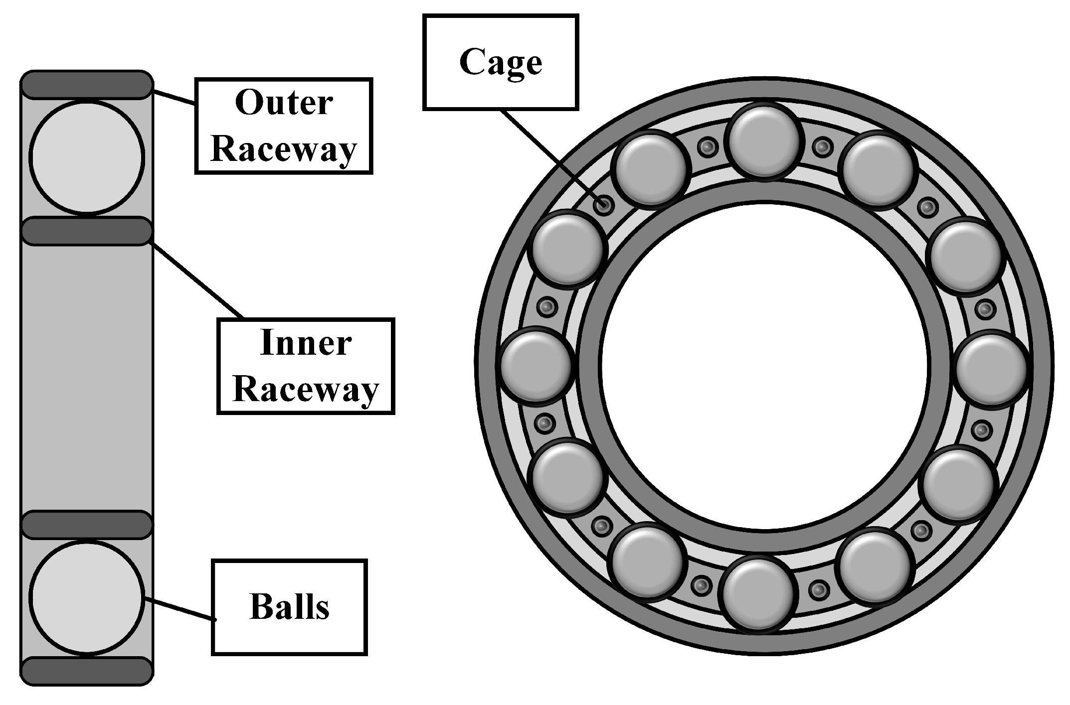
Bearings can be divided into four parts: outer ring, inner ring, cage, and balls (
Figure 2) [
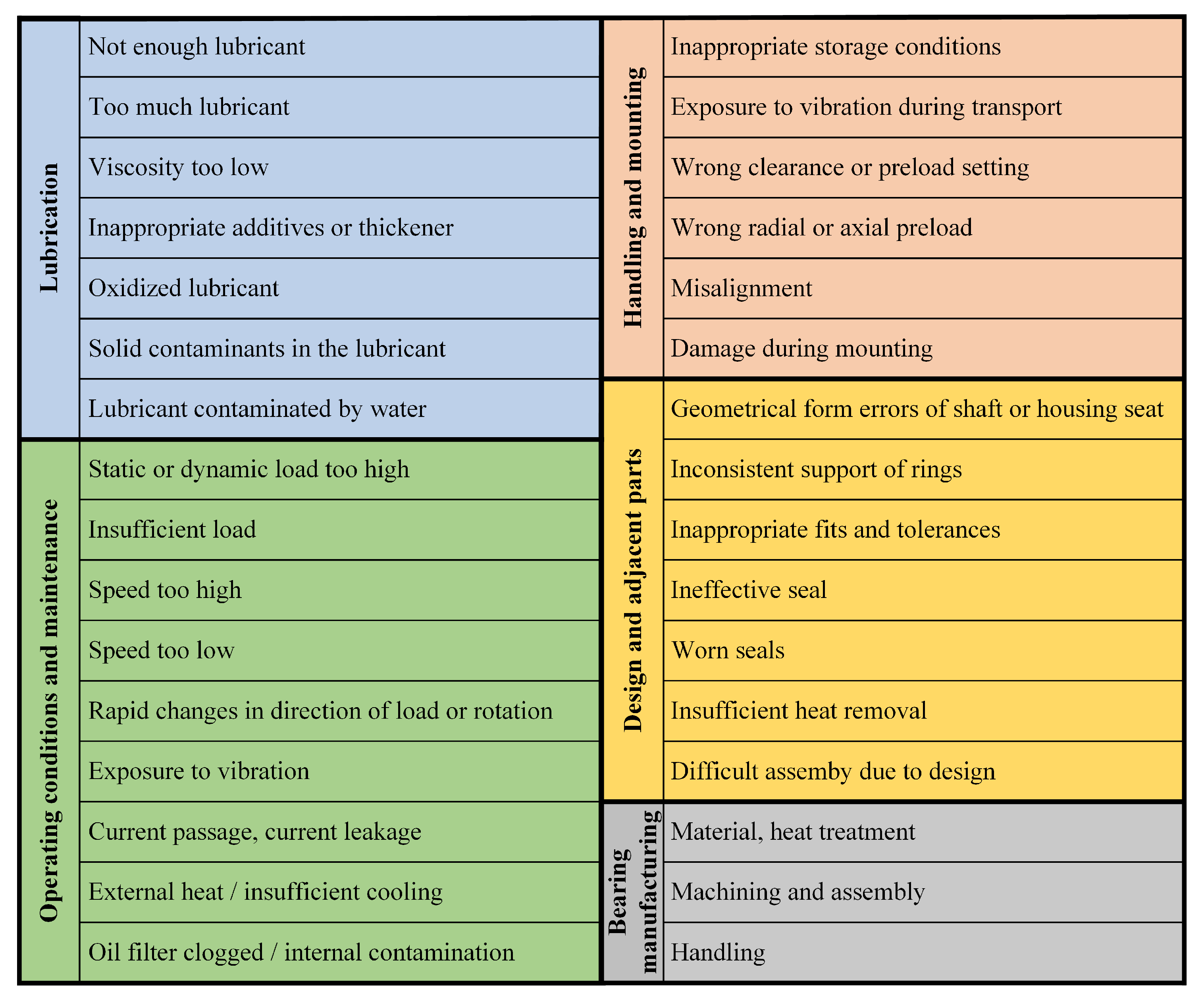
7]. All parts are subject to degradation due to several factors, including operation, maintenance, handling, design, poor lubrication, and manufacturing. These factors are further detailed in
Figure 3 [
8]. Furthermore, these conditions can compromise the integrity of the device, increasing the vibration pattern of the machine, generating eccentricity in the rotor, and elevating the supply current [
7]. Due to their relevance, bearings are the focus of predictive, preventive, and corrective maintenance.
Therefore, this work presented the principal approaches for bearing fault detection: vibration, current, and thermal analysis. Additionally, the following sections describe the dynamic model of the faults for vibration and current signals. Furthermore, finally, the most recent works in this field were introduced and discussed.
2. Bearing Fault Detection by Vibration Analysis
The nominal operation of TIM produces vibrations that are proportional to its rotational speed. However, the existence of non-conformities can change the vibration patterns of the machine. Therefore, vibration analysis stands out as a tool for fault diagnosis and is carried out by applying acceleration sensors [
7,
9,
10].
2.1. Mathematical Models
Based on the constructive elements of the bearings, the failures in this device can be found on the balls, cage, outer raceways, and inner raceways. Just as other types of faults, bearing faults are modeled from sidebands of the rotating frequency of the TIM, i.e., the frequency imposed by the angular velocity of the rotor [
9,
10].
Considering
the diameter of a ball,
the distance between the centers of two opposite balls,
the rotational frequency of the rotor, and
the contact angle between the spheres and the raceways; the sidebands regarding to faults in balls (
), cages (
), outer raceways (
), and inner raceways (
) are determined by the following Equations [
9,
10]:
where
is the number of balls.
2.2. Recent Studies
Recent studies indicates that a critical issue to perform damage detection in bearings is the speed variation, once the mathematical model depends on the velocity of the machine.
In this scenario, Tang et al. (2020) [
11], proposed an approach in which the nonstationary vibration signal was converted from the time domain into a stationary signal in the angle domain with computed order tracking to eliminate speed fluctuations [
11]. Multiple bearing faults under no-load and full-load and a combination of bearing and rotor bar faults are diagnosed with Rational Dilation Wavelet Transforms (RDWT) in [
9]. Ref. [
12] proposed an intelligent system based on k-nearest neighbour (kNN) for diagnosing bearing defects. Hilbert Transform-based enveloping, principal component analysis (PCA), and sequential floating forward selection (SFFS) techniques were used for elimination of the redundancies, selecting the relevant features to perform bearing fault diagnosis. These selected features were the input of the kNN system.
3. Bearing Fault Detection by Current Analysis
Due to the operation and architecture of the TIMs, bearing faults influence the motor supply currents. Therefore, current signature analysis is a widely explored technique in recent studies for fault diagnosis.
3.1. Mathematical Models
As mentioned, bearing failures can be modeled according to dynamic equations. As observed in the last section, a faulty element introduces harmonics into the vibration spectrum of the machine. Additionally, any change in the vibration pattern will proportionally affect the current frequency components [
7,
13].
Considering the vibration fault frequencies
,
,
and
, as the frequency
, the respective fault frequency for current signals
is given by the equation below [
13]:
where
f is the electrical supply frequency.
Although the frequency is essentially related to the multiple harmonics k of the vibration fault frequency , the use of vibration sensors is not always feasible in practice. The application of current sensors is usually more simple, cheap, and non-invasive when compared to accelerometers.
3.2. Recent Studies
Despite being a simple methodology, the current analysis may be subject to harmonics. Furthermore, overload operation can impair the capabilities of the methodology to identify the frequencies amplitudes and, consequently, the bearing faults. In this sense, several works try to improve the efficiency of current analysis by proposing signal processing methods.
In this context, [
14] proposed a new approach to estimate the bearing fault severity based on the air–gap displacement profile. This profile was reconstructed from the mutual inductance variation, which is estimated from a quantitative electrical model that takes the stator current as input. A superposition of multiple Fourier series was used to estimate the severity of the bearing flaw [
14].
Toma et al. (2020) [
10] used a Genetic Algorithm and Machine Learning classifiers to perform bearing fault detection based on current analysis. Multiple characteristic vibration frequencies modulated in the current was investigated in [
15], which proposed a new mathematical model considering the geometry of the damages. A remote monitoring system combined with frequency analysis was proposed by [
13]. Corral et al. (2021) [
16] studied three types of goodness-of-fit (GoFT) tests for current analysis to detect three types of bearing fault.
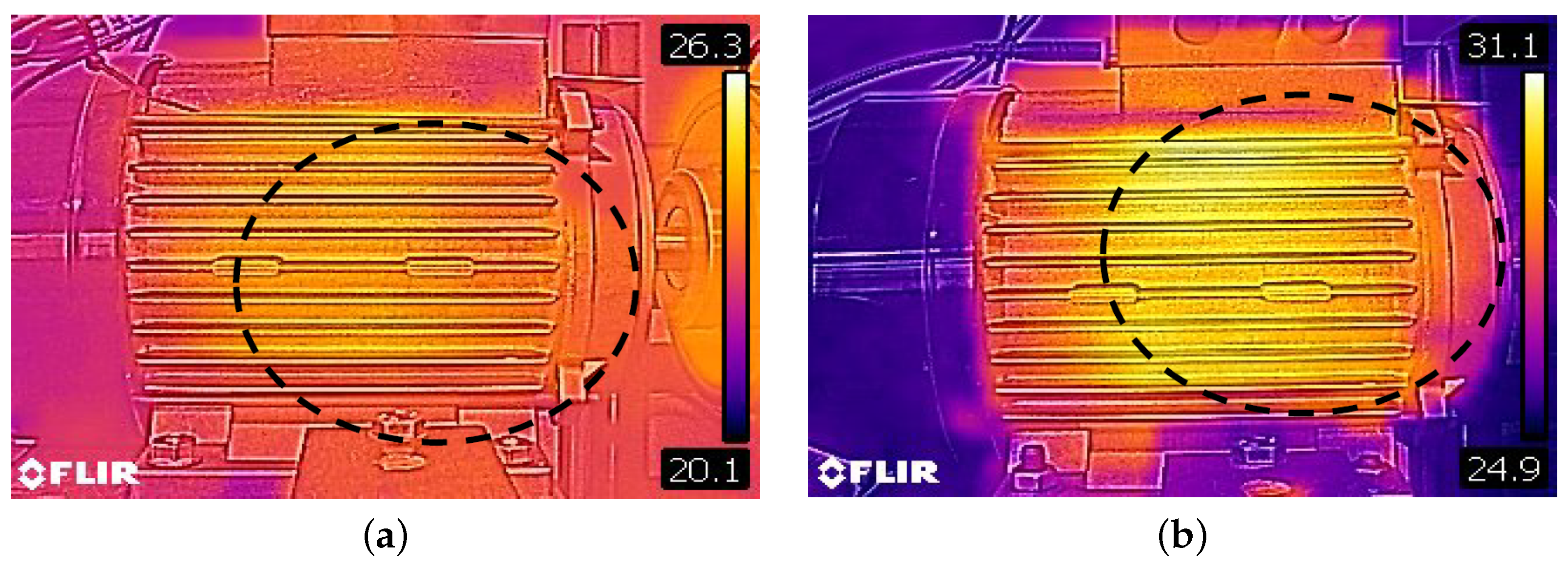
4. Bearing Fault Detection by Infrared Thermal Cameras
Since bearing failures are inherently related to high temperatures, thermal analysis is frequently applied to monitor this equipment. Although its feature extraction is not as effective as other methods, its simplicity and reliability make it a widely used tool [
17]. The basis of this method is to detect the infrared wavelengths emitted by bearing failures.
Figure 4 [
18] illustrates an image of a TIM with a faulty bearing captured by a thermal camera.
Recent Studies
One of the most common issues in Infrared Thermal Analysis is the noise caused by the environment, which impairs the capabilities of distinction of heat spots. Therefore, recent studies focus on improving signal processing techniques to distinguish the heat emitted by the faults from background noise.
In [
6], the discrete wavelet transform was applied for denoising the images captured from different bearing conditions under different speeds and loads. After that, Principal component analysis and Mahalanobis distance (MD) criteria were applied to perform better classification accuracy and less training time compared to conventional algorithms. Thus, PCA-MD method has been used to obtain the optimal feature set as a training classifier for bearing fault detection.
Ammar et al. (2020) [
18] proposed a new approach to improve the capabilities of thermal analysis by proposing a new color model namely Hue, Saturation and Value (HSV). Five segmentation methods (Sobel, Prewitt, Roberts, Canny and Otsu) were used for segmenting the Hue region aiming to highlight the hottest area in the thermal image. After that, the Mean, Mean Square Error, Peak Signal to Noise Ratio, Variance, Standard Deviation, Skewness and Kurtosis were applied to select bearing fault conditions [
18].
In [
19], a histogram-based approach was used to classify the bearing condition under temperature variation. Shao et al. (2021) proposed a rotor-bearing diagnosis under rotating speeds using two-stage parameter transfer [
20]. This imaging processing was based on a scaled exponential linear unit (SELU) and a modified stochastic gradient descent (MSGD), which were applied to construct an enhanced convolutional neural network.
5. Conclusions
In this work, it was presented the bearing fault models for current, vibration, and infrared sensors. State-of-the-art approaches were presented to assist future works to further enhance these systems, and expand the borders of fault detection technology.
Although bearing failures have been extensively investigated in recent years, there are still research gaps that must be explored. For instance, there is a need for systems that can accurately diagnose incipient failures. In addition, the precision of infrared approaches must be improved, as they are not yet able to indicate which bearing element is faulty. Low-cost alternatives for vibration sensors must be proposed as well since traditional accelerometers tend to be expensive. Finally, current sensors have proven to be less sensitive to mechanical bearing faults and less noise tolerant. Therefore, new sensors and signal processing techniques should be developed to overcome this drawback.
Author Contributions
Conceptualization, B.A.d.C. and G.B.L.; investigation R.R.R., G.B.L.; validation A.L.A. and P.J.A.S.; writing-original draft preparation B.A.d.C. and G.B.L.; writing-review and editing P.J.A.S.; supervision A.L.A. and B.A.d.C; project administration A.L.A. and P.J.A.S. All authors have read and agreed to the published version of the manuscript.
Funding
This research received no external funding.
Institutional Review Board Statement
Not applicable.
Informed Consent Statement
Not applicable.
Data Availability Statement
The data presented in this study are available upon reasonable request.
Conflicts of Interest
The authors declare no conflict of interest.
References
- Pandarakone, S.E.; Mizuno, Y.; Nakamura, H. Evaluating the progression and orientation of scratches on outer-raceway bearing using a pattern recognition method. IEEE Trans. Ind. Electron. 2018, 66, 1307–1314. [Google Scholar] [CrossRef]
- Lucena-Junior, J.A.; de Vasconcelos Lima, T.L.; Bruno, G.P.; Brito, A.V.; de Souza Ramos, J.G.G.; Belo, F.A.; Lima-Filho, A.C. Chaos theory using density of maxima applied to the diagnosis of three-phase induction motor bearings failure by sound analysis. Comput. Ind. 2020, 123, 103304. [Google Scholar] [CrossRef]
- Lucas, G.B.; de Castro, B.A.; Rocha, M.A.; Andreoli, A.L. A new acoustic emission-based approach for supply disturbances evaluation in three-phase induction motors. IEEE Trans. Instrum. Meas. 2020, 70, 1–10. [Google Scholar] [CrossRef]
- Glowacz, A.; Glowacz, W.; Glowacz, Z.; Kozik, J. Early fault diagnosis of bearing and stator faults of the single-phase induction motor using acoustic signals. Measurement 2018, 113, 1–9. [Google Scholar] [CrossRef]
- Yu, H.; Ran, Y.; Zhang, G.; Li, X.; Li, B. A time-varying comprehensive dynamic model for the rotor system with multiple bearing faults. J. Sound Vib. 2020, 488, 115650. [Google Scholar] [CrossRef]
- Choudhary, A.; Goyal, D.; Shimi, S.L.; Akula, A. Condition monitoring and fault diagnosis of induction motors: A review. Arch. Comput. Methods Eng. 2019, 26, 1221–1238. [Google Scholar] [CrossRef]
- Faiz, J.; Ghorbanian, V.; Joksimović, G. Fault Diagnosis of Induction Motors; Institution of Engineering and Technology: London, UK, 2017. [Google Scholar]
- SKF. Bearing Damage and Failure Analysis; Technical Report; SKF Group: Gothenburg, Sweden, 2017. [Google Scholar]
- Barusu, M.R.; Deivasigamani, M. Non-invasive vibration measurement for diagnosis of bearing faults in 3-phase Squirrel cage induction motor using microwave sensor. IEEE Sens. J. 2020, 21, 1026–1039. [Google Scholar] [CrossRef]
- Toma, R.N.; Prosvirin, A.E.; Kim, J.M. Bearing fault diagnosis of induction motors using a genetic algorithm and machine learning classifiers. Sensors 2020, 20, 1884. [Google Scholar] [CrossRef] [PubMed] [Green Version]
- Tang, G.; Wang, Y.; Huang, Y.; Liu, N.; He, J. Compound bearing fault detection under varying speed conditions with virtual multichannel signals in angle domain. IEEE Trans. Instrum. Meas. 2020, 69, 5535–5545. [Google Scholar] [CrossRef]
- Goyal, D.; Dhami, S.; Pabla, B. Vibration response-based intelligent non-contact fault diagnosis of bearings. J. Nondestruct. Eval. Diagn. Progn. Eng. Syst. 2021, 4, 021006. [Google Scholar] [CrossRef]
- Jung, J.; Park, Y.; Lee, S.B.; Cho, C.H.; Kim, K.; Wiedenbrug, E.J.; Teska, M. Monitoring journal-bearing faults: Making use of motor current signature analysis for induction motors. IEEE Ind. Appl. Mag. 2017, 23, 12–21. [Google Scholar] [CrossRef]
- Zhang, S.; Wang, B.; Kanemaru, M.; Lin, C.; Liu, D.; Miyoshi, M.; Teo, K.H.; Habetler, T.G. Model-based analysis and quantification of bearing faults in induction machines. IEEE Trans. Ind. Appl. 2020, 56, 2158–2170. [Google Scholar] [CrossRef]
- Qiu, C.; Wu, X.; Xu, C.; Qiu, X.; Xue, Z. An Approximate Estimation Approach of Fault Size for Spalled Ball Bearing in Induction Motor by Tracking Multiple Vibration Frequencies in Current. Sensors 2020, 20, 1631. [Google Scholar] [CrossRef] [PubMed] [Green Version]
- Aviña-Corral, V.; Rangel-Magdaleno, J.; Morales-Perez, C.; Hernandez, J. Bearing Fault Detection in Adjustable Speed Drive-Powered Induction Machine by Using Motor Current Signature Analysis and Goodness-of-Fit Tests. IEEE Trans. Ind. Inform. 2021, 17, 8265–8274. [Google Scholar] [CrossRef]
- Choudhary, A.; Goyal, D.; Letha, S.S. Infrared thermography-based fault diagnosis of induction motor bearings using machine learning. IEEE Sens. J. 2020, 21, 1727–1734. [Google Scholar] [CrossRef]
- Al-Musawi, A.K.; Anayi, F.; Packianather, M. Three-phase induction motor fault detection based on thermal image segmentation. Infrared Phy. Technol. 2020, 104, 103140. [Google Scholar] [CrossRef]
- Khamisan, N.; Ghazali, K.H.; Almisreb, A.; Zin, A.H.M. Histogram-based of Healthy and Unhealthy Bearing Monitoring in Induction Motor by Using Thermal Camera. J. Telecommun. Electron. Comput. Eng. 2018, 10, 31–35. [Google Scholar]
- Shao, H.; Li, W.; Xia, M.; Zhang, Y.; Shen, C.; Williams, D.; Kennedy, A.; De Silva, C.W. Fault diagnosis of a rotor-bearing system under variable rotating speeds using two-stage parameter transfer and infrared thermal images. IEEE Trans. Instrum. Meas. 2021, 70, 1–11. [Google Scholar] [CrossRef]
| Publisher’s Note: MDPI stays neutral with regard to jurisdictional claims in published maps and institutional affiliations. |
© 2021 by the authors. Licensee MDPI, Basel, Switzerland. This article is an open access article distributed under the terms and conditions of the Creative Commons Attribution (CC BY) license (https://creativecommons.org/licenses/by/4.0/).


 ,
, 