Abstract
Human gait analysis is a growing field of research interest in medical treatment, sports training and structural health monitoring. In our study, we propose a low-cost insole design with wearable sensors based on piezoelectric discs (PZT) and an inertial measurement unit (IMU) to acquire the human gait. The sensors are placed at three points of a shoe sole: toe, metatarsal and heel. The human gait obtained from such an insole layout is significantly affected by plantar pressure distribution and alignment of the feet. The PZT sensors give an insight into the pressure map under the feet, and the IMUs record projection and orientation of the feet.
1. Introduction
1.1. Human Gait
Human gait analysis is the study of a graphical representation of human motion to understand the condition of human muscles, mechanics and fitness. It helps in the prevention, treatment and diagnosis of many diseases, sports training and improvement of postures [1]. The neurological and musculoskeletal illnesses, occuring due to aging, Parkinson’s, thrombosis, stroke and diabetes, affect the stride characteristics and human gait quality at the same time: They lead to a decrease in stride length, shuffling steps, fall risk or impaired gait initiation [2,3,4,5,6]. There are primarily two methods of gait analysis: video and image processing-based and sensors-based. Video/image processing systems capture 3D data of the subject’s gait through one or more highly accurate optic sensors and use digital image processing to study the recorded visual measurements of the different parameters [2]. In most motion laboratories, this technique is used for the complete analysis of the motion of all body segments. Sensor-based techniques, on the other side, are of two types: non-wearable and wearable sensors. The non-wearable systems refer to sensor arrangements at a specific location, such as floor mats or treadmills. The wearable systems refer to sensors placed on several parts of the human body, such as thighs, feet, ankle, etc., which can monitor movements without being restricted to a fixed location or fixed duration of monitoring; out of which, IMU is the most commonly used wearable sensor for gait monitoring [1,7,8].
1.2. Related Work
In relevance to gait study, our area of focus lies in gait acquisition from wearable sensors placed on shoes. Since footwear is an important part of our daily lives, it provides an important means to assess gait characteristics for not only sick and old but also for athletics training and daily gait monitoring [9,10,11]. The long-term monitoring of gait is an advantage of in-sole sensors compared to video/image processing systems. Shu et al. [6] used a comfortable and high-pressure sensitive textile fabric sensor array at 15 points on the insole to get static and dynamic measurements. Chen et al. [12] used a piezoresistive fabric-based customized sensor array of different sizes. Moris et al. [13] used four different types of sensors and an IMU to acquire gait from the feet movement. Zhao et al. placed an IMU on a shoe behind the ankle to acquire gait data [3]. However, whether there is a correlation in the behavior of IMUs with pressure sensors under the feet is still not investigated for understanding foot movement.
1.3. Proposed Design
In our study, we propose a shoe insole with sensor modules at three points under the feet: toe, metatarsal and heel. Each sensor module has an IMU integrated with a low-cost piezoelectric disc as the pressure sensor, where the sensors are aligned on the same axis. With our proposed set-up of co-located piezoelectric disc and IMU, an array of such sensor modules is introduced, where at each measurement point and instant, plantar pressure, as well as orientation, and linear and rotational movement of the feet are captured. This study promises a large amount of data collection from multiple low-cost sensors over a long time, specifically to portray foot motion. From our study of multiple IMUs, we expect to figure out the right location to place IMUs inside the sole for gait applications. The multiple piezo sensors will provide an estimate of high pressure and low-pressure points across the feet, which will be useful for the optimization of both energy harvesting applications and gait analysis.
2. Sensors
2.1. Piezoelectric Sensors
Piezoelectricity is a property of certain dielectric materials: When a force or pressure is exerted on such a material, the mechanical deformation displaces charges on its surface, which is measured as voltage (direct piezoelectric effect) [14]. This characteristic is exhibited by many materials, including quartz crystals, semi-crystalline polyvinylidene polymer, polycrystalline piezoceramic. In our project, we use Lead Zirconate Titanate i.e., PZT. It is widely used due to high dielectric values ( up to 3400 by PZT-5H and up to 1700 by PZT-5A [14]), reliability and stablility amongst all piezoceramics. Furthermore, PZTs are physically strong, chemically inert, low-cost, light-weight and easy to implement.
2.2. IMU Sensors
Inertial measurement units include accelerometers, gyroscopes and even magnetometers. They are used to measure the acceleration and orientation of an object. In most IMUs, there are three axes with gyroscopes, three axes with accelerometers and a computer for coordinate conversion to constitute an IMU for measuring the information of the carrier [1]. When placed on the feet for the purpose of gait analysis, the accelerometer gives the change of velocity of the feet [15]. The gyroscope gives the details of the orientation and posture of feet by measuring its angular rate [1,16], from which the angular velocity and angle of feet during the motion can be derived.
3. Methodology
3.1. Hardware Design
An aluminum structure was designed to be placed at the three positions inside the shoe sole. Figure 1 shows its design with the positions of the sensors. The diameter of the inner sub-structure is 2.5 cm, and the diameter of the outer one is 3 cm. The whole set-up was constructed in such a way that it keeps the IMU on the PCB and PZT discs together on the same axis. The IMU is placed inside the inner sub-structure, and the piezo is placed in the outer one. Due to its metallic structure, it keeps the sensors safe without any possibility of cracks. The integrated aluminum structures are positioned at the mentioned three points in the left shoe (Figure 2).
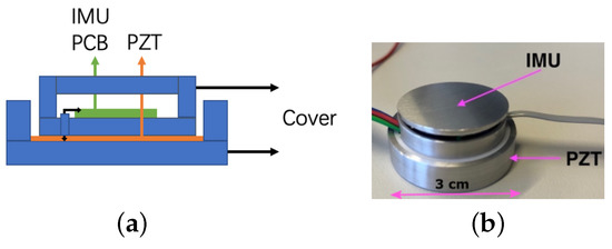
Figure 1.
Structure design: (a) schematic and (b) final structure.
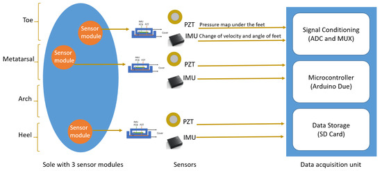
Figure 2.
Framework of the sole layout with multiple sensor modules and data acquisition unit.
We use PZT discs from Murata Electronics. For each disc, the diameter is 12 mm and the resonance frequency is 9.0 kHz [17]. The BMI270 from Bosch is used as the IMU [18]. In the shoe application, the PZT signal is related to plantar pressure distribution, where positive peaks are generated while striking the ground and negative peaks are generated when the feet are lifted from the ground. The IMU signal in the x-direction defines the walking direction of the person, in the y-direction defines diversion of the feet either left or right from the straight path and in the z-direction defines the lifting of the feet from the ground. The gait signals of three people with different weights are measured with each person taking 10 steps for roughly around 10–15 s; each foot taking 5 steps. The PZT and IMU in a sensor module interprets the 5 steps in a different manner, and whether there is a correlation between the sensors will be discussed in detail in further sections. Table 1 gives details of the three subjects.

Table 1.
Information about the three subjects.
3.2. Data Acquisition
Due to the body weight and foot striking the ground, each PZT disc experiences mechanical deformation, which is measured in the form of voltage (V). The microcontroller (MCU) senses this change and acquires the analog data type from multiple PZT discs via an analog to digital converter (ADC) module. On the other hand, the IMU senses the movement of the feet and measures the change of velocity () and degree of rotation (deg) in a binary data type. For reading from multiple IMUs and connecting to the same address of MCU, a multiplexer is used.
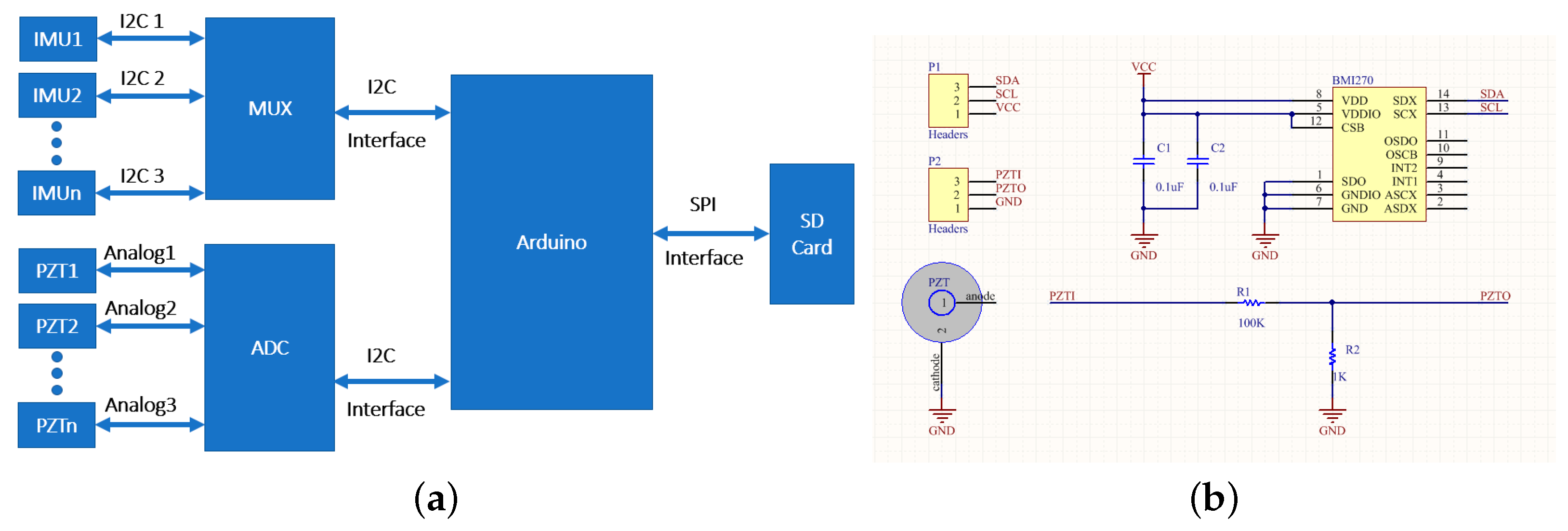
Figure 3a shows the block diagram for data acquisition connection from the sensors to the SD card. The ADC module ADS115 is used to obtain the accurate piezo data using an analog port and multiplexer TCA9548A to acquire data from all the IMUs (Figure 3a). The I2C interface is used between the multiplexer and the micro-controller Arduino Due (A-Due) and between ADC and A-Due. For data storage, an SD card is connected to A-Due through the SPI interface. A-Due performs two tasks at the same time. First, it will acquire data from the array of sensors, and secondly, it will save the acquired data directly on the SD card to facilitate subsequent data analysis. It is to be noted that the simultaneous reading and storing of the accurate data of the multiple sensors limits the sampling rate. The sampling rate of the data acquisition system without the SD card module is 30 Sa for three sensor modules. Because the MCU has to create a file in the SD Card first and store the data, the transmission speed in the initial stage is slowed down. Therefore, with the SD card, the sampling rate drops to 7 Sa to store the experimental data. The electrical connection on the PCB with sensors, multiplexers and ADC is shown in Figure 3b.
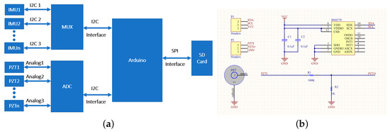
Figure 3.
(a) Data acquisition connection and (b) electrical connections of the sensors inside the structure.
4. Results and Discussion
4.1. Gait Signal from Piezo Sensors
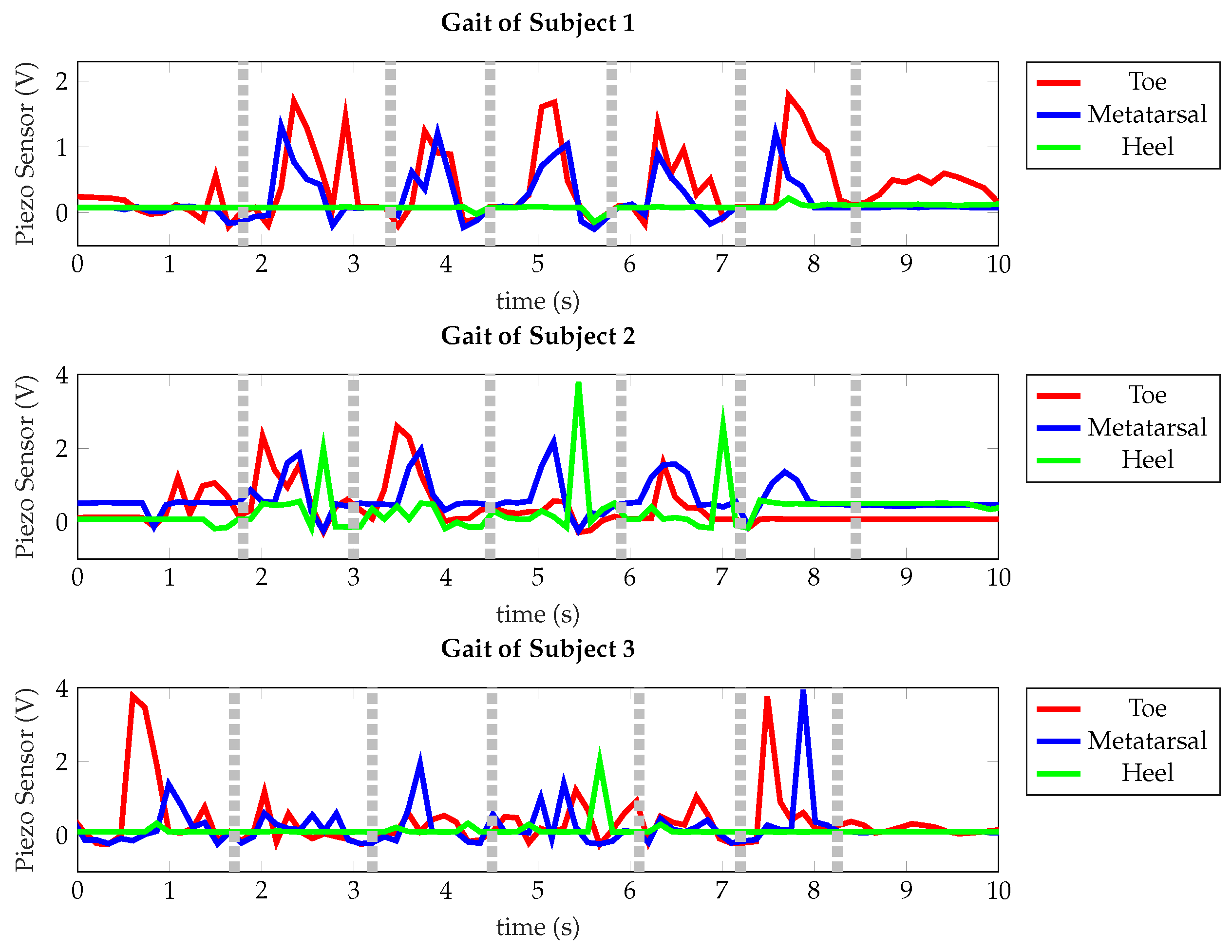
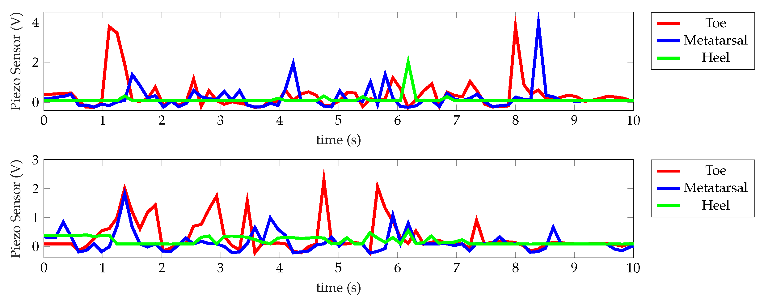
Figure 4 shows the gait measurements of three subjects. As described in Section 3.1, the expected five steps are observed in each gait with roughly five stride regions, separated by dotted lines as a guide to the eyes, depending on the pressure exerted and pronation while walking. The number of peaks generally implies the number of strikes with the ground, but the peaks are not prominent at all points of the feet. It is to be noted that each individual has a different walking frequency and different points of contact with the ground. In general, the walking pattern of an individual is expected to strike the ground in the order heel, arch, metatarsal and toe. It was observed that subject 1 has no heel contact and mainly walks, putting pressure on the toe and metatarsal. Subjects 2 and 3, in contrast, put pressure on their metatarsal points, where it is observed that subject 2 has more pressure points on metatarsal than on toe and heel. On the other hand, subject 3 puts more pressure on the heel and metatarsal points while starting and ending the walk. The desired striking order as assumed (heel, arch, metatarsal and toe) and real gaits of individuals as shown in Figure 4 tend to differ depending on plantar pressure distribution, which is affected by the body pressure on the feet, as well as force used to strike the ground [15,16,19,20,21,22]. The gait pattern varies from time to time when the same person walks in the same pattern. It is shown in Figure 5 that the number, frequency and magnitude of peaks are different for the same individual walking at two instances. These intra-individual variations are likely to occur in daily situations, which makes the gait study not only interesting but also complicated to assess.

Figure 4.
Gait of three people.
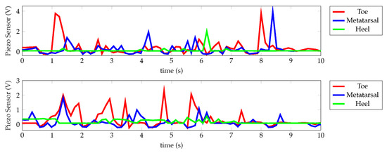
Figure 5.
Gait of subject 3 at different instances.
4.2. Gait Signal from IMU Sensors
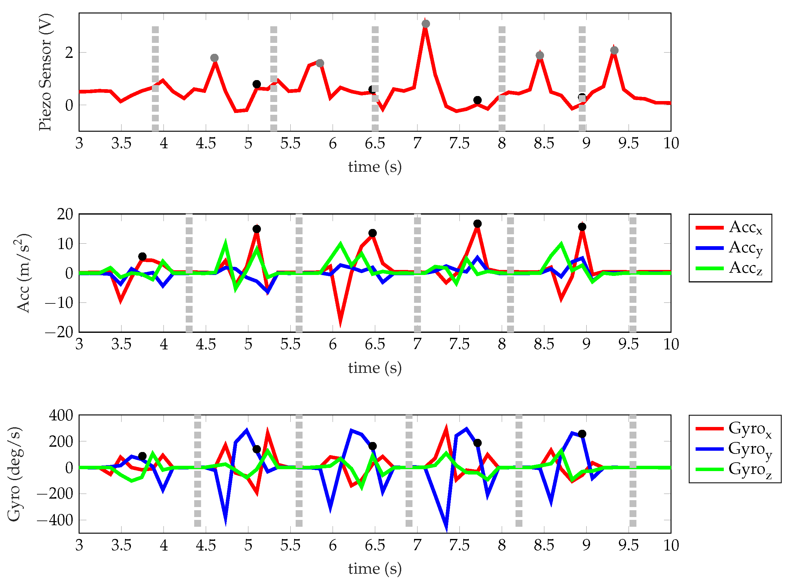
In Figure 6, the IMU signals obtained from accelerometer and gyroscope data at the metatarsal are shown to relate with respect to the signal obtained from the piezo sensor at the same position. The five stride regions are better distinguishable in the accelerometers and gyroscopes than the PZTs. Therefore, the IMU is a better choice for step identification of an individual than piezo sensors. The IMU data helped to identify the peaks occurring while striking the ground, which are gray circles in the figure below. The linear and rotational movement graphs repeat after a certain interval. Their amplitudes are inconsistent, which depends on the way with which the feet are lifted to strike the ground. As the feet take the next step, the acceleration across the x and z-directions changes due to forward movement and lifting of the feet. The change of positions in these two directions is more prominent than that of the y-direction, which is obvious. For the gyro data, the angular changes are more distinct in the x and y-directions due to inward or outward landing variations of the feet and plantar rolling over the ground.
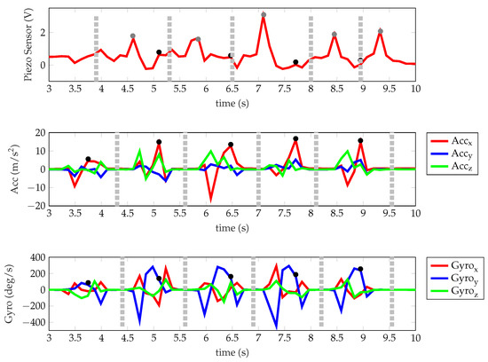
Figure 6.
Signals at the metatarsal of subject 2.
5. Conclusions
In the proposed project, we have designed an insole structure with IMU and piezo sensors integrated together to obtain the gait of an individual at three points of the sole. The set-up collected pressure, linear acceleration and rotational movement of the left feet. We observe that the metatarsal is the most impacted point of the feet, irrespective of the walking pattern of an individual. With an increase in the number of such sensors, a plantar map of high-pressure points and low-pressure points can be estimated. For five strides taken, the IMU signals have five regions to identify each stride with a corresponding peak in the piezo signal.
In the future, we will continue this study to increase the number of subjects and process the signals to correlate the behavior of piezo sensors and IMUs. This shoe design is a promising idea to examine the gait performance of a patient or an athlete, or a health conscious individual with low-cost wearable sensors.
Author Contributions
Conceptualization: N.G.; Methodology: Z.Y. and Y.Q.; Writing: N.G.; Review and Editing: J.K.; Supervision: G.F. All authors have read and agreed to the published version of the manuscript.
Funding
The authors gratefully acknowledge financial support for this work from the Deutsche Forschungsgemeinschaft under GRK2495/A.
Institutional Review Board Statement
Not Applicable.
Informed Consent Statement
Not Applicable.
Data Availability Statement
Not Applicable.
Conflicts of Interest
The authors declare no conflict of interest.
References
- Tao, W.; Liu, T.; Zheng, R.; Feng, H. Gait analysis using wearable sensors. Sensors 2012, 12, 2255–2283. [Google Scholar] [CrossRef] [PubMed]
- Ellis, T.; Cavanaugh, J.T.; Earhart, G.M.; Ford, M.P.; Foreman, K.B.; Dibble, L.E. Which measures of physical function and motor impairment best predict quality of life in Parkinson’s disease? Park. Relat. Disord. 2011, 17, 693–697. [Google Scholar] [CrossRef] [PubMed] [Green Version]
- Zhao, H.; Wang, Z.; Qiu, S.; Shen, Y.; Wang, J. IMU-based gait analysis for rehabilitation assessment of patients with gait disorders. In Proceedings of the 2017 4th International Conference on Systems and Informatics (ICSAI), Hangzhou, Chian, 11–13 November 2017; pp. 622–626. [Google Scholar] [CrossRef]
- Qiu, S.; Wang, Z.; Zhao, H.; Liu, L.; Jiang, Y. Using body-worn sensors for preliminary rehabilitation assessment in stroke victims with gait impairment. IEEE Access 2018, 6, 31249–31258. [Google Scholar] [CrossRef]
- Sijobert, B.; Denys, J.; Coste, C.A.; Geny, C. IMU based detection of freezing of gait and festination in Parkinson’s disease. In Proceedings of the 2014 IEEE 19th International Functional Electrical Stimulation Society Annual Conference (IFESS), Kuala Lumpur, Malaysia, 17–19 September 2014; pp. 1–3. [Google Scholar] [CrossRef]
- Shu, L.; Hua, T.; Wang, Y.; Li, Q.; Feng, D.D.; Tao, X. In-shoe plantar pressure measurement and analysis system based on fabric pressure sensing array. IEEE Trans. Inf. Technol. Biomed. 2010, 14, 767–775. [Google Scholar] [CrossRef] [PubMed] [Green Version]
- Bamberg, S.J.M.; Benbasat, A.Y.; Scarborough, D.M.; Krebs, D.E.; Paradiso, J.A. Gait analysis using a shoe-integrated wireless sensor system. IEEE Trans. Inf. Technol. Biomed. 2008, 12, 413–423. [Google Scholar] [CrossRef] [PubMed] [Green Version]
- Muro-De-La-Herran, A.; Garcia-Zapirain, B.; Mendez-Zorrilla, A. Gait analysis methods: An overview of wearable and non-wearable systems, highlighting clinical applications. Sensors 2014, 14, 3362–3394. [Google Scholar] [CrossRef] [PubMed] [Green Version]
- Queen, R.M.; Haynes, B.B.; Hardaker, W.M.; Garrett, W.E., Jr. Forefoot loading during 3 athletic tasks. Am. J. Sports Med. 2007, 35, 630–636. [Google Scholar] [CrossRef] [PubMed]
- Gioftsidou, A.; Malliou, P.; Pafis, G.; Beneka, A.; Godolias, G.; Maganaris, C.N. The effects of soccer training and timing of balance training on balance ability. Eur. J. Appl. Physiol. 2006, 96, 659–664. [Google Scholar] [CrossRef] [PubMed]
- Chen, M.; Huang, B.; Xu, Y. Intelligent shoes for abnormal gait detection. In Proceedings of the 2008 IEEE International Conference on Robotics and Automation, Pasadena, CA, USA, 19–23 May 2008; pp. 2019–2024. [Google Scholar] [CrossRef]
- Chen, D.; Cai, Y.; Huang, M.C. Customizable pressure sensor array: Design and evaluation. IEEE Sens. J. 2018, 18, 6337–6344. [Google Scholar] [CrossRef]
- Morris, S.J.; Paradiso, J.A. Shoe-integrated sensor system for wireless gait analysis and real-time feedback. In Proceedings of the Second Joint 24th Annual Conference and the Annual Fall Meeting of the Biomedical Engineering Society, Engineering in Medicine and Biology, Houston, TX, USA, 23–26 October 2002; Volume 3, pp. 2468–2469. [Google Scholar] [CrossRef]
- Covaci, C.; Gontean, A. Piezoelectric energy harvesting solutions: A review. Sensors 2020, 20, 3512. [Google Scholar] [CrossRef] [PubMed]
- Zeng, H.; Zhao, Y. Sensing movement: Microsensors for body motion measurement. Sensors 2011, 11, 638–660. [Google Scholar] [CrossRef] [PubMed] [Green Version]
- Catalfamo, P.; Ghoussayni, S.; Ewins, D. Gait event detection on level ground and incline walking using a rate gyroscope. Sensors 2010, 10, 5683–5702. [Google Scholar] [CrossRef] [PubMed] [Green Version]
- Murata Electronics. 7BB-12-9. PD-SU2-C12-90. Available online: https://www.murata.com/en-eu/products/productdetail?partno=7BB-12-9 (accessed on 1 November 2021).
- Bosch Sensortec. BMI270. Revision 1.3, Doc. No. BSGT/BMI207/DS000-05, Tech. Ref. Code 0 273 017 008. Available online: https://www.bosch-sensortec.com/products/motion-sensors/imus/bmi270/ (accessed on 1 November 2021).
- Park, J.S.; Lee, C.M.; Koo, S.M.; Kim, C.H. Gait phase detection using force sensing resistors. IEEE Sens. J. 2020, 20, 6516–6523. [Google Scholar] [CrossRef]
- Hannink, J.; Kautz, T.; Pasluosta, C.F.; Gaßmann, K.G.; Klucken, J.; Eskofier, B.M. Sensor-based gait parameter extraction with deep convolutional neural networks. IEEE J. Biomed. Health Inform. 2016, 21, 85–93. [Google Scholar] [CrossRef] [PubMed] [Green Version]
- Lin, F.; Wang, A.; Zhuang, Y.; Tomita, M.R.; Xu, W. Smart insole: A wearable sensor device for unobtrusive gait monitoring in daily life. IEEE Trans. Ind. Inform. 2016, 12, 2281–2291. [Google Scholar] [CrossRef]
- Mueller, M.J. Application of plantar pressure assessment in footwear and insert design. J. Orthop. Sport. Phys. Ther. 1999, 29, 747–755. [Google Scholar] [CrossRef] [PubMed]


Publisher’s Note: MDPI stays neutral with regard to jurisdictional claims in published maps and institutional affiliations. |
© 2021 by the authors. Licensee MDPI, Basel, Switzerland. This article is an open access article distributed under the terms and conditions of the Creative Commons Attribution (CC BY) license (https://creativecommons.org/licenses/by/4.0/).