
Thermal Shock and Synergistic Plasma and Heat Load Testing of Powder Injection Molding Tungsten-Based Alloys

 ,
,  ,
,  , ,
, ,
Abstract

1. Introduction
2. Materials and Methods
3. Results and Discussion
4. Conclusions
Author Contributions
Funding
Data Availability Statement
Conflicts of Interest
References
- Hirai, T.; Escourbiac, F.; Carpentier-Chouchana, S.; Fedosov, A.; Ferrand, L.; Jokinen, T.; Komarov, V.; Kukushkin, A.; Merola, M.; Mitteau, R.; et al. ITER tungsten divertor design development and qualification program. Fusion Eng. Des. 2013, 88, 1798–1801. [Google Scholar] [CrossRef]
- Pitts, R.; Carpentier, S.; Escourbiac, F.; Hirai, T.; Komarov, V.; Lisgo, S.; Kukushkin, A.; Loarte, A.; Merola, M.; Naik, A.S.; et al. A full tungsten divertor for ITER: Physics issues and design status. J. Nucl. Mater. 2013, 438, S48–S56. [Google Scholar] [CrossRef]
- Pitts, R.; Bonnin, X.; Escourbiac, F.; Frerichs, H.; Gunn, J.; Hirai, T.; Kukushkin, A.; Kaveeva, E.; Miller, M.; Moulton, D.; et al. Physics basis for the first ITER tungsten divertor. Nucl. Mater. Energy 2019, 20, 100696. [Google Scholar] [CrossRef]
- Federici, G.; Biel, W.; Gilbert, M.; Kemp, R.; Taylor, N.; Wenninger, R. European DEMO design strategy and consequences for materials. Nucl. Fusion 2017, 57, 092002. [Google Scholar] [CrossRef]
- Gunn, J.; Carpentier-Chouchana, S.; Escourbiac, F.; Hirai, T.; Panayotis, S.; Pitts, R.; Corre, Y.; Dejarnac, R.; Firdaouss, M.; Kočan, M.; et al. Surface heat loads on the ITER divertor vertical targets. Nucl. Fusion 2017, 57, 046025. [Google Scholar] [CrossRef]
- Linke, J.; Loewenhoff, T.; Massaut, V.; Pintsuk, G.; Ritz, G.; Rödig, M.; Schmidt, A.; Thomser, C.; Uytdenhouwen, I.; Vasechko, V.; et al. Performance of different tungsten grades under transient thermal loads. Nucl. Fusion 2011, 51, 73017. [Google Scholar] [CrossRef]
- Ueda, Y.; Schmid, K.; Balden, M.; Coenen, J.; Loewenhoff, T.; Ito, A.; Hasegawa, A.; Hardie, C.; Porton, M.; Gilbert, M. Baseline high heat flux and plasma facing materials for fusion. Nucl. Fusion 2017, 57, 092006. [Google Scholar] [CrossRef]
- Pintsuk, G. Tungsten as a Plasma-Facing Material. In Comprehensive Nuclear Materials; Elsevier: Amsterdam, The Netherlands, 2012; pp. 551–581. [Google Scholar]
- Philipps, V. Tungsten as material for plasma-facing components in fusion devices. J. Nucl. Mater. 2011, 415, S2–S9. [Google Scholar] [CrossRef]
- Pintsuk, G.; Bobin-Vastra, I.; Constans, S.; Gavila, P.; Rödig, M.; Riccardi, B. Qualification and post-mortem characterization of tungsten mock-ups exposed to cyclic high heat flux loading. Fusion Eng. Des. 2013, 88, 1858–1861. [Google Scholar] [CrossRef]
- Wirtz, M.; Linke, J.; Loewenhoff, T.; Pintsuk, G.; Uytdenhouwen, I. Transient heat load challenges for plasma-facing materials during long-term operation. Nucl. Mater. Energy 2017, 12, 148–155. [Google Scholar] [CrossRef]
- Gago, M.; Kreter, A.; Unterberg, B.; Wirtz, M. Synergistic effects of particle and transient heat loads on ITER-grade tungsten. Phys. Scr. 2020, T171, 014007. [Google Scholar] [CrossRef]
- Gago, M.; Kreter, A.; Unterberg, B.; Wirtz, M. Synergistic and separate effects of plasma and transient heat loads on the microstructure and physical properties of ITER-grade tungsten. Phys. Scr. 2021, 96, 124052. [Google Scholar] [CrossRef]
- Gago, M.; Kreter, A.; Unterberg, B.; Wirtz, M. Bubble Formation in ITER-Grade Tungsten after Exposure to Stationary D/He Plasma and ELM-like Thermal Shocks. J. Nucl. Eng. 2023, 4, 204–212. [Google Scholar] [CrossRef]
- Morgan, T.W.; Balden, M.; Schwarz-Selinger, T.; Li, Y.; Loewenhoff, T.H.; Wirtz, M.; Brezinsek, S.; De Temmerman, G. ITER monoblock performance under lifetime loading conditions in Magnum-PSI. Phys. Scr. 2020, T171, 014065. [Google Scholar] [CrossRef]
- Wirtz, M.; Kreter, A.; Linke, J.; Loewenhoff, T.; Pintsuk, G.; Sergienko, G.; Steudel, I.; Unterberg, B.; Wessel, E. High pulse number thermal shock tests on tungsten with steady state particle background. Phys. Scr. 2017, T170, 014066. [Google Scholar] [CrossRef]
- Brezinsek, S.; Coenen, J.; Schwarz-Selinger, T.; Schmid, K.; Kirschner, A.; Hakola, A.; Tabares, F.; van der Meiden, H.; Mayoral, M.-L.; Reinhart, M.; et al. Plasma–wall interaction studies within the EUROfusion consortium: Progress on plasma-facing components development and qualification. Nucl. Fusion 2017, 57, 116041. [Google Scholar] [CrossRef]
- Baldwin, M.; Doerner, R. Formation of helium induced nanostructure ‘fuzz’ on various tungsten grades. J. Nucl. Mater. 2010, 404, 165–173. [Google Scholar] [CrossRef]
- Kajita, S.; Yoshida, N.; Ohno, N. Tungsten fuzz: Deposition effects and influence to fusion devices. Nucl. Mater. Energy 2020, 25, 100828. [Google Scholar] [CrossRef]
- Kajita, S.; Yoshida, N.; Ohno, N.; Tsuji, Y. Growth of multifractal tungsten nanostructure by He bubble induced directional swelling. New J. Phys. 2015, 17, 43038. [Google Scholar] [CrossRef]
- Yao, G.; Shen, X.; Liu, J.-Q.; Zhu, X.-Y.; Luo, L.; Wu, Y. Study on damage behavior of the outer horizontal target in the EAST lower divertor after plasma operations. Nucl. Mater. Energy 2024, 39, 101640. [Google Scholar] [CrossRef]
- Mutoh, Y.; Ichikawa, K.; Nagata, K.; Takeuchi, M. Effect of rhenium addition on fracture toughness of tungsten at elevated temperatures. J. Mater. Sci. 1995, 30, 770–775. [Google Scholar] [CrossRef]
- Wurster, S.; Baluc, N.; Battabyal, M.; Crosby, T.; Du, J.; García-Rosales, C.; Hasegawa, A.; Hoffmann, A.; Kimura, A.; Kurishita, H.; et al. Recent progress in R&D on tungsten alloys for divertor structural and plasma facing materials. J. Nucl. Mater. 2013, 442, S181–S189. [Google Scholar] [CrossRef]
- Stephens, J.R. Dislocation structures in single-crystal tungsten and tungsten alloys. Met. Trans. 1970, 1, 1293–1301. [Google Scholar] [CrossRef]
- Garfinkle, M. Room-temperature tensile behavior of 100 oriented tungsten single crystals with rhenium in dilute solid solution, NASA. Available online: https://ntrs.nasa.gov/api/citations/19660004949/downloads/19660004949.pdf (accessed on 20 June 2025).
- Ren, C.; Fang, Z.; Koopman, M.; Butler, B.; Paramore, J.; Middlemas, S. Methods for improving ductility of tungsten—A review. Int. J. Refract. Met. Hard Mater. 2018, 75, 170–183. [Google Scholar] [CrossRef]
- Lang, S.; Yan, Q.; Sun, N.; Zhang, X.; Deng, L.; Wang, Y.; Ge, C. Microstructure, basic thermal–mechanical and Charpy impact properties of W-0.1 wt.% TiC alloy via chemical method. J. Alloys Compd. 2016, 660, 184–192. [Google Scholar] [CrossRef]
- Mabuchi, M.; Okamoto, K.; Saito, N.; Asahina, T.; Igarashi, T. Deformation behavior and strengthening mechanisms at intermediate temperatures in W-La2O. Mater. Sci. Eng. A 1997, 237, 241–249. [Google Scholar] [CrossRef]
- Chen, P.; Xu, X.; Wei, B.; Chen, J.; Qin, Y.; Cheng, J. Enhanced mechanical properties and interface structure characterization of W–La2O3 alloy designed by an innovative combustion-based approach. Nucl. Eng. Technol. 2021, 53, 1593–1601. [Google Scholar] [CrossRef]
- Nogami, S.; Hasegawa, A.; Fukuda, M.; Rieth, M.; Reiser, J.; Pintsuk, G. Mechanical properties of tungsten: Recent research on modified tungsten materials in Japan. J. Nucl. Mater. 2021, 543, 152506. [Google Scholar] [CrossRef]
- Liu, R.; Zhou, Y.; Hao, T.; Zhang, T.; Wang, X.; Liu, C.; Fang, Q. Microwave synthesis and properties of fine-grained oxides dispersion strengthened tungsten. J. Nucl. Mater. 2012, 424, 171–175. [Google Scholar] [CrossRef]
- Duerrschnabel, M.; Antusch, S.; Holtermann, B.; Jaentsch, U.; Baumgaertner, S.; Bonnekoh, C.; Hoffmann, M.; Hoffmann, J.; Rieth, M. Elucidating the microstructure of tungsten composite materials produced by powder injection molding. Nucl. Mater. Energy 2020, 24, 100766. [Google Scholar] [CrossRef]
- Song, G.-M.; Wang, Y.-J.; Zhou, Y. Thermomechanical properties of TiC particle-reinforced tungsten composites for high temperature applications. Int. J. Refract. Met. Hard Mater. 2003, 21, 1–12. [Google Scholar] [CrossRef]
- Antusch, S.; Norajitra, P.; Piotter, V.; Ritzhaupt-Kleissl, H.-J.; Spatafora, L. Powder Injection Molding—An innovative manufacturing method for He-cooled DEMO divertor components. Fusion Eng. Des. 2011, 86, 1575–1578. [Google Scholar] [CrossRef]
- Antusch, S.; Commin, L.; Mueller, M.; Piotter, V.; Weingaertner, T. Two component tungsten powder injection molding—An effective mass production process. J. Nucl. Mater. 2014, 447, 314–317. [Google Scholar] [CrossRef]
- Antusch, S.; Armstrong, D.E.; Ben Britton, T.; Commin, L.; Gibson, J.S.-L.; Greuner, H.; Hoffmann, J.; Knabl, W.; Pintsuk, G.; Rieth, M.; et al. Mechanical and microstructural investigations of tungsten and doped tungsten materials produced via powder injection molding. Nucl. Mater. Energy 2015, 3–4, 22–31. [Google Scholar] [CrossRef]
- Loewenhoff, T.; Antusch, S.; Pintsuk, G.; Rieth, M.; Wirtz, M. High pulse number thermal shock testing of tungsten alloys produced by powder injection molding. Nucl. Mater. Energy 2019, 20, 100680. [Google Scholar] [CrossRef]
- Kreter, A.; Brandt, C.; Huber, A.; Kraus, S.; Möller, S.; Reinhart, M.; Schweer, B.; Sergienko, G.; Unterberg, B. Linear Plasma Device PSI-2 for Plasma-Material Interaction Studies. Fusion Sci. Technol. 2015, 68, 8–14. [Google Scholar] [CrossRef]
- Reiter, D.; Wolf, G.; Kever, H. Burn condition, helium particle confinement and exhaust efficiency. Nucl. Fusion 1990, 30, 2141–2155. [Google Scholar] [CrossRef]
- Pintsuk, G.; Antusch, S.; Rieth, M.; Wirtz, M. Manufacturing and characterization of PIM-W materials as plasma facing materials. Phys. Scr. 2016, T167, 14056. [Google Scholar] [CrossRef]
- Yin, C.; Terentyev, D.; Pardoen, T.; Bakaeva, A.; Petrov, R.; Antusch, S.; Rieth, M.; Vilémová, M.; Matějíček, J.; Zhang, T. Tensile properties of baseline and advanced tungsten grades for fusion applications. Int. J. Refract. Met. Hard Mater. 2018, 75, 153–162. [Google Scholar] [CrossRef]
- Davis, J.; Barabash, V.; Makhankov, A.; Plöchl, L.; Slattery, K. Assessment of tungsten for use in the ITER plasma facing components. J. Nucl. Mater. 1998, 258–263, 308–312. [Google Scholar] [CrossRef]


| Testing Condition | Base Temp. (°C) | Power Density (GWm−2) | Heat Flux Factor FHF (MWm−2s−1/2) | Pulses | Plasma Flux (m−2s−1) |
|---|---|---|---|---|---|
| LP1-400/1000 | 400/1000 | 0.19 | 6 | 100 | - |
| LP2-400/1000 | 0.38 | 12 | 100 | - | |
| LP3-400/1000 | 0.38 | 12 | 1000 | - | |
| LP4-400/1000 | 1.6 | 72 | 1 | - | |
| HP1-700 | 700 | 0.4 | 9 | 104 | - |
| HP2-700 | 0.4 | 9 | 105 | - | |
| PHP400/1000 | 400/1000 | 0.4 | 9 | 105 | 3.6–4.4 × 10²¹ |
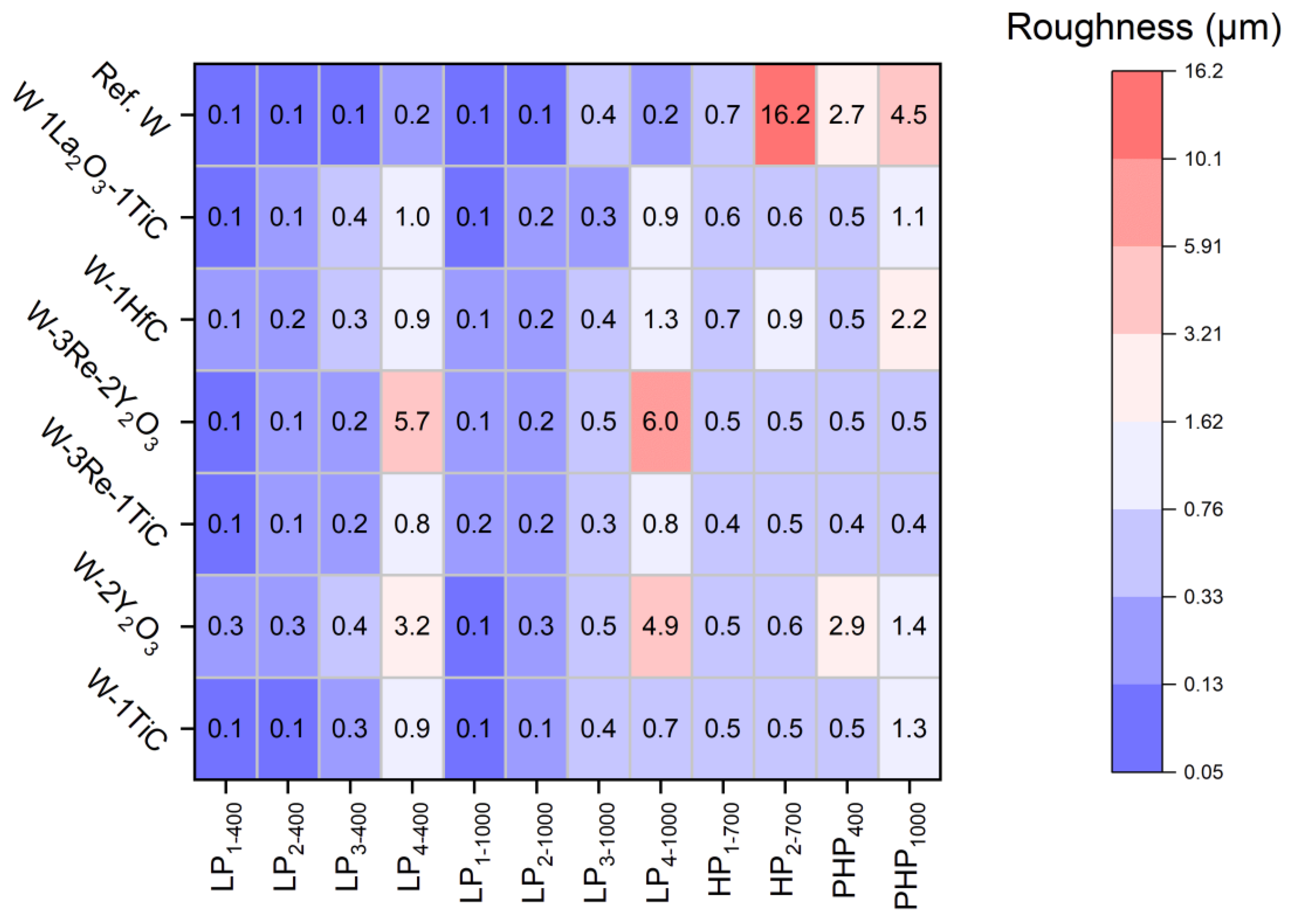
| Testing Condition | W-1TiC | W-2Y2O3 | W-3Re-1TiC | W-3Re-2Y2O3 | W-1HfC | W-1La2O3-1TiC | Ref. W |
|---|---|---|---|---|---|---|---|
| LP1-400 | 0.09 | 0.26 | 0.12 | 0.12 | 0.13 | 0.12 | 0.10 |
| LP2-400 | 0.11 | 0.28 | 0.13 | 0.13 | 0.15 | 0.14 | 0.09 |
| LP3-400 | 0.30 | 0.37 | 0.22 | 0.19 | 0.34 | 0.36 | 0.11 |
| LP4-400 | 0.89 | 3.17 | 0.81 | 5.67 | 0.87 | 0.96 | 0.18 |
| LP1-1000 | 0.10 | 0.07 | 0.19 | 0.13 | 0.14 | 0.12 | 0.10 |
| LP2-1000 | 0.14 | 0.25 | 0.20 | 0.18 | 0.19 | 0.16 | 0.11 |
| LP3-1000 | 0.38 | 0.52 | 0.33 | 0.47 | 0.43 | 0.31 | 0.39 |
| LP4-1000 | 0.74 | 4.91 | 0.81 | 5.99 | 1.31 | 0.86 | 0.24 |
| HP1-700 | 0.48 | 0.46 | 0.43 | 0.45 | 0.73 | 0.57 | 0.66 |
| HP2-700 | 0.49 | 0.56 | 0.45 | 0.51 | 0.91 | 0.59 | 16.2 |
| PHP400 | 0.45 | 2.88 | 0.44 | 0.48 | 0.50 | 0.45 | 2.70 |
| PHP1000 | 1.26 | 1.37 | 0.44 | 0.50 | 2.19 | 1.07 | 4.49 |
Disclaimer/Publisher’s Note: The statements, opinions and data contained in all publications are solely those of the individual author(s) and contributor(s) and not of MDPI and/or the editor(s). MDPI and/or the editor(s) disclaim responsibility for any injury to people or property resulting from any ideas, methods, instructions or products referred to in the content. |
© 2025 by the authors. Licensee MDPI, Basel, Switzerland. This article is an open access article distributed under the terms and conditions of the Creative Commons Attribution (CC BY) license (https://creativecommons.org/licenses/by/4.0/).
Share and Cite
Gago, M.; Antusch, S.; Klein, A.; Kreter, A.; Linsmeier, C.; Rieth, M.; Unterberg, B.; Wirtz, M. Thermal Shock and Synergistic Plasma and Heat Load Testing of Powder Injection Molding Tungsten-Based Alloys. J. Nucl. Eng. 2025, 6, 25. https://doi.org/10.3390/jne6030025
Gago M, Antusch S, Klein A, Kreter A, Linsmeier C, Rieth M, Unterberg B, Wirtz M. Thermal Shock and Synergistic Plasma and Heat Load Testing of Powder Injection Molding Tungsten-Based Alloys. Journal of Nuclear Engineering. 2025; 6(3):25. https://doi.org/10.3390/jne6030025
Chicago/Turabian StyleGago, Mauricio, Steffen Antusch, Alexander Klein, Arkadi Kreter, Christian Linsmeier, Michael Rieth, Bernhard Unterberg, and Marius Wirtz. 2025. "Thermal Shock and Synergistic Plasma and Heat Load Testing of Powder Injection Molding Tungsten-Based Alloys" Journal of Nuclear Engineering 6, no. 3: 25. https://doi.org/10.3390/jne6030025
APA StyleGago, M., Antusch, S., Klein, A., Kreter, A., Linsmeier, C., Rieth, M., Unterberg, B., & Wirtz, M. (2025). Thermal Shock and Synergistic Plasma and Heat Load Testing of Powder Injection Molding Tungsten-Based Alloys. Journal of Nuclear Engineering, 6(3), 25. https://doi.org/10.3390/jne6030025