Article

Two-Dimensional Fuel Assembly Study for a Supercritical Water-Cooled Small Modular Reactor

Dipartimento di Ingegneria Civile ed Industriale, Università di Pisa, Largo Lucio Lazzarino 2, I-56126 Pisa, Italy
J. Nucl. Eng. 2025, 6(3), 26; https://doi.org/10.3390/jne6030026
Submission received: 14 May 2025 / Revised: 28 June 2025 / Accepted: 3 July 2025 / Published: 9 July 2025

Abstract

Burnable poisoning and fuel enrichment zoning are two techniques often combined in order to optimize the fuel assembly behavior during the burnup cycle. In the present work, these two techniques will be applied to the 2D optimization of the fuel assembly conceptual design for the supercritical water-cooled reactor developed in the framework of the Joint European Canadian Chinese development of Small Modular Reactor Technology project, funded within the Euratom Research and Training programme 2019–2020. The initial configuration of the fuel assembly does not include any burnable absorbers and uses a homogeneous fuel enrichment of 7.5% in 235U. The infinite multiplication factor, k , starts from approximately 1.32 and drops, almost linearly, to 1.0 after a burnup of 40.0 MWd·kg−1. The uniform enrichment is, however, responsible for a pin-power peaking factor that with fresh fuel starts from 1.32 and reduces to 1.08 at the end of the burnup cycle. A simplified analytical model is developed to assess the effect of different lumped burnable absorbers on the time dependence of the assembly k . It is shown that using an adequate number of B4C rods, positioned in the outer wall of the fuel assembly, together with a suitable distribution of six different 235U enrichments, it allows for obtaining an assembly k factor that starts from 1.11 at the beginning of the cycle and remains quite constant over a large fraction of the burnup cycle. Moreover, the pin-power peaking factor is reduced to 1.03 at the beginning of the cycle and remains almost unchanged until the end of the burnup cycle.

1. Introduction

Nowadays, the energy industry is facing difficult challenges around the world as, on one hand, there is the necessity to reduce carbon emissions, and on the other, there is an always-growing demand for reliable and sustainable energy production. There is a growing consensus that nuclear energy will be an important player in this context, mainly due to its capacity to generate large amounts of low-carbon electricity [1].
Among the various nuclear technologies, Small Modular Reactors (SMRs) have the potential to mitigate issues commonly associated with more conventional nuclear power plants, such as high financial risks, long construction durations, and complex regulatory requirements. SMRs are designed to be compact and scalable for deployment in many different places, ranging from remote regions to urban areas. Such characteristics make SMRs a promising option for addressing a broad spectrum of energy demands, from the electricity supply to providing heat for industry or district heating, seawater desalination, and hydrogen production [2,3,4].
Many types of SMRs are currently under development; however, Supercritical Water Reactors (SCWRs), one of the six technologies identified and selected by the Generation IV International Forum [5], are unique for their distinctive benefits and innovative design [6,7]. SCWRs are operated at higher temperatures and pressures than traditional water-cooled reactors, using supercritical water both as coolant and working fluid. The superior thermodynamic properties of supercritical water make it possible to substantially improve the thermal efficiency of the nuclear reactor, leading to better fuel management and lower waste production. A conceptual study of a new type of Supercritical Water Small Modular Reactor (SCW-SMR) has been the object of the Joint European Canadian Chinese development of Small Modular Reactor Technology project (ECC-SMART), funded by the Euratom Research and Training programme 2019–2020 [8].
Careful use of nuclear fuel has always been one of the major concerns of the nuclear industry to obtain more efficient and longer-lasting nuclear reactors. Among the different solutions adopted to accomplish such a goal, the use of burnable absorbers (indeed, quite an old idea [9], and references therein) plays an important role. Burnable absorbers are materials deliberately introduced in the reactor core that absorb neutrons during the reactor operation and are transmuted into nuclides with generally a much lower absorption cross-section; in that sense, they are hence burnable. The disappearance of absorbing elements from the core is equivalent to a positive reactivity introduction, which counterbalances the natural reactivity reduction due to the fuel consumption. There are many advantages related to the use of burnable absorbers. They allow for an extension of the burnup of the fuel, a more uniform neutron flux distribution in the core, and a reduction in the operational burden on the reactor control system (due to the reduced reactivity inventory) [9,10]. Burnable absorbers can be integrated with the nuclear fuel (e.g., mixed, inserted, or as a coating) or loaded within the reactor core structures [11,12,13,14]. A comprehensive review of burnable absorbers is given in [14].
To ensure safety, nuclear reactors must be operated so that the peak local power does not exceed the maximum allowable value. If not properly controlled, inherent power distribution variations inside the reactor can hinder the efficient utilization of nuclear fuel. A high power peaking factor—defined as the ratio of the maximum power density to its average value—requires the reactor to operate at a lower power level to keep the hottest point within acceptable limits. For instance, a power peaking factor of 2.0 limits the reactor to 50% of the power achievable with a perfectly flat power distribution. Various techniques have been developed to flatten the power distribution and thus reduce the power peaking factor. Among them are fuel enrichment zoning, burnable poison-loaded fuel pins, and power-shaping control rods.
This study focuses on a 2D optimization of the current fuel assembly conceptual design for the SCW-SMR of the ECC-SMART project. In particular, various types of burnable absorbers, including erbium, boron-based compounds, and gadolinium, will be considered to reduce the reactivity inventory and then alleviate the necessary worth of the control rod system. Thus, to ensure a long-lasting effect, the study will prioritize lumped burnable absorbers rather than a homogeneous mixture within the fuel or other assembly components. Additionally, an appropriate fuel enrichment zoning strategy will be discussed to flatten the power distribution within the assembly and reduce the pin-power peaking factor throughout the entire burnup cycle.

2. The SCW-SMR Fuel Assembly

The fuel assembly reference layout of the supercritical water small modular reactor, studied in the framework of the ECC-SMART project, is shown in Figure 1. The fuel assembly is a 7 × 7 lattice with a pitch of 9.5 mm, containing 40 fuel rods with a radius of 3.45 mm. A previous work [15] has shown that a core based on UO2 with a uranium enrichment of 5.0% cannot achieve a refuelling/shuffling time of at least two years (one of the objectives of the ECC-SMART project). The same work has shown that such a length of the fuel cycle can instead be obtained, adopting a suitable distribution of assemblies characterized by three different average enrichments, namely 5.0%, 7.4%, and 10.0%. In view of that, the fuel of the reference assembly for the present study is UO2 with a 235U enrichment of 7.5% by weight, a density of 10.3 g·cm−3, and a temperature of 1054.2 K. As reported in [16], the reactor in this preliminary design has a power of 290 MW and operates at a core inlet pressure of 25 MPa. The reactor core is characterized by seven horizontal heat-up stages, necessary to reduce the peak coolant temperatures (a coolant mixing is foreseen at the end of each stage before entering the next one). The maximum linear heat rate is limited by the fuel and cladding peak temperatures, which should not exceed their respective maximum tolerable values. The maximum assembly average linear heat rate, in the first three heat-up stages, is equal to 7.2 kW·cm−1 and is taken as reference for the present study.
The fuel cladding is made of stainless steel 310S and has inner and outer radii of 3.5 and 4.0 mm, respectively. The fuel assembly is of closed type (BWR-like) with the moderator flowing both outside, through the 18 mm thick gap among them, and inside, within a central square water box. The wall of the fuel assembly has a sandwich-like structure that, starting from the outside, is made by a 2.5 mm thick layer of zircaloy-4, followed by a 4.0 mm thick layer of yttria (the insulator) and then by a 0.4 mm thick layer of stainless steel 310S. The central water box has the same sandwich-like structure as the assembly wall but in the opposite order, in such a way that the 310S stainless steel fully binds the coolant flowing inside the assembly. The thicknesses in the case of the water box are 0.4 mm, 2.0 mm, and 0.8 mm for the 310S, yttria, and zircaloy-4, respectively. The outer side of the assembly is 81.3 mm, while the outer side of the water box is 20.5 mm. The temperature and density of the coolant are 659.2 K and 0.330 g·cm−3, while they are 555.1 K and 0.775 g·cm−3 for the outside moderator and 572.3 K and 0.746 g·cm−3 for the inside moderator. The stainless steel 310S has the same temperature as the coolant, while the other materials are assumed to be at the same temperature as the moderators. The above values of densities and temperatures have been obtained by coupled simulations between the neutronic Monte Carlo code Serpent [17] and the thermal–hydraulic system code RELAP/SCDAPSIM [18] for the beginning of cycle conditions and kept constant during the depletion simulations described in the following.

3. Burnable Absorbers

3.1. Simplified Analytical Model

The model described hereafter does not aim to be rigorous but to provide a simple analytical tool to estimate the effect on the multiplication factor of different lumped burnable absorbers positioned inside a fuel assembly. Such a tool can help to circumscribe the set of successive Monte Carlo simulations necessary for a detailed analysis. Thus, some simplifications will be mandatorily introduced. In particular, the lumped absorber is assumed to have a cylindrical shape and be surrounded by a uniform moderator, large enough to be considered infinite. Similar treatment can be found in [14,19,20].
Inside a lumped thermal neutron absorber, the neutron flux is depressed so that the nuclides towards the center of the absorber are exposed to a lower neutron flux than those at its surface. A measure of such depression is represented by the self-shielding factor, defined as the ratio between the average thermal neutron flux in the absorber and the average thermal neutron flux that would be at the same place without it. The self-shielding factor, g t , depends on the time, since the absorption macroscopic cross-section changes with the absorber burnout, and thus, the flux depression inside of it changes too. In any approximation of the monokinetic Boltzmann transport equation, the self-shielding factor of a lumped absorber in a homogeneous medium can be represented by the following power series [9,21,22]:
g t = 1 + n = 1 a n 2 t d Σ a t n 1 1 + 2 a 1 t d Σ a t 1
where a n represents coefficients dependent on the composition and geometry of the medium around the absorber, t d is the absorber thickness (e.g., the radius in the case of a cylindrical rod) and Σ a t is the time-dependent macroscopic absorption cross-section of the absorber. As reported by [9], by increasing the index n, the coefficients a n rapidly vanish, thus justifying the approximation of the power series by its first term only.
The same form of the self-shielding factor is reported by [23]; here a factor C = 2 a 1 is introduced in the approximate form of Equation (1) and determined by fitting the calculated values of the self-shielding factor as a function of the optical thickness of the neutron absorber, τ p = t d Σ a t . Following that approach, simple depletion simulations were performed using the Monte Carlo code OpenMC [24] to estimate the self-shielding factors of absorbing rods with various radii. The model consisted of the rods surrounded by an infinite water moderator, in which neutrons were uniformly generated with a Maxwellian energy distribution determined by the medium temperature. The self-shielding factor is thus given by the ratio between the average neutron flux inside the absorbing rod and the moderator. Many strategies can be devised to calculate the a 1 constant; however, in the present work, it has been chosen to adhere to the theory for which the self-shielding is a function of the optical path rather than the different kinds of absorbers. Thus, it has been preferred to let all the absorbers concur on the definition of a single constant that could be applied without distinction to all of them. Fitting the OpenMC results, we get for the constant a 1 appearing in Equation (1) the value of 1.1345. Figure 2 shows the OpenMC self-shielding factors as a function of the absorber’s optical thickness and the fitting function (solid line) shaped according to Equation (1).
To account for the self-shielding phenomenon of an absorber, a time-dependent shielded macroscopic absorption cross-section can be used, Σ ^ a t , defined as
Σ ^ a t = g t Σ a t .
Let us start by considering two distinct thermal-neutron absorbers: the U-235 in the fuel and a burnable poison. In the following, the quantities referring to these two absorbers will be characterized by the indices 25 (i.e., the last digit of Z multiplied by 10, plus the last digit of A; a historical notation used to indicate fissile nuclides [25,26]) and P, respectively.
Let us start by considering two distinct thermal-neutron absorbers, the 235U in the fuel and a burnable absorber or poison. In the following, the quantities referring to these two absorbers will be characterized by the indices 25 (i.e., the last digit of Z multiplied by 10, plus the last digit of A; a historical notation used to indicate fissile and fissionable nuclides, see, e.g., [25,26]) and P, respectively.
The variation with time of the 235U atom density, N 25 t , is given by
d d t N 25 t = Σ ^ a 25 t ϕ t h F t = N 25 t g F t σ a 25 ϕ t h F t ,
with g F t and σ a 25 the time-dependent self-shielding factor of the fuel and the 235U microscopic absorption cross-section for thermal neutrons, respectively, while ϕ t h F t is the total thermal neutron flux inside the fuel.
The assumption of a constant reactor power provides the following relation:
N 25 0 g F 0 σ f 25 ϕ t h F 0 · E f = N 25 t g F t σ f 25 ϕ t h F t · E f ,
where σ f 25 is the thermal microscopic fission cross-section of the fuel and E f is the energy released per fission. Equation (4) allows obtaining the time-dependent neutron flux
ϕ t h F t = N 25 0 N 25 t g F 0 g F t ϕ t h F 0 ,
where N 25 0 and ϕ t h F 0 are, respectively, the initial ( t = 0 ) atom density of the fuel and neutron flux, both assumed as given.
The fuel self-shielding factor is supposed to depend only on the presence of 235U (as we will see shortly, this assumption is somehow relaxed because the self-shielding factor contributes to evaluating the 235U and poison concentrations only with its value at t = 0 , i.e., when no other strong absorbers are present in the fuel) and, according to Equation (1), is given by
g F t = 1 1 + γ F N 25 t ,
with
γ F = 2 a 1 r F σ a 25 ,
where r F is the radius of the fuel rod.
In turn, Equation (5) allows writing Equation (3) in the following form:
d d t N 25 t = N 25 0 g F 0 σ a 25 ϕ t h F 0 ,
which, once integrated, provides
N 25 t = N 25 0 1 β 25 t ,
where β 25 = g F 0 σ a 25 ϕ t h F 0 .
In analogy with Equation (3), the variation with time of the atom density of the burnable poison is given by
d d t N P t = Σ ^ a P t ϕ t h P t = N P t g P t σ a P ϕ t h F t ϕ ¯ t h P ϕ ¯ t h F .
In the above equation, g P t and σ a P are, respectively, the burnable absorber time-dependent self-shielding factor and microscopic absorption cross-section for thermal neutrons. The factors ϕ ¯ t h P and ϕ ¯ t h F are the average thermal flux at the place of the burnable absorber and the fuel. Thus, their ratio, assumed to be time-independent for simplicity, accounts for the different thermal neutron fluxes to which the burnable absorber and the fuel are exposed. According to Equation (1), the burnable poison self-shielding factor is given by
g P t = 1 1 + γ P N P t ,
with
γ P = 2 a 1 r P σ a P ,
where r P is the radius of the poison (here assumed to be, as for the fuel, in the shape of a cylindrical rod).
Equation (10), after introducing Equations (5), (6), (9) and (11), reduces to
d d t N P t = β P N P t 1 + γ P N P t γ F N 25 0 + 1 1 β 25 t ,
with β P = g F 0 σ a P ϕ t h F 0 · ϕ ¯ t h P / ϕ ¯ t h F , and it can be rearranged in the following form:
d d t ln N P t = γ P d d t N P t β P γ F N 25 0 + 1 1 β 25 t .
Integrating Equation (14), it follows that
ln N P t = γ P N P t β P γ F N 25 0 t + β P β 25 ln 1 β 25 t + C 0 .
The constant C 0 is determined by considering that for t = 0 , the atom density of the poison is given and equal to N P 0 . Thus, from Equation (15), it follows that
C 0 = ln N P 0 + γ P N P 0 .
Including Equation (16) into Equation (15), we get
ln N P t = ln N P 0 + γ P N P 0 γ P N P t β P γ F N 25 0 t + β P β 25 ln 1 β 25 t ,
from which it follows that
N P t = N P 0 e γ P N P t e γ P N P 0 β P γ F N 25 0 t 1 β 25 t β P β 25 ,
or, equivalently,
γ P N P t e γ P N P t = γ P N P 0 e γ P N P 0 β P γ F N 25 0 t 1 β 25 t β P β 25 .
The above equation has the form w e w = λ , and holds if and only if w = W 0 λ , with W 0 the principal branch of the Lambert W-function.
The time-dependent atom density of the burnable poison is finally given by
N P t = 1 γ P W 0 γ P N P 0 e γ P N P 0 e β P γ F N 25 0 t 1 β 25 t β P β 25 .
However, the neutron absorption by 238U produces 239Pu and, through successive further absorptions, 241Pu. Both are fissile nuclides and thus have an impact on the time behavior of the multiplication factor. Moreover, with the burnup, the fission reactions induce the appearance of new absorbing nuclides in the fuel, due to the accumulation of the fission products. To take into account these phenomena, while keeping the spirit of a simple analytical approach, the variation of the time-dependent 239Pu concentration, N 49 t (according to the notation introduced above), can be approximated as
d d t N 49 t = N 28 σ a 28 + ϵ 25 ν 25 N 25 t σ f 25 + ϵ 49 ν 49 N 49 t σ f 49 1 p p a 28 N 49 t σ a 49 · g F t ϕ t h F t
where, other than the parameters with obvious notation, p and p a 28 are, respectively, the probability for a neutron to survive the resonance absorption (i.e., the p of the four-factor formula) and the probability to be absorbed by 238U, during the slowing down. Moreover, the 238U density, N 28 , has been assumed to be constant with time.
Thanks to Equations (5), (6) and (9), and the initial condition that no 239Pu is present at t = 0 , the solution of Equation (21) is
N 49 t = b 0 σ a 25 + c 0 x 25 t c 0 σ a 25 x 25 t a 0 c 0 1 x 25 t c 0 σ a 25 ,
where
x 25 t = N 25 t N 25 0 ,
a 0 = N 28 σ a 28 ,
b 0 = ϵ 25 ν 25 N 25 0 σ f 25 1 p p a 28 ,
c 0 = ϵ 49 ν 49 σ f 49 1 p p a 28 σ a 49 .
The variations with time of the 240Pu and 241Pu atom densities, N 40 t and N 41 t , respectively, are approximated by the two following differential equations:
d d t N 40 t = N 49 t σ c 49 g F t + σ c , f n 49 χ r ϕ t h F t N 40 t σ a 40 g F t + σ a , f n 40 χ r ϕ t h F t ,
d d t N 41 t = N 40 t σ c 40 g F t + σ c , f n 40 χ r ϕ t h F t N 41 t σ a 41 g F t + σ a , f n 41 χ r ϕ t h F t ,
where σ c , f n and σ a , f n are, respectively, the fast capture and absorption microscopic cross-sections, and χ r is instead the fast-to-thermal flux ratio, which, for the sake of simplicity, is assumed to be time-independent. As before, solving Equations (26) and (27) with the initial condition N 40 0 = N 41 0 = 0 , we get
N 40 t = m 1 x 25 t e 1 m 2 x 25 t m 3 + m 2 + m 3 m 1 x 25 t e 2 ,
N 41 t = σ c 40 + σ c , f n 40 χ r n 1 x 25 t e 1 n 2 x 25 t n 3 x 25 t e 2 n 4 x 25 t e 2 + n 5 x 25 t e 3 ,
where
e 1 = c 0 σ a 25 ,
e 2 = σ a 40 + σ a , f n 40 χ r σ a 25 ,
e 3 = σ a 41 + σ a , f n 41 χ r σ a 25 ,
m 1 = σ c 49 + σ c , f n 49 χ r σ a 40 + σ a , f n 40 χ r + c 0 ,
m 2 = b 0 σ c 49 + σ c , f n 49 χ r σ a 25 + c 0 σ a 40 + σ a , f n 40 χ r σ a 25 ,
m 3 = a 0 σ c 49 + σ c , f n 49 χ r c 0 σ a 40 + σ a , f n 40 χ r ,
n 1 = m 1 σ a 41 + σ a , f n 41 χ r + c 0 ,
n 2 = m 2 σ a 41 + σ a , f n 41 χ r σ a 25 ,
n 3 = m 3 σ a 41 + σ a , f n 41 χ r ,
n 4 = m 1 m 2 m 3 σ a 41 + σ a , f n 41 χ r σ a 40 + σ a , f n 40 χ r ,
n 5 = n 4 n 1 + n 2 + n 3 .
To take into account the accumulation of the fission products, we can instead use the following equation:
d d t N f p t = 2 N 25 t g F t σ f 25 ϕ t h F t + 2 N 49 t g F t σ f 49 ϕ t h F t N f p t g F t σ a f p ϕ t h F t ,
where N f p t and σ a f p are the atom density and the thermal-averaged thermal absorption cross-section of the fission products, respectively.
Taking advantage of Equations (5), (6), (9) and (22), imposing that N f p 0 = 0 , it follows that
N f p t = u 1 x 25 t + u 2 x 25 t e 1 u 3 + u 4 x 25 t e 4 ,
where
e 4 = σ a f p σ a 25 ,
u 1 = 1 σ a 25 σ a f p N 25 0 σ f 25 b 0 σ f 49 σ a 25 + c 0 ,
u 2 = 1 σ a f p + c 0 b 0 σ a 25 + c 0 + a 0 c 0 σ f 49 ,
u 3 = a 0 c 0 σ f 49 σ a f p ,
u 4 = u 1 u 2 + u 3 ,
with e 1 , a 0 , b 0 and c 0 as by Equations (30), (23), (24) and (25), respectively.
To assess the influence on the multiplication factor of the variation with time of fuel and poison atom densities, let us consider a homogenized fuel assembly with full reflective boundary conditions (i.e., an infinite lattice of identical fuel assemblies).
The time-dependent infinite multiplication factor, k , is given by the well-known four-factor formula
k t = ϵ p f t η t = ϵ p ν Σ ˜ f t Σ ˜ a t ,
where Σ ˜ f t and Σ ˜ a t are the time-dependent, thermal-averaged, and homogenized fission and absorption cross-sections (for the sake of simplicity, it is assumed that the fast fission factor, ϵ , and the resonance absorption escape probability, p, are both time-independent). In the case of a reactor without burnable absorbers, it is
Σ ˜ a t = Σ ^ a F t V F V ϕ ¯ t h F ϕ ¯ t h + Σ ^ a N F ,
where the first term on the r.h.s., Σ ^ a F t , is the time-dependent shielded macroscopic absorption cross-section of the fuel, weighted by both volumes ( V F is the volume of the fuel and V the volume of the assembly) and fluxes ( ϕ ¯ t h F and ϕ ¯ t h are the average thermal neutron flux in the fuel and the assembly, respectively), and Σ ^ a N F is, instead, the sum of the homogenized macroscopic cross-sections of all the other components of the system, similarly weighted and assumed to be time-independent. By incidence, we can observe how the fuel self-shielding factor, given by Equation (6), can now be evaluated considering not only the 235U but also all the other nuclides that appear in the fuel during the burnup.
When a burnable poison is added to the system, the homogenized macroscopic absorption cross-section in Equation (48) takes instead the following form:
Σ ˜ a t = Σ ^ a F t V F V ϕ ¯ t h F ϕ ¯ t h + Σ ^ a P t V P V ϕ ¯ t h P ϕ ¯ t h + Σ ^ a N F ,
where the second term on the r.h.s. is the time-dependent shielded macroscopic absorption cross-section of the poison weighted by volumes and fluxes as discussed above.
Introducing Equation (49) or (50) into Equation (48) allows estimating the evolution with time of the multiplication factor for the case without or with the presence of the burnable absorber, respectively.
Given the assembly geometry and composition, a single dedicated Monte Carlo simulation, without any burnable absorber, allows obtaining all the parameters necessary to apply this model and thus to start a preliminary analysis of the behavior of different kinds and amounts of burnable absorbers. Moreover, such a simulation can estimate the contribution of the saturated concentration of 135Xe and 149Sm to the fuel macroscopic absorption cross-section in Equations (49) and (50).

3.2. Burnable Absorbers for the SCW-SMR Fuel Assembly—Analytical Study

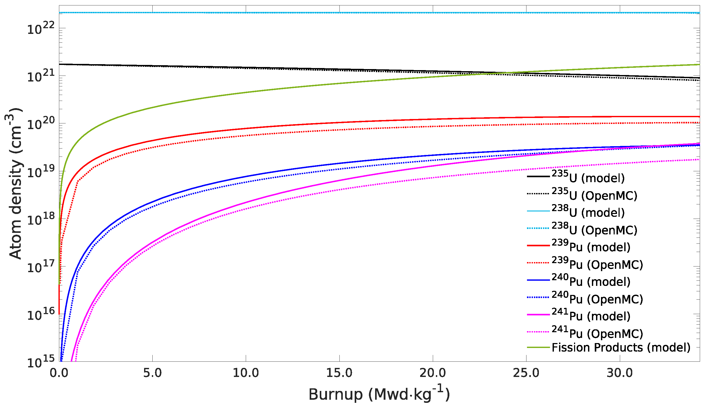
To validate the simplified analytical model described in the previous section, the variation of nuclide densities with burnup was estimated using Monte Carlo simulations. Since OpenMC does not provide a standard deviation for the estimated nuclide densities, five depletion simulations of the SCW-SMR fuel assembly (see Section 2) were performed, each using a different seed for the random number generator. From these runs, the average density and the corresponding relative standard deviation for each nuclide were calculated at each timestep. The largest relative standard deviation was 0.65% for the Pu-241 density at the end of the fifth timestep. As shown by Figure 3, the results provided by the model are quite in agreement with those given by the much more accurate Monte Carlo simulation. The model shows a slight overestimation, at any burnup, of the concentrations of 239Pu and 240Pu, while for 241Pu there is an overestimation that starting from a burnup of 5 MWd·kg−1 increases with it. Computing time is of the order of a few seconds for the analytical model with respect to the 1200 s used by OpenMC.
In the following sections, three different burnable poisons, characterized by an absorption cross-section similar, larger, and much larger than that of the fuel, will be considered to study the evolution of the assembly infinite multiplication factor k (see Equation (48)), as a function of the fuel burnup. Moreover, in order to define the ratio ϕ ¯ t h P / ϕ ¯ t h F , which appears in the parameter β P of Equation (20), the lumped burnable absorbers are supposed to be positioned inside the yttria insulator of the assembly wall (see again Figure 1).

3.2.1. Erbium

Let us assume that the assembly of Figure 1 contains some cylindrical rods made of erbium (with natural isotopic composition) in the yttria region of the outer assembly wall. Taking the initial total mass of Er equal to a specific fraction of the total fuel mass, increasing the number of Er rods requires a reduction in their radius, thus allowing consideration for a lower self-shielding.
Figure 4 shows the variation of the assembly infinite multiplication factor as a function of the fuel burnup, for different radii of the absorbing rods and two values of the Er initial total mass, namely 1.5% and 2.5% of the fuel mass. As expected, the burnable absorber reduces the initial inventory of reactivity. Increasing the burnup, and then the consumption of fuel and absorber, the assembly reactivity shows first a small increment before decreasing with a rate lower than in the case without the absorber. Nonetheless, it appears impossible to completely burn the Er poison, as in all the cases the multiplication factor falls below 1.0 before the burnup of 40.2 MWd·kg−1, achievable without the addition of the burnable absorber. This behavior is due to the comparable absorption cross-section of 167Er and 235U, which makes their burning rate similar. As pointed out in [27], a relevant characteristic of Er is that its addition enhances the negativity of the fuel temperature coefficient, thanks to the large resonance lying at the upper edge of the thermal energy range; see Figure 5.

3.2.2. Boron Carbide

The second burnable absorber considered is boron carbide, B4C, with boron natural isotopic composition. As for the case of erbium, with a fixed total initial mass of the absorber, increasing the number of burnable rods allows considering lumped absorbers with reduced radius and hence lowering self-shielding.
Figure 6 shows the variation of the multiplication factor as a function of the fuel burnup for different radii of the absorber rods, starting with an initial total mass of B4C equal to 0.15% and 0.20% of that of the fuel. Using B4C introduces a reactivity swing, visible with almost any considered radius of the rods. According to the simplified analytical model, the radius that shows the smaller reactivity variation, up to a burnup value of 25–30 MWd·kg−1, should approximately be in the range between 0.3 and 0.4 mm. Since the absorption cross-section of 10B is sensibly greater than that of the fuel, it appears that, for all the presented cases (if an exception is made for the larger radius with the higher amount of B4C), the burnable absorber is fully consumed, as the reactivity, above a certain burnup, approaches and follows the curve of the case of no poison.

3.2.3. Gadolinium

The last burnable absorber of this analysis is gadolinium, Gd, also in this case with natural isotopic composition. Gd has two isotopes with high absorption cross-section for thermal neutrons, namely 155Gd and 157Gd. However, since the developed analytical model derived here allows considering a single absorbing nuclide, an average thermal absorption cross-section has been defined by weighting those of 155Gd and 157Gd on their respective atom densities. The result is a Gd burnable absorber characterized by a Maxwellian-averaged microscopic absorption cross-section of 60606 b and an atom density of 9.21 × 10 21 cm−3.
The change of the assembly multiplication factor as a function of the fuel burnup, for different radii of the Gd rods, is shown in Figure 7, considering a total initial mass of the absorber equal to 0.1% and 0.5% of the total mass of the fuel. Due to its large absorption cross-section, the burnout rate of the Gd is much faster than that of the fuel. According to Figure 7, the Gd rods will be entirely burned before a burnup of 8.0 and 17.0 MWd·kg−1, for the two fractions of absorber considered; the multiplication factor, in all the cases, soon approaches and follows the no-poison curve. Due to such a high consumption rate, if Gd is not lumped into relatively thick rods, it seems more appropriate to control reactivity variations on a short time scale, like those induced by the accumulation of saturable fission products, which naturally follows the startup of the reactor or the burning of a fresh fuel assembly.

3.3. Burnable Absorbers for the SCW-SMR Fuel Assembly—Monte Carlo Study

All the simulations of the present section have been performed on a Cluster of the University of Pisa Green Data Center using 9 or 12 nodes with 18 and 22 CPUs each, respectively, installing OpenMC in a Debian 12-based Singularity container integrated with the PBS job scheduler.
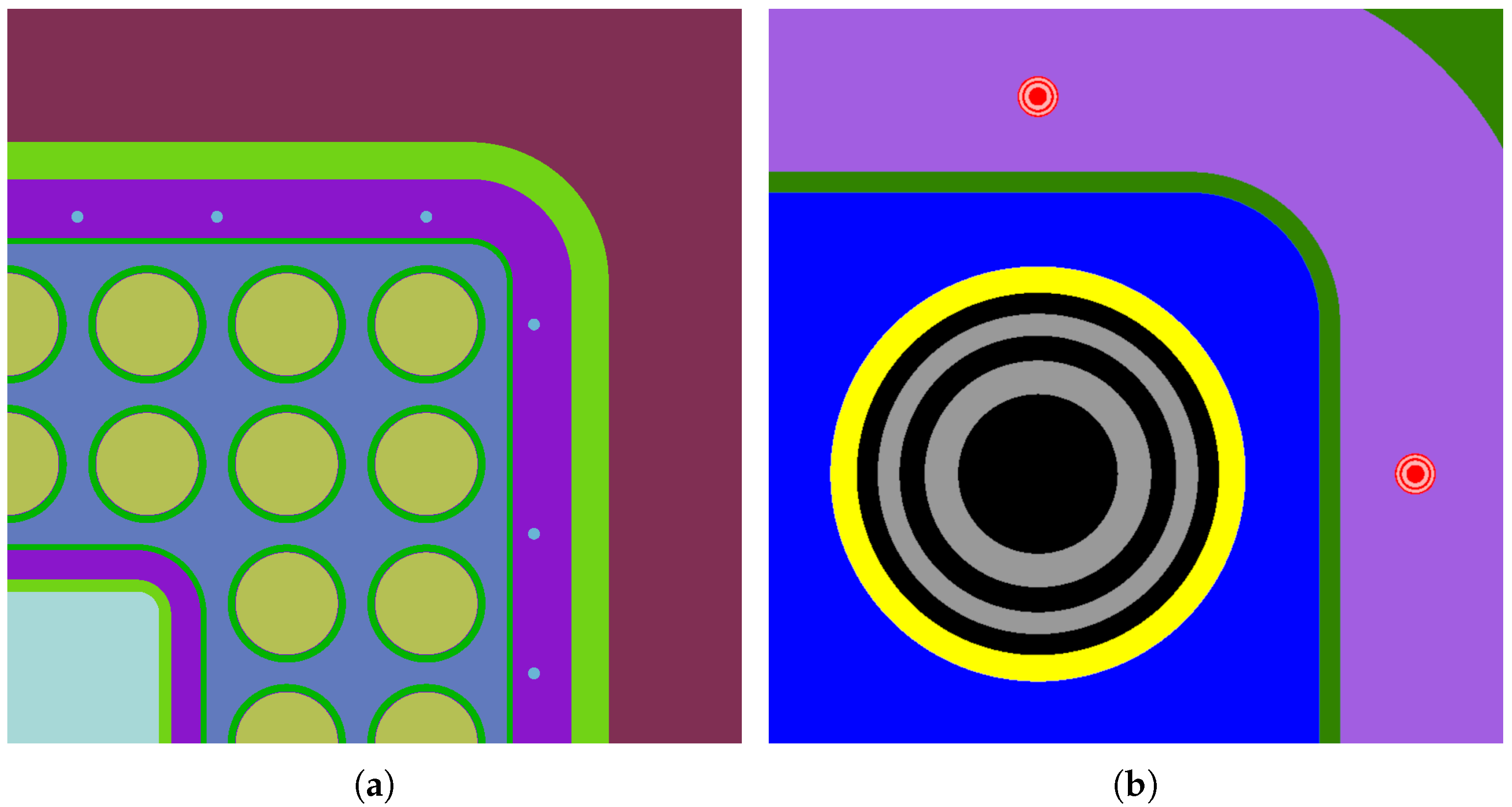
According to the results of the analytical study shown in the previous section, simulations with the OpenMC Monte Carlo code of the SCW-SMR fuel assembly have been performed considering 24 rods of burnable absorbers placed within the yttria insulator of the assembly outer wall, as shown in Figure 8a. Moreover, to account for the self-shielding effect and allow for a non-uniform consumption, the fuel and burnable absorbers have been subdivided into five regions with the same volume, as shown in Figure 8b. All the depletion simulations have been performed using, for each timesteps, 50 batches, 5 of which are inactive, of 10 5 neutrons each (enough to have a maximum error on the multiplication factor lower than 60 pcm for all the burnup steps). In particular, the neutrons of the first batch have been generated sampling their position uniformly within the volume of the fuel rods and their energy according to the Watt fission energy spectrum. The number of burnup time steps and their main characteristics are summarized in Table 1.
As previously stated, according to the analytical model of Section 3.1, the maximum burnup for the SCW-SMR fuel assembly, without burnable absorbers, is equal to 40.9 MWd·kg−1, a value that differs only by 2.2% (i.e., ≈19.3 days) with respect to the 40.0 MWd·kg−1 obtained with OpenMC.

3.3.1. Erbium

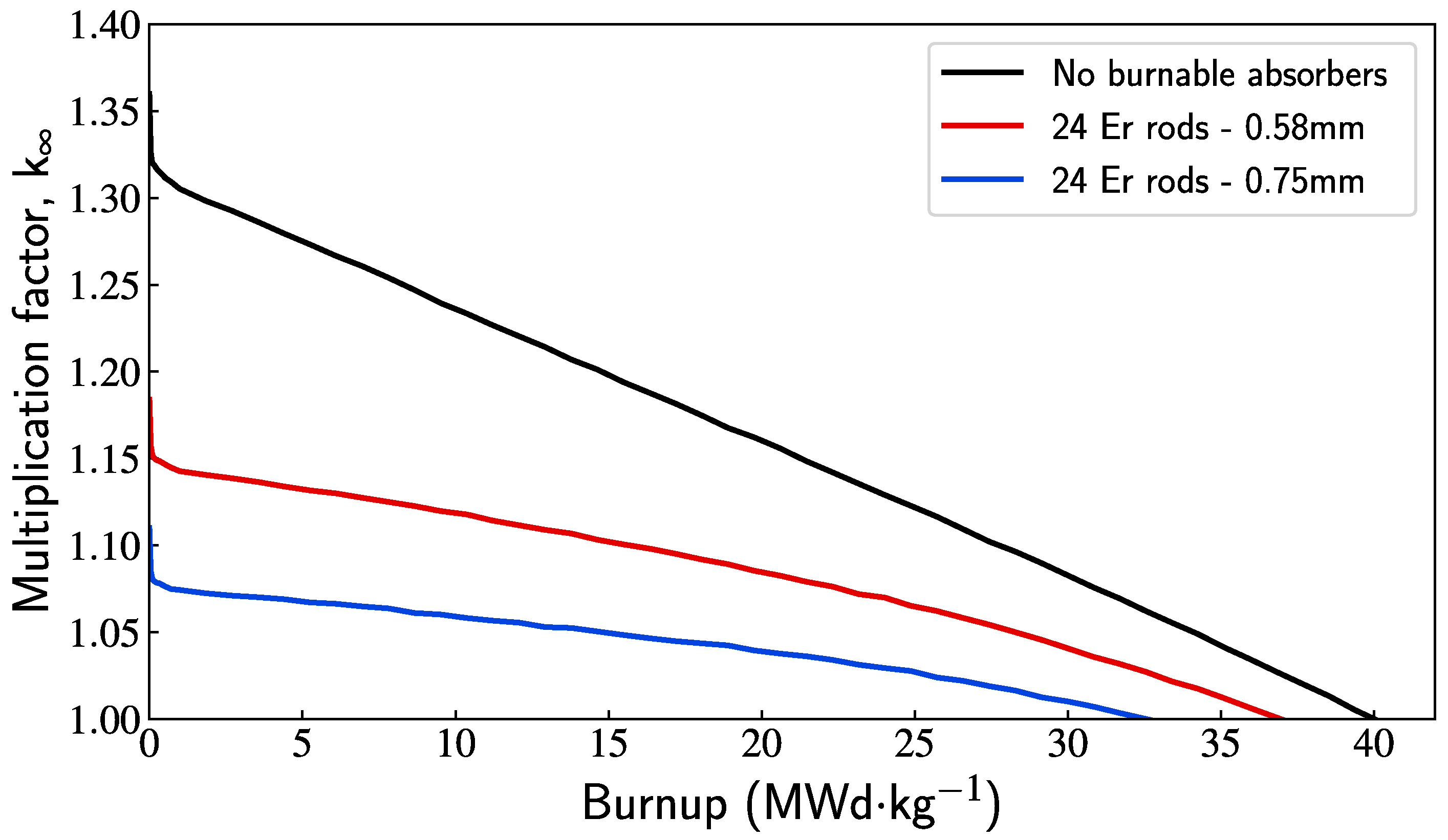
The effect of 24 rods of Er (natural isotopic composition) with radius of 0.58 or 0.75 mm on the multiplication factor as a function of the fuel burnup is shown in Figure 9. Both cases exhibit similar behavior to those shown in Figure 4. The maximum burnup values given by the analytical model in Section 3.1 are 39.0 and 37.2 MWd·kg−1 for the smaller and larger rod radii considered here. These two values differ from those obtained by OpenMC, which are 37.0 and 32.6 MWd·kg−1, by 5.4% and 14.1%, respectively. Monte Carlo simulations confirm the challenge of completely burning the Er rods, as the multiplication factor curves, in both scenarios, always fall below 1.0 before that of no burnable absorbers.

3.3.2. Boron Carbide

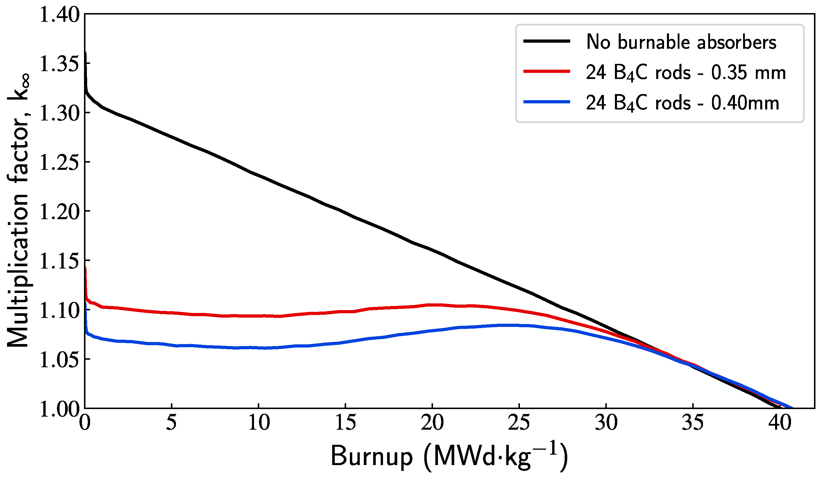
Figure 10 shows the expected behavior of the multiplication factor when the 24 rods are made of B4C (with B natural isotopic composition), and have a radius of 0.35 and 0.40 mm. As predicted also by the analytical model (see Figure 6), the multiplication factor shows a swing, although from the Monte Carlo simulations it appears slightly less pronounced. Additionally, thanks to the large absorption cross-section of 10B, the burnable absorber is entirely consumed and there is no reduction in the maximum achievable burnup. Rather, the maximum burnup seems slightly increased, as a consequence of a small pin-power flattening action exerted by the 24 B4C rods (although we can argue about the statistical significance of such a difference). The initial excess reactivity is remarkably reduced and the multiplication factor, in the case of 0.35 mm radius, remains quite constant up to a burnup of about 25.0 MWd·kg−1, thus allowing us to substantially reduce the movements of the reactor control rod system.

3.3.3. Gadolinium

As the last example, let us assume 24 rods with a 0.16 or 0.36 mm radius made of Gd with natural isotopic composition. Among the materials considered, Gd is the one with the highest absorption cross-sections. Having two absorbing nuclides, 155Gd and 157Gd, it required a special treatment in order to be considered by the analytical model of Section 3.1 (see also Section 3.2.3). Thus, as shown in Figure 11, it is not surprising that the agreement with the Monte Carlo simulations is, in this case, not as good. As already found in Section 3.2.3, although the Monte Carlo simulations show a flatter initial distribution with respect to the analytical results, the effect of the burnable absorbers is now limited to a shorter interval of burnup (or, equivalently, time), as both multiplication factor curves soon align and then follow that of no burnable absorbers.

4. Assembly Pin-Power Peaking Factor

The results of the previous section suggest that using 24 B4C rods with a radius of 0.35 mm inside the yttria insulator of the outer assembly wall allows obtaining an assembly infinite multiplication factor that remains quite constant over a large range of burnup (see Figure 10). Such an assembly configuration will now be adopted to start optimizing the pin power distribution through a suitable fuel enrichment zoning, aiming to obtain a pin-power peaking factor that remains limited (i.e., as close as possible to unity) for the whole length of the burnup cycle. The fuel assembly configured in this way, with a homogeneous enrichment in 235U equal to 7.5%, has a pin-power distribution as shown in Figure 12, where, in correspondence with each pin position, the ratio is reported between the pin power and the average value over all the assembly pins. Accordingly, the maximum value corresponds to the pin-power peaking factor, and for fresh fuel is equal to 1.32. However, increasing the fuel burnup, the power distribution naturally tends to flatten and the pin-power peaking factor reduces to 1.23 at 20.0 MWd·kg−1 and, finally, to 1.08 at the end of the fuel cycle (40.0 MWd·kg−1). Nevertheless, for a large fraction of the cycle, the pin-power peaking factor remains quite high, thus preventing efficient use of the fuel.
To flatten the assembly power profile from the beginning of the fuel burnup, we can differentiate the fuel enrichment, increasing its value in the positions where the pin power is lower than the average assembly value, and decreasing it vice versa. Such an enrichment zoning study has been performed with the constraints of keeping the average assembly enrichment as close as possible to 7.5% and limiting the maximum number of different fuel enrichments to an acceptable level. Good results have finally been achieved using six different enrichments. Although six may be close to the upper end of the acceptable number of enrichments, we note that this value is, however, coherent with the enrichment groups considered in the INEEL report of 2005 [28]. Figure 13 shows the fuel enrichment distribution obtained at the end of this study. The 235U enrichment ranges from 5.3% to 8.7% with an average value of 7.52%.
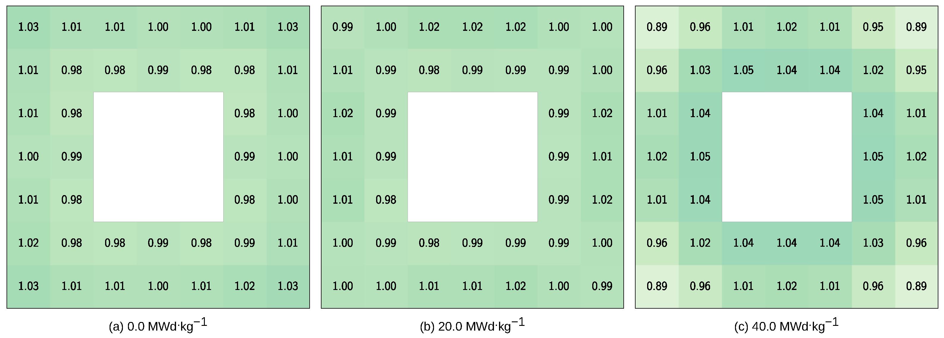
Figure 14 shows the pin-power distribution obtained with the new enrichments for the same three levels of burnup already considered in Figure 12. The pin-power peaking factor for fresh fuel is now substantially lower and equal to 1.03; it becomes 1.02 for a burnup of 20.0 MWd·kg−1 and reaches 1.05 for the final burnup of 40.0 MWd·kg−1.
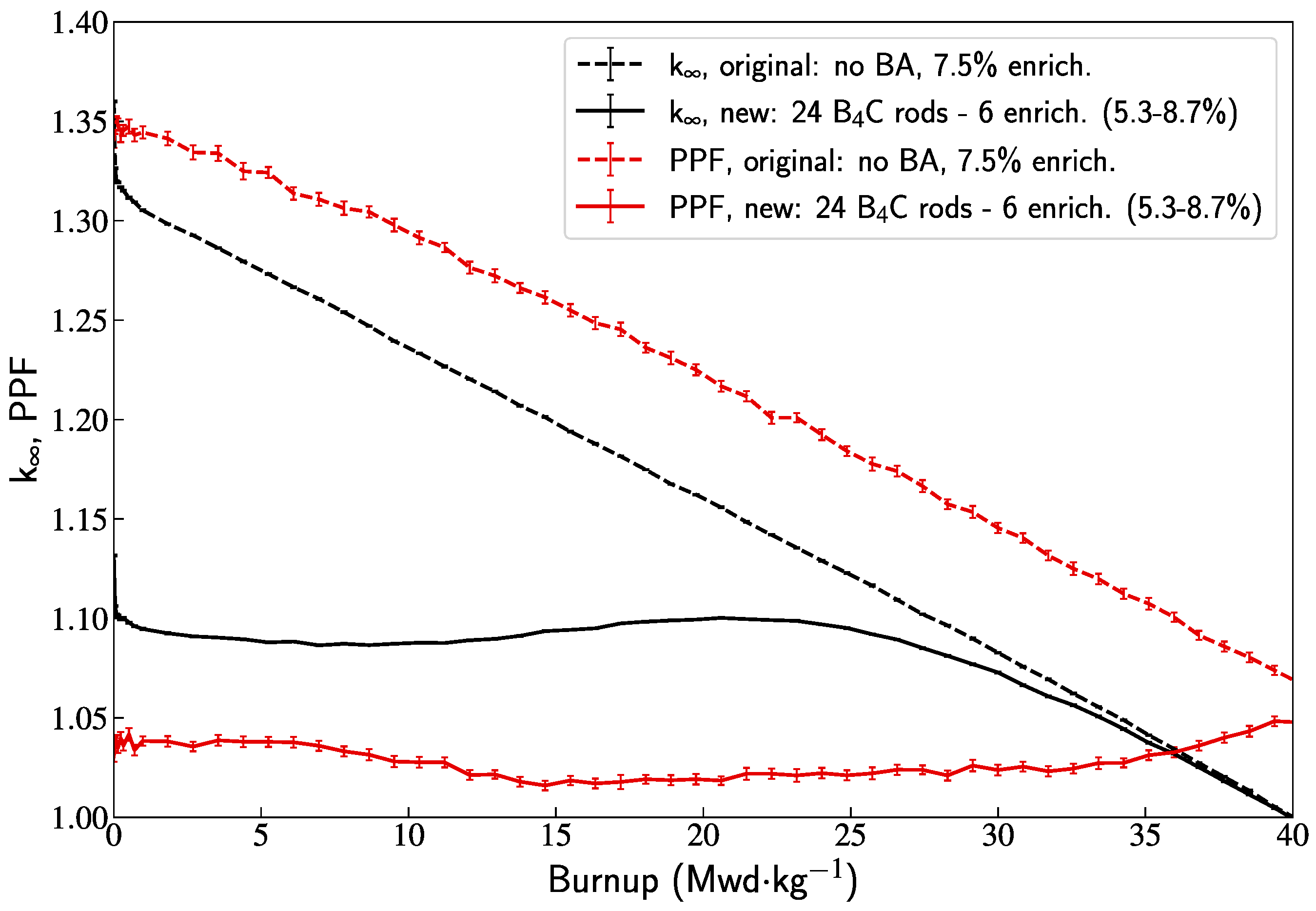
Finally, to summarize the improvement in the performance of the ECC-SMART fuel assembly, Figure 15 shows both the reactivity inventory and the pin-power peaking factor as a function of the burnup for the original and new assembly layout. It is clear that the latter, although somehow limited by being obtained with a 2D-only analysis, allows for much more efficient use of the fuel and a much easier reactor operation during the fuel cycle.

5. Conclusions

The ECC-SMART project, funded in the framework of the Euratom Research and Training programme 2019–2020, aimed at the conceptual study of a small-modular supercritical water-cooled reactor. The chosen reference layout of the fuel assembly is similar to that of a typical BWR and contains 40 fuel rods with uniform 235U enrichment, originally assumed to be equal to 5.0%. However, a previous study has shown that with such an enrichment, it is not possible to fulfill the requirement of a fuel cycle at least two years long. Thus, for the present study, the starting homogeneous enrichment of the assembly has been increased to 7.5%. This work aimed to identify possible strategies at the assembly level to reduce the reactivity inventory and homogenize the power distribution of the fuel pins. To accomplish that, the use of burnable absorbers and an appropriate enrichment zoning was investigated. A simplified analytical model has been derived to quickly estimate the effect of different lumped burnable absorbers placed inside the fuel assembly. To confirm the analytical results, Monte Carlo simulations with the OpenMC code were performed on a few selected cases. The use of 24 B4C rods with a radius of only 0.35 mm, almost uniformly distributed inside the outer yttria insulator, has shown to be effective in order to reduce the multiplication factor, k , from the value of 1.32, with no absorbers, to the value of 1.11, and to keep it quite constant up to a burnup of about 25.0 MWd·kg−1. Although a uniform enrichment of 7.5% would allow for an assembly burnup cycle as long as 885.0 days, the pin-power distribution is quite uneven and produces a pin-power peaking factor of 1.32 at the beginning of the cycle. Despite the natural flattening of the assembly power distribution with the fuel burnup, the pin-power peaking factor remains too high for a large fraction of the fuel cycle. Adopting six different enrichments ranging from 5.3% to 8.7% while keeping the assembly average value to 7.5%, the pin-power peaking factor at the beginning of the cycle can be drastically reduced to a value as low as 1.03, and kept almost constant through the entire burnup cycle.
Although the present work shows promising results, they need to be confirmed by full core simulations where the B4C burnable absorber rods and the enrichment zoning are applied to all the reactor’s assemblies. Such a study is ongoing, and the results will be presented in a future publication.

Funding

This research was conducted in the framework of the project “Joint European Canadian Chinese Development of Small Modular Reactor Technology (ECC-SMART)”, funded by the Euratom Research and Training programme 2019–2020 grant number 945234.

Data Availability Statement

The original contributions presented in this study are included in the article. Further inquiries can be directed to the corresponding author.

Conflicts of Interest

The author declares no conflicts of interest.

References

  1. Brook, B.W.; Alonso, A.; Meneley, D.A.; Misak, J.; Blees, T.; van Erp, J.B. Why nuclear energy is sustainable and has to be part of the energy mix. Sustain. Mater. Technol. 2014, 1–2, 8–16. [Google Scholar] [CrossRef]
  2. IAEA. Deployment Indicators for Small Modular Reactors; Number 1854 in Tecdoc Series; International Atomic Energy Agency: Vienna, Austria, 2018. [Google Scholar]
  3. IAEA. Small Modular Reactors: A New Nuclear Energy Paradigm; International Atomic Energy Agency: Vienna, Austria, 2022; Available online: https://smr.iaea.org (accessed on 4 July 2025).
  4. Lee, J.I. Review of Small Modular Reactors: Challenges in Safety and Economy to Success. Korean J. Chem. Eng. 2024, 41, 2761–2780. [Google Scholar] [CrossRef]
  5. Pioro, I.L.; Rodriguez, G.H. Chapter 2—Generation IV International Forum (GIF). In Handbook of Generation IV Nuclear Reactors, 2nd ed.; Pioro, I.L., Ed.; Woodhead Publishing Series in Energy; Woodhead Publishing: Cambridge, UK, 2023; pp. 111–132. [Google Scholar] [CrossRef]
  6. Starflinger, J.; Schulenberg, T. (Eds.) High Performance Light Water Reactor: Design and Analyses; KIT Scientific Publishing: Karlsruhe, Germany, 2012; p. 255. [Google Scholar] [CrossRef]
  7. Oka, Y.; Mori, H. Supercritical-Pressure Light Water Cooled Reactors; Springer: Tokyo, Japan, 2014. [Google Scholar] [CrossRef]
  8. Kryková, M.; Schulenberg, T.; Arnoult Růžičková, M.; Sáez-Maderuelo, A.; Otic, I.; Czifrus, S.; Cizelj, L.; Pavel, G.L. European Research Program on Supercritical Water-Cooled Reactor. J. Nucl. Eng. Radiat. Sci. 2020, 7, 021301. [Google Scholar] [CrossRef]
  9. Radkowsky, A. Theory and application of burnable poisons. In Proceedings of the 2nd United Nations International Conference on the Peaceful Uses of Atomic Energy, Geneva, Switzerland, 1–13 September 1958; Volume 13: Reactor Physics and Economics, pp. 426–445. [Google Scholar]
  10. Ohki, S. Fuel Burnup and Reactivity Control. In Nuclear Reactor Design; Oka, Y., Ed.; Springer: Tokyo, Japan, 2014; pp. 1–47. [Google Scholar] [CrossRef]
  11. Franceschini, F.; Petrović, B. Fuel with advanced burnable absorbers design for the IRIS reactor core: Combined Erbia and IFBA. Ann. Nucl. Energy 2009, 36, 1201–1207. [Google Scholar] [CrossRef]
  12. Choe, J.; Shin, H.C.; Lee, D. New burnable absorber for long-cycle low boron operation of PWRs. Ann. Nucl. Energy 2016, 88, 272–279. [Google Scholar] [CrossRef]
  13. Jo, Y.; Shin, H.C. Design optimization of cylindrical burnable absorber inserted into annular fuel pellets for soluble-boron-free SMR. Nucl. Eng. Technol. 2022, 54, 1464–1470. [Google Scholar] [CrossRef]
  14. Evans, J.A.; DeHart, M.D.; Weaver, K.D.; Keiser, D.D. Burnable absorbers in nuclear reactors—A review. Nucl. Eng. Des. 2022, 391, 111726. [Google Scholar] [CrossRef]
  15. Antók, C.; Czifrus, S.; Giusti, V. Neutronic calculations for preliminary core design of SCW-SMR. Ann. Nucl. Energy 2024, 209, 110805. [Google Scholar] [CrossRef]
  16. Schulenberg, T.; Otic, I. Suggestion for design of a small modular SCWR. In Proceedings of the 10th International Symposium on Supercritical WaterCooled Reactors (ISSCWR10), Prague, Czech Republic, 15–19 March 2021. Paper Number ISSCWR10-019. [Google Scholar]
  17. Leppänen, J.; Pusa, M.; Viitanen, T.; Valtavirta, V.; Kaltiaisenaho, T. The Serpent Monte Carlo code: Status, development and applications in 2013. Ann. Nucl. Energy 2015, 82, 142–150. [Google Scholar] [CrossRef]
  18. Allison, C.M.; Hohorst, J.K. Role of RELAP/SCDAPSIM in Nuclear Safety. Sci. Technol. Nucl. Install. 2010, 2010, 425658. [Google Scholar] [CrossRef]
  19. Meghreblian, R.; Holmes, D. Reactor Analysis; McGraw-Hill Series in Nuclear Engineering; McGraw-Hill: New York, NY, USA, 1960. [Google Scholar]
  20. Volkov, V.S.; Luk’yanov, A.S.; Chapkunov, V.V.; Shevyakov, V.P.; Yamnikov, V.S. Use of burnable poisons in nuclear reactors. Sov. J. At. Energy 1962, 11, 745–757. [Google Scholar] [CrossRef]
  21. Hurwitz, H.; Zweifel, P.F. Self-Shielding of Lumped-Poison Mixtures. Nucl. Sci. Eng. 1956, 1, 438–440. [Google Scholar] [CrossRef]
  22. Leonard, J.H.; Wackman, W. Lumped burnable poisons III—Applications. Trans. Am. Nucl. Soc. 1958, 1, 132–134. [Google Scholar]
  23. Yamashita, K. Optimization Method of Rod-Type Burnable Poisons for Nuclear Designs of HTGRs. J. Nucl. Sci. Technol. 1994, 31, 979–985. [Google Scholar] [CrossRef]
  24. Romano, P.K.; Horelik, N.E.; Herman, B.R.; Nelson, A.G.; Forget, B.; Smith, K. OpenMC: A state-of-the-art Monte Carlo code for research and development. Ann. Nucl. Energy 2015, 82, 90–97. [Google Scholar] [CrossRef]
  25. Zweifel, P. Reactor Physics; McGraw-Hill: New York, NY, USA, 1973. [Google Scholar]
  26. Henry, A. Nuclear-Reactor Analysis; MIT Press: Cambridge, MA, USA, 1975. [Google Scholar]
  27. Radkowsky, A.; Creagan, R.J. Poison control of thermal reactor. In Proceedings of the 3rd International Conference on the Peaceful Uses of Atomic Energy, Geneva, Switzerland, 31 August–9 September 1964; Volume 4: Reactor Control, pp. 277–284. [Google Scholar]
  28. McDonald, P.; Buongiorno, J.; Sterbentz, J.W.; Davis, C.; Witt, R. Feasibility Study of Supercritical Light Water Cooled Reactors for Electric Power Production. Nuclear Energy Research Initiative Project 2001-001, Westinghouse Electric Co. Grant Number: DE-FG07-02SF22533, Final Report. Available online: https://doi.org/10.2172/911007 (accessed on 4 July 2025).
Figure 1. Horizontal cut of the fuel assembly of the SCW-SMR currently under study in the ECC-SMART project. The 40 fuel rods are all made with UO2, with a 235U enrichment of 7.5%.
Jne 06 00026 g001
Figure 2. Self-shielding factor, g, versus the absorber optical thickness, τ p , as obtained by OpenMC depletion simulations for poison rods of B (Δ), B4C (Δ), Er (Δ), Gd (Δ) and UO2 (Δ) (7.5% enrichment of 235U). The solid line is the curve fitting function according to Equation (1). The coefficient of determination, R 2 , is 0.96 for B and B4C, 0.99 for Er and Gd, 0.65 for UO2.
Jne 06 00026 g002
Figure 3. The time-dependent nuclide concentrations provided by the simplified analytical model are compared with those obtained by a more accurate depletion calculation performed with the OpenMC Monte Carlo code.
Jne 06 00026 g003
Figure 4. Variation of the assembly multiplication factor as a function of the fuel burnup, for different radii of the Er absorbing rods, starting from an initial total mass of the absorber equal to 1.5% (left) and 2.5% (right) of the fuel mass. Since the initial mass of Er is fixed, reducing the radius implies the use of a larger number of rods, as shown within parentheses.
Jne 06 00026 g004
Figure 5. 167Er microscopic absorption cross-section. The large resonance at the upper edge of the thermal energy range helps enhance the negative fuel temperature coefficient (source ENDF/B-VII.1, plot produced by OpenMC).
Jne 06 00026 g005
Figure 6. Variation of the assembly multiplication factor as a function of the fuel burnup, for different radii of the B4C absorbing rods, starting from an initial total mass of the absorber equal to 0.15% (left) and 0.20% (right) of the fuel mass. Since the initial mass of B4C is fixed, reducing the radius implies the use of a larger number of rods, as shown within parentheses.
Jne 06 00026 g006
Figure 7. Variation of the assembly multiplication factor as a function of the fuel burnup, for different radii of the Gd absorbing rods, starting from an initial total mass of the absorber equal to 0.1% (left) and 0.5% (right) of the fuel mass. Since the initial mass of Gd is fixed, reducing the radius implies the use of a larger number of rods, as shown within parentheses.
Jne 06 00026 g007
Figure 8. (a) SCW-SMR fuel assembly with 24 rods of burnable absorbers (light blue) located in the outer yttria insulator (purple), thanks to symmetry, only a quarter of the assembly is shown. (b) To allow for a differential burnup, both the fuel and the burnable absorbers have been divided into five shells with the same volume.
Jne 06 00026 g008
Figure 9. Assembly multiplication factor as a function of burnup. The effect of two sets of 24 Er rods (0.58 and 0.75 mm radius, respectively) loaded in the yttria insulator is compared with the case without burnable absorbers. Errors of the multiplication factor range between 25 and 56 pcm.
Jne 06 00026 g009
Figure 10. Assembly multiplication factor as a function of burnup. The effect of two sets of 24 B4C rods (0.35 and 0.40 mm radius, respectively) as burnable absorber in the yttria insulator is compared with the case without burnable absorbers. Errors of the multiplication factor range between 25 and 53 pcm.
Jne 06 00026 g010
Figure 11. Assembly multiplication factor as a function of burnup. The effect of two sets of 24 Gd rods (0.16 and 0.36 mm radius, respectively) as burnable absorber in the yttria insulator is compared with the case without burnable absorbers. Errors of the multiplication factor range between 25 and 55 pcm.
Jne 06 00026 g011
Figure 12. Pin-power distribution for an assembly layout as shown in Figure 8, with a homogeneous enrichment in 235U equal to 7.5%, for three different burnup levels. Although the burnup flattens out the assembly power distribution, for a large fraction of the fuel cycle, the pin-power peaking factor is too high. The slight asymmetry of the distributions is due to the statistical uncertainty of the tally results.
Jne 06 00026 g012
Figure 13. Distribution of the enrichments which allows us to optimize the pin-power peaking factor through the whole burnup cycle. The average assembly enrichment is equal to 7.52%.
Jne 06 00026 g013
Figure 14. Pin-power distribution with the fuel enrichment zoning shown in Figure 13, for three different burnup levels. The slight asymmetry of the distributions is again due to the statistical uncertainty of the tally results.
Jne 06 00026 g014
Figure 15. Comparison between the original assembly layout (dashed lines) and new assembly layout (solid lines) in terms of reduction, through the whole burnup cycle, of both the reactivity inventory (in black) and pin-power peaking factor, PPF (in red). Errors on PPF range from 0.2 to 0.4%.
Jne 06 00026 g015
Table 1. Depletion simulation main parameters.
StepsLengthPower
hMwd·kg−1kW
3240.0467557.2
2480.093510
2960.187020
11440.280532
474380.853285
Disclaimer/Publisher’s Note: The statements, opinions and data contained in all publications are solely those of the individual author(s) and contributor(s) and not of MDPI and/or the editor(s). MDPI and/or the editor(s) disclaim responsibility for any injury to people or property resulting from any ideas, methods, instructions or products referred to in the content.