Abstract
Solid oxide electrolysis cells (SOEC) system has potential to offer an efficient green hydrogen production technology. However, the significant cost of this technology is related to the high operating temperatures, materials and thermal management including the waste heat. Recovering the waste heat can be conducted through techniques to reduce the overall energy consumption. This approach aims to improve accuracy and efficiency by recovering and reusing the heat that would otherwise be lost. In this paper, thermal energy models are proposed based on waste heat recovery methodologies to utilize the heat from outlet fluids within the SOEC system. The mathematical methods for calculating thermal energy and energy transfer in SOEC systems have involved the principles of heat transfer. To address this, different simplified thermal models are developed in Simulink Matlab R2025b. The obtained results for estimating proper thermal energy for heating incoming fluids and recycled heat are discussed and compared to determine the efficient and potential thermal model for improvement the waste heat recovery.
1. Introduction
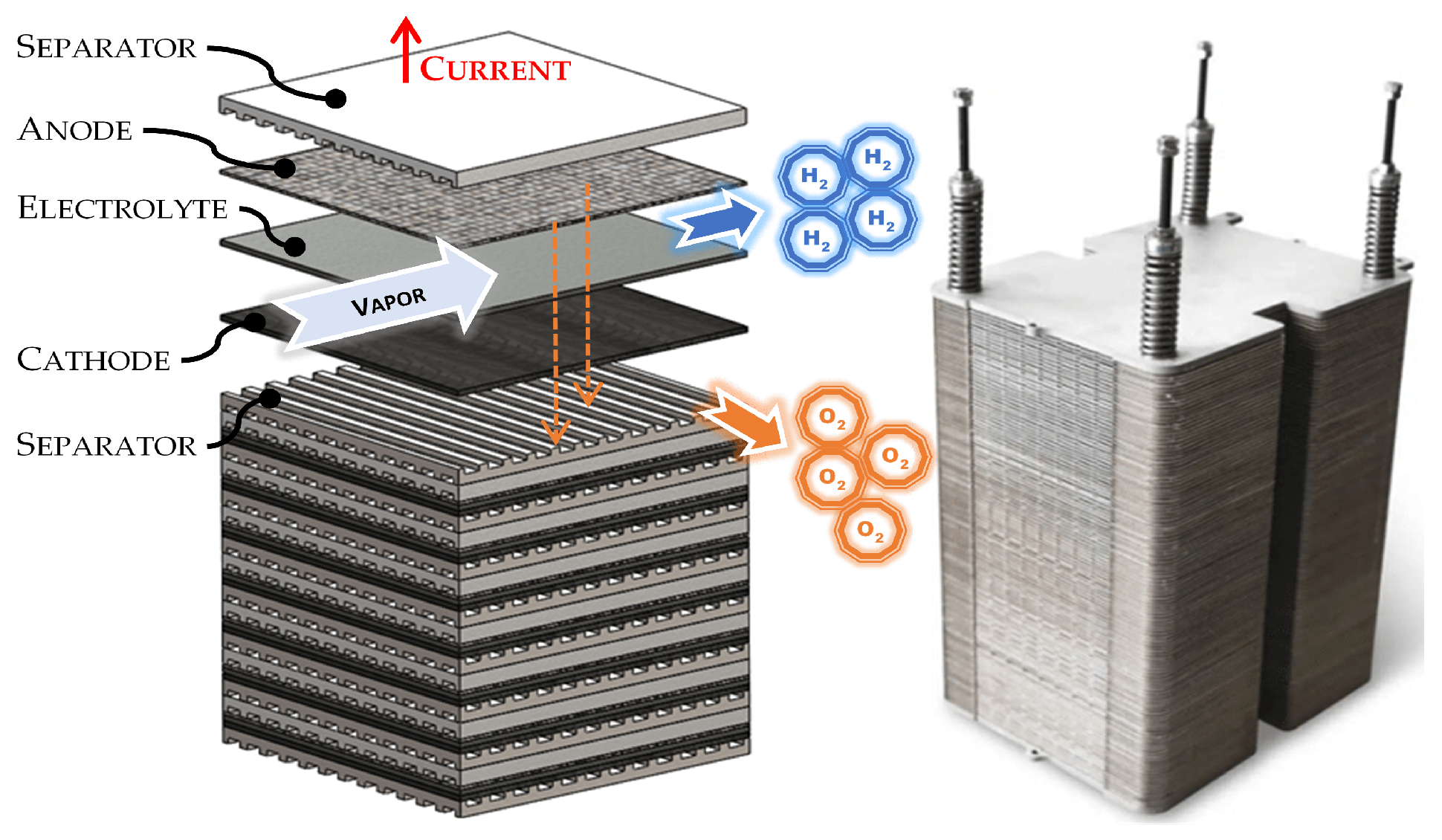
The growth of the human population combined with economic development leads to an increase in global energy consumption. Increasing energy consumption makes it more difficult to transition energy systems based on fossil fuels to low carbon energy sources []. Renewable energy sources such as solar energy, wind power, hydropower, bioenergy, and geothermal power are considered environmentally friendly technologies. Developing clean and sustainable energy systems is one of the most important problems facing the world in this century, with the aim of decreasing carbon dioxide emissions. The main renewable sources for green energy technologies, such as solar and wind sources, are variable sources with fluctuating nature. The integrated energy system can include smart combinations of technologies so that energy supply and demand are matched in both time and space []. Therefore, aiming to establish an energy system in green technology requires definitively a storage energy solution. An optional energy carrier can be considered to be the green hydrogen used also to store and transport renewable energy, thus playing a pivotal role in the global energy transition []. In the green energy system, the hydrogen is generated through electrolysis of water using electricity sourced from renewable sources, reducing dependence on fossil fuels and greenhouse gas emissions []. hydrogen energy systems have been examined in various studies as integrated green hydrogen production with a single energy source, or as hybrid renewable energy systems [,,,,,]. hydrogen can be produced via water electrolysis in multiple ways as: Alkaline Water Electrolyzers (AWE); Anion Exchange Membrane Water Electrolyzers (AEMWE); Proton Exchange Membrane Water Electrolyzers (PEMWE); Solid Oxide Electrolysis Cell (SOEC); Proton Conducting Ceramic Electrolyzers (PCCEL) []. However, low-temperature electrolysis requires electro catalysts based on noble metals and energy to split water into hydrogen and oxygen, resulting in low energy conversion efficiency and high cost of hydrogen production []. Electrolyzers at high temperature (500 °C–850 °C) based on a solid oxide electrolytic cell (SOEC) or a solid oxide fuel cell (SOFC) are considered a better solution due to the thermodynamic and electrochemical kinetic conditions of the reaction not limited by Carnot efficiency []. SOEC uses a solid and dense ceramic oxide membrane separator that conducts ions at elevated temperatures to split water in the form of steam into pure hydrogen and oxygen. Reversible solid oxide fuel cells (RSOFC) operate in both fuel cell and electrolysis modes as a reversible system characterized by high energy storage efficiency, environmental friendliness, low development cost and high market conversion rate [,,]. Generally, the SOEC is developed using multi-stack modules to increase production quality and heat distribution throughout the stack during operation (Figure 1). The specifics of SOEC/SOFC functionality at high temperatures require a thermal process of the incoming fluids. The electrolysis process comprises gas reaction of water and steam at an elevated operating temperature reaching up to 1000 °C and hot exhausted outgoing gases. Many studies focus on optimizing the thermal efficiency of the component Solid Oxide Electrolysis systems, particularly in the context of high-temperature steam generation [,,,,]. To improve the hydrogen production efficiency, theoretical models of SOECs for water electrolysis are developed to reveal the electrochemical and thermal characteristics. The analysis of thermodynamic performance can provide suggestions for more efficient use of heat waste. Recovery of steam water waste heat could improve hydrogen utilization and decrease the heat consumption.

Figure 1.
Solid oxide electrolyzer design schematics and stack.
In this study a set of comprehensive thermodynamic models is presented that use mathematical equations for the description of thermal energy transfer based on the amount of heat added to or removed from the system for heat recovery integrated within a SOEC system (that is, MODEL Elcogen E350 stack). The novelty of this study is to provide three concepts of thermal analysis, specifically the overall thermal heat demand, realized as block-based diagrammatic approaches in Simulink containing blocks and connections, performed on the SOEC system based on standard technical specification and nominal condition of the Elcogen E350 for the production of hydrogen. In particular in the first black-box modeling the total heat energy demand required by the SOEC system is calculated without waste heat recuperation. In the second model is contained the recirculation of waste heat using the low, middle and high module heat exchangers, while in the third design model the middle module heat exchanger is not included. The effective utilization and recovery of the thermal heat energy of outgoing fluids such as steam, water, hydrogen, and oxygen can improve the efficiency of the SOEC integration system for hydrogen production using heat exchangers to recover waste heat [,]. Specifically, high, middle, and low-temperature heat exchangers are used to handle heat transfer within the SOEC system []. Thermal models based on integrated high, middle, and low-temperature heat exchangers in an SOEC system are compared to a traditional general thermal model without thermal assistance from the waste heat recovery approach due to exhaust gas recirculation with a temperature exceeding more than 600 °C in the SOEC electrolyzer. The temperature values are based on Elcogen SOEC technology that operates at 600–700 °C with 1.67 kg of water for the production of hydrogen. The heat transfer equations were calculated using the specific Elcogen system. The black-box modelings in Simulink for the thermal equation models have involved the thermal analysis of processes and prediction of thermal heating performance in hydrogen production within the SOEC system for its future control strategy. The EC system assists SOEC hydrogen production, because they are focused on temperature, mass (i.e., water, steam water, oxygen and hydrogen) and heat without explicitly modeling internal heat transfer mechanisms such as conduction and radiation, heat losses, exergy balances that include Joule heating, reaction enthalpy, and heat leaks, neglecting the electrical power consumption in the electrolysis process and chemical/electrochemical reactions. The study aims to evaluate three concepts for the recovery of heat waste in a SOEC system. The assessment is theoretical, and examines major components as functional blocks, in order to obtain general parameters for each component to be used in further research activities.
The main contributions of this work include:
- A set of three mathematical theoretical models based on thermal heat equation that incorporates the concept of specific heat capacity developed for calculation of the thermal heat and cool in a SOEC system is proposed. In particular, a general thermal model excludes the waste heat recovery and it is focused just on heat transfer processes within a SOEC system. In the second thermal model is integrated in the SOEC system the high, middle, and low-temperature heat exchangers to recover waste heat of the hydrogen-water mixture. In the third model is integrated in the SOEC system the high and low-temperature heat exchangers to recover waste heat of the hydrogen-water mixture, oxygen and hydrogen.
- Three block diagram models in Simulink for a SOEC system integrated with and without high, middle, and low-temperature heat exchanger are proposed to enhance system efficiency and utilize the waste heat from the SOEC system.
The rest of this paper is organized as follows: in Section 2, the SOEC system is described and in Section 3 thermal equation models and block diagram models of thermal heat transfer are provided. The calculation results for a SOEC system is reported in Section 4. Finally, Section 5 and Section 6 refer to the discussion and conclusion of the work, respectively.
2. Materials and Methods
Description of Solid Oxide Electrolyzer Cell System
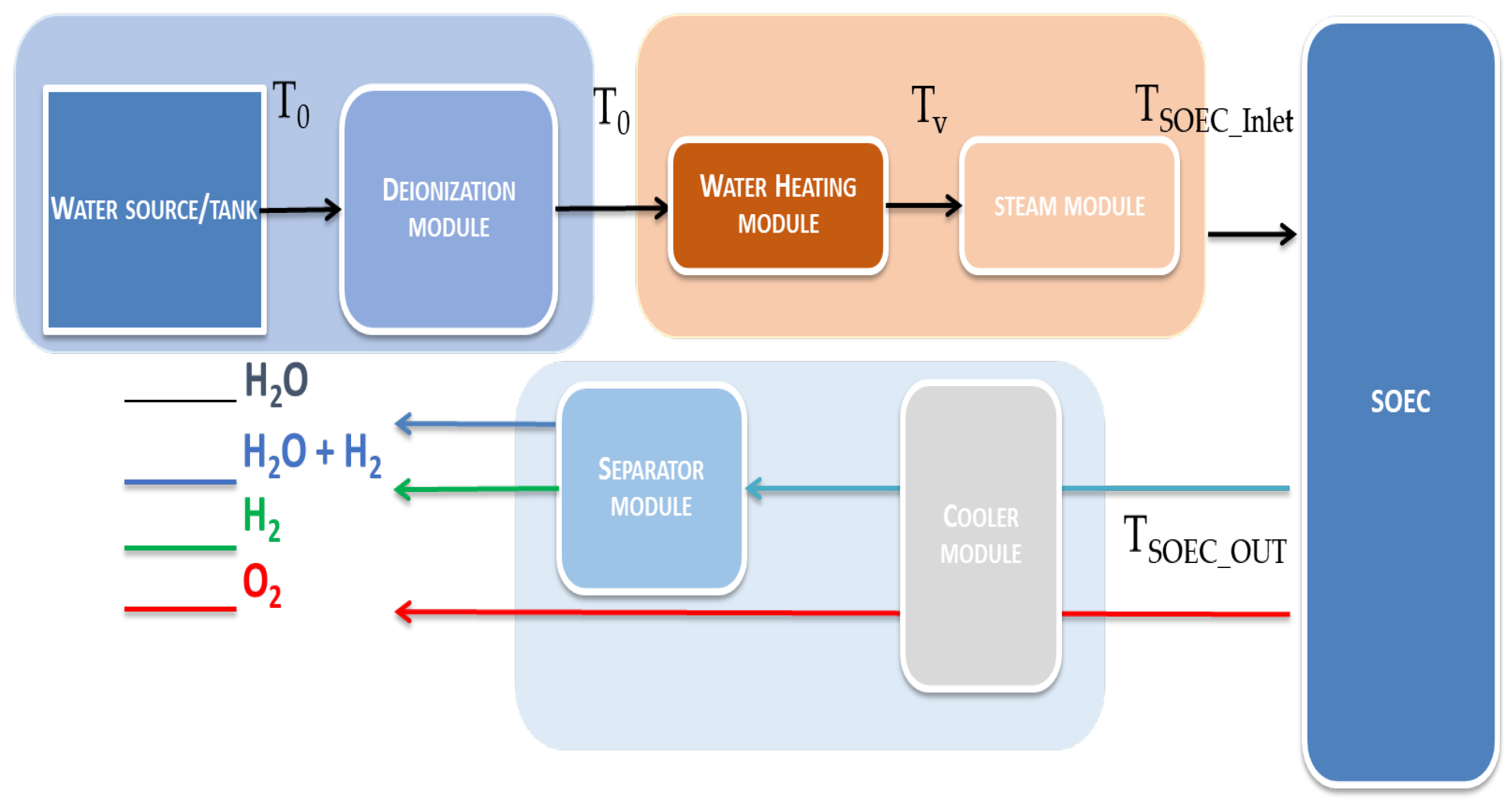
Generally the Solid Oxide Electrolyzer Cell (SOEC) system can be summarized in three subsystems: fluid treatment, SOEC and gas treatment shown in the generic block diagram layout Figure 2:

Figure 2.
Diagram of general conventional thermal heat transfer in SOEC preheating system.
In the Solid Oxide Electrolyzer Cell (SOEC) system the water electrolysis takes place by connecting the applied voltage to the cathode and anode cell electrodes and the electrochemical reaction splits the water into hydrogen and oxygen gases produced and separated as a pure gas stream. Initially, the process step consists in the deionization of the water in order to be free of metal ions; otherwise, metals can be accumulated and reduced at the anode, interfering with the chemical reaction. The product gas is a mixture of water vapor and hydrogen, with additional oxygen as a separate gas. Therefore, the hydrogen is transported out of the cell and then expelled in the gas separator. The heat is generated during the electrochemical reaction removed from the process by means of heat exchangers.
The fluid treatment subsystem is represented by the following modules (Figure 2):
- water source or tank that provides water for the system i.e., tap water, treated wastewaters as the water inlet sources by exploiting the possibility of operating in high-temperature conditions [,,,].
- deionization module is used to purify and deionize water by applying functional current to remove ionized substances from water.
- water heating module transforms the incoming water into steam vapor, requiring a significant high amount of energy for the phase change in the next steam module [,,,,,,]. The heating module can transform incoming water into steam vapor. The vaporization involves additional thermal energy to the water in order to changes into steam vapor.
- SOEC subsystem for electrolysis at high-temperature (700–1000 °C) electrochemical device that utilizes a solid oxide electrolyte to convert steam into hydrogen
- cooler module is used to cool down the mixture of hydrogen and steam water at high temperature in order to separate the hydrogen gas.
- separator module provides the physical separation of the hydrogen gas from the resultant steam water and oxygen gases. The membrane unit used to separate hydrogen gas from steam is made of solid polymer, Nafion or ceramic []. This module is the key for conducting protons of hydrogen gas with high purity to pass from the anode to the cathode. It is considered a “black box” constrained for its input and output characteristics in the thermal models proposed in the next sections.
3. Base Model Assessment: General Conventional Thermal Heat Transfer in SOEC System ()
The total thermal heat energy represents a critical parameter for the water splitting process in the electrolysis system for efficient production of hydrogen. In this work a theoretical concept of heat management is presented neglecting the electrical power consumption in the electrolysis process. It is assumed that SOEC can be considered as a system “black box” in the context of thermal modeling with inputs (temperature of water mass and water mass) and outputs (temperatures and mass of hydrogen, water and oxygen) without explicitly modeling internal chemical/electrochemical reactions and mechanisms as exothermic and endothermic mode. In fact, heat losses, radiation, and convection are neglected that play an important role in the thermal management and efficiency of SOEC system at high operating temperatures. The solid oxide stacks for electrolyser systems is considered the MODEL Elcogen E350 stack as shown in Figure 1 operates in a temperature region between 600 and 700 °C. It is composed of 15 unit cells, metallic interconnect plates, sealants, current collector plates, and transfer compression system. Stack dimensions measured from the current collector plates are: width 189 mm, length 311 mm, height 44.5 mm, weight 9 kg. Elcogen E350 stack is supplied without thermal insulation. Elcogen E350 solid oxide stack can recover approximately 117 MJ of heat energy from 1 kg of water, assuming a 650 °C operating temperature and considering the endothermic electrolysis reaction of water. The maximum and minimum voltages for Elcogen E350 are 18 V and 10 V, respectively, with a nominal current of 30 A []. However, in the context of the thermal analysis conducted, it is assumed as a “black box”. Elcogen has not publicly provided specific values for the thermoneutral voltage and heat generation of the E350 solid oxide stack. The mass of water is considered conservative in the closed SOEC system. The total water mass entering SOEC is equal to the water mass H2O∼1.67 kg at high temperature 700 °C in the inlet of SOEC stack. The gas outlet is composed by steam water H2O∼0.67 kg, a mixture of H2∼0.125 kg and O2∼0.875 kg leaving the SOEC. The mass balance can be summarized as follows:
- In SOEC inlet the mass is 1.67 kg of H2O
- In SOEC outlet the mass is 1.67 kg equal to sum of 0.67 kg of H2O, 0.125 kg of H2 and 0.875 kg of O2.
In fact, the steam water is mixed with hydrogen and oxygen which will be separated. The steam water enters the electrolyzer at temperature 600 °C and, the water with steam of hydrogen and oxygen comes out at temperature 700 °C. In the context of the theoretical hypothesis of the principle of conservation of mass and isobaric condition: the total demand for heat energy in the electrolysis system (Equation (1)) is expressed in kJ by the following equation:
The total demand for heat energy is approximately a sum of the three thermal components: , , and .
is the thermal energy demand to preheat the incoming deionized water at room or ambient temperature (i.e., ∼25 °C) to certain vaporization temperature (i.e., ∼100 °C) as expressed in Equation (2):
where is the mass of the water, is the room temperature of the incoming tap water, is the temperature of transitions from a liquid water to a gaseous state at the boiling point of 100 °C, expressed in J/(kg·K) is the specific heat capacity of the liquid water averaged across the difference of room temperature and the vaporization temperature of the water .
The second term is the total latent heat energy of the liquid-steam phase transition as expressed in Equation (3):
where expressed in kJ/kg is the latent heat of vaporization. The third component is the thermal energy to heat the steam-water to the high requested temperature (i.e., ∼600 °C) at the input of the SOEC module as reported in Equation (4):
where is the electrolyzer operating temperature at the SOEC inlet as commonly called the stack temperature inlet and, expressed in J/(kg·C) is the specific heat capacity of steam water averaged across the difference between the vaporization temperature () and the electrolyzer operating temperature (). In Figure 2 the traditional general thermal model is considered to be not accurate and efficient because the heat from the outlet fluids to preheat is completely wasted in the SOEC system. In fact the thermal energy transfer has in this case just a positive value and heat is added to the SOEC system, causing its potential increases in temperature. If or some of its components are negative, the heat is removed from the system and potentially can indeed lead to a decrease in the system’s temperature, and it can be considered waste heat if it is not utilized for any useful purpose. In order to obtain a process of direct integration and utilization of heat in the SOEC system, two simplified thermal model energy solutions.
3.1. Thermal Heat Transfer in SOEC System with Low, Middle and High Module Heat Exchangers ()
In the second model of heat integration in hydrogen production processes, new blocks such as heat exchangers are included between the deionization and the SOEC process. The variant model presents three heat exchangers at different operating temperatures Low, Medium, and High to decrease the thermal energy utilization of the process and a hydrogen separation process using steam water at high temperatures. The water from the waste steam is recirculated within the separator system.
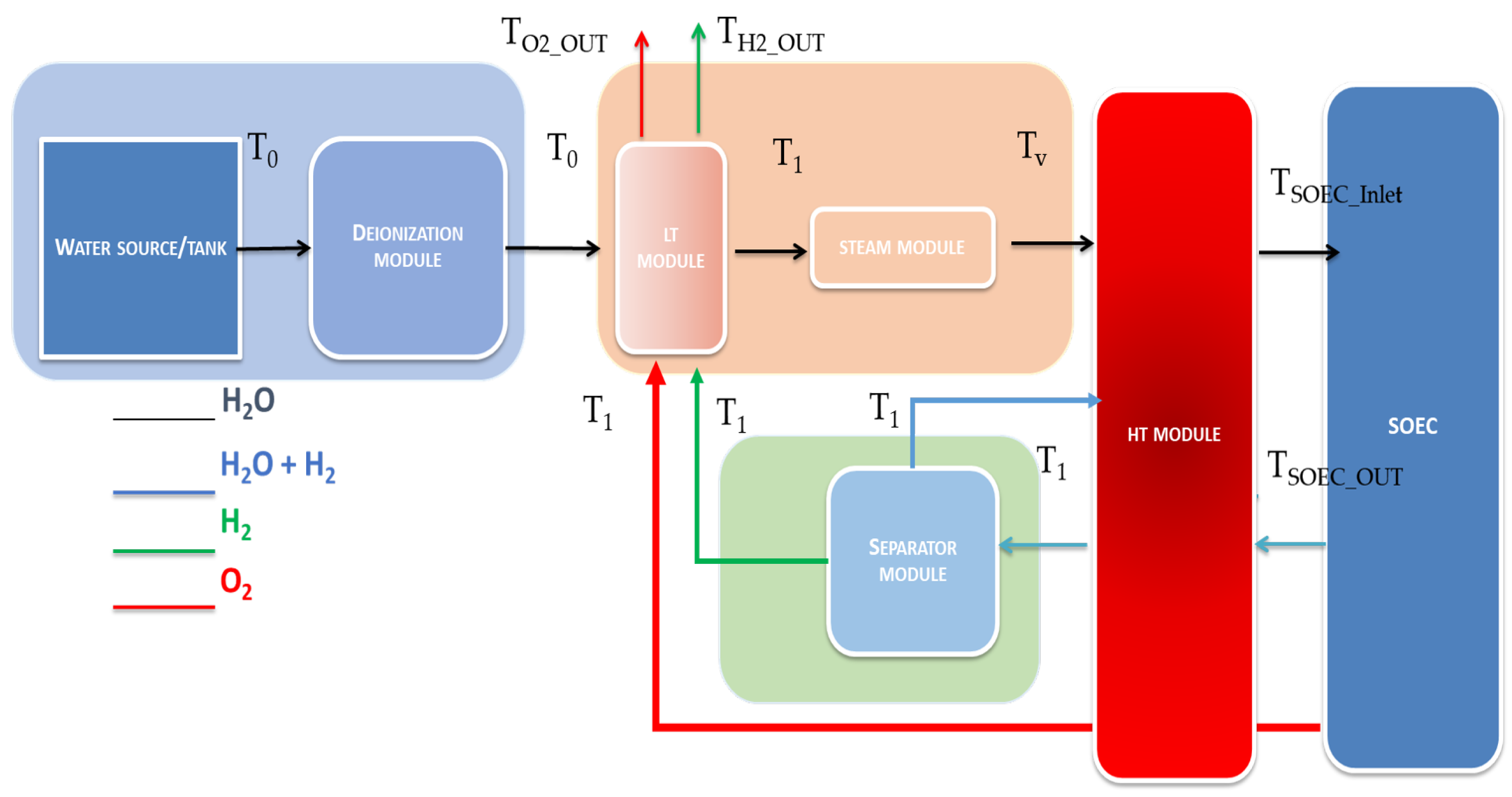
Using waste heat from outlet steam water and hydrogen to preheat the process after deionization is a highly effective method to improve energy efficiency and reduce overall thermal energy consumption. This can be achieved through three heat exchangers that allow for the reuse of steam water that would otherwise be lost to the environment. In the electrolyzer system, three heat exchangers (low middle and high modules) located after the water treatment as reported in Figure 3 are considered “black boxes” and the specific detail and design are ignored. In the SOEC outlet (that is, the Elcogen E350 stack), the constituent elements are oxygen and a mixture of steam (water vapor) and hydrogen at a high temperature of approximately 700 °C. The temperature of oxygen and steam mixture is decreased in the heat exchanger (high module) as heat is transferred from the fluids to the heat exchanger’s cooling medium. The oxygen at temperature of 130 °C is re-used to preheat the water fluid that has ambient temperature 25 °C in the heat exchanger (Low module) and recover the waste heat in order to be cooled at temperature 30 °C in the heat exchanger. The separator module is used to split the hydrogen from the steam. The steam water (i.e., at temperature of ∼130 °C) is reused in heat exchanger (high module) and the hydrogen temperature is gradually cooled to low temperature (∼30 °C) within a heat exchanger (middle module). The thermal energy demand is calculated by considering the heat transfer and reused or recycled waste heat in the heat exchangers.

Figure 3.
Diagram of Thermal heat transfer in SOEC system with heat exchangers (Low, Middle and High Module).
The total heating energy demand in the SOEC system (Equation (5)) is expressed in kJ by the following equation:
where , and are considered the thermal energy demand for the low, middle and high modules-heat exchangers respectively. In the heat exchanger, Low Module (LT Module), designed at low-temperature, the thermal energy demand in kJ to preliminary heat of incoming deionized water at room or ambient temperature (i.e., ∼25 °C) to certain temperature (i.e., ∼50 °C) expressed by in Equation (6):
where is the mass of water, is the room temperature of the incoming tap water, is the temperature at the outlet of the LT module (∼50 °C), expressed in J/(kg·C) is the specific heat capacity of the liquid water averaged over the difference of room temperature and temperature at the outlet of the LT module.
In the middle heat exchanger (MT Module) designed at middle-temperature, the thermal energy demand in kJ is necessary to heat up the water to more high temperature (i.e., ∼95 °C) expressed by in Equation (7):
where is the mass of water, is the temperature at the outlet of the MT module (∼95 °C), expressed in J/(kg·C) is the specific heat capacity of liquid water averaged in the difference between temperatures and .
In the high Module (HT Module) heat exchanger, designed at high-temperature, the thermal energy demand in kJ includes the vaporization and heating of water at the inlet of the SOEC module expressed by Equation (8):
The term is the thermal energy demand necessary to heat the steam water at the inlet of the SOEC system to a certain vaporization temperature (that is, ∼100 °C) expressed by in Equation (9):
where is the mass of water heated to vapor in the HT module; is the vaporization temperature of 100 °C, expressed in J/(kg·C) is the specific heat capacity of liquid water averaged across the difference of and the vaporization temperature of water .
The second term is the total latent heat energy of the liquid-steam phase transition expressed in Equation (10):
where expressed in kJ/kg is the latent heat of vaporization. The third term is the thermal energy to heat the steam from the MT module to the high requested temperature (that is, ∼600 °C) at the inlet of the SOEC module as reported in Equation (11):
where is the electrolyzer operating temperature at the inlet of SOEC and is the vaporization temperature, expressed in J/(kg·C) is the specific heat capacity of steam water averaged across the difference of the vaporization temperature () and the electrolyzer operating temperature at the inlet (∼ 600 °C).
In the HT module, it is necessary to add another term of thermal energy referred to to heat the steam water from the separator component () up to temperature at the inlet SOEC (∼600 °C) as reported in Equation (12):
where is the the electrolyzer operating temperature at the inlet of SOEC and is the outlet temperature of HT module, expressed in J/(kg·C) is the specific heat capacity of steam water averaged across the difference of the outlet temperature of HT module () and the electrolyzer operating temperature at the inlet ().
In the SOEC system a considerable amount of thermal energy is consumed and hot gases as steam water, hydrogen and oxygen are produced at high temperature (i.e., ∼700 °C). This heat can be used to preheat the incoming water mass within the low and middle module exchanger reducing the energy thermal consumption. By recycling of steam water it is necessary to calculate the cooling energy demand required at the output of SOEC system, specially in the separation module responsible of separation of hydrogen from steam water. The total cooling energy demand in the SOEC system (Equation (13)) is expressed in kJ by the following Equation (13):
where , and are considered the cooling energy demand for the incoming fluids (steam water, hydrogen and oxygen) at the low, middle and high modules-heat exchangers.
In SOEC system the steam water at the outlet of the separator module is recycled back to the HT Module in an closed-loop system. The temperature of the mixture steam water and hydrogen vapor exiting at the outlet of SOEC module () decreases to so that the cooling process is involved to heat transfer to the HT module. A contribution amount of energy occurring in the HT module is a sum of released energy when the outgoing steam water from SOEC module decreases the temperature to and the outgoing hydrogen from SOEC module decreases the temperature to , as reported in Equation (14):
with
and
where and expressed in J/(kg·C) contribute as the specific heat capacity of steam water and hydrogen averaged across the difference of the outlet temperature of HT module () and the temperature at the outlet (). and are respectively the hydrogen mass (i.e., 0.125 kg) and the water steam mass (i.e., 0.67 kg).
The separation module produces hydrogen at high temperature (i.e., ∼130 °C) and the generated heat can be recycled in the Middle Module. The cooling energy demand for hydrogen in MT module is:
where expressed in J/(kg·C) contribute as the specific heat capacity of hydrogen averaged across the difference of the outlet temperature of separation module and the temperature at the outlet () and is the hydrogen mass (i.e., 0.125 kg).
The output of SOEC is also oxygen gas at high temperature (i.e., ∼700 °C) that can be recycled in HT ad LT Module efficiently. The amount of cooling energy demand for oxygen in LT and HT modules is expressed as a sum of cooling energy demands in LT () and HT modules ():
with
and
where and expressed in J/(kg·C) contribute as the specific heat capacity of oxygen averaged across the difference of the outlet temperature of HT module () and the temperature at the outlet (), and the difference of the outlet temperature of HT module () and the temperature of oxygen when leaving the system (). is oxygen mass (i.e., 0.875 kg).
The energy needed to maintain the process of SOEC system supply can be calculated by considering the amount of thermal energy demand (Equation (5)) and the cooling demand (Equation (13)) as following in the Equation (21):
3.2. Thermal Heat Transfer in SOEC System with Low and High Module Heat Exchangers ()
In third theoretical thermal model design, the middle section module heat exchanger is removed and the thermal integration of the low and high modules is provided in the general preheating system of SOEC (Figure 4). The exhaust streams of hydrogen and oxygen are included as output in the low temperature module section that produces directly the gases at low temperature ( = 30 °C) affecting the overall efficiency and operating conditions of the system. This means that the temperature at which hydrogen is separated is lower for the condensation of water steam to a liquid state. So, the thermal balance calculations in the SOEC process will be changed.

Figure 4.
Diagram of thermal heat transfer in SOEC system with Low and High Module heat exchangers.
The low module (LT) heat exchanger preheat the incoming water and recover the waste heat of oxygen and hydrogen from separator module at operating temperature (∼95 °C) as in Equation (6). The heat energy demand in the SOEC system (Equation (22)) is expressed in kJ by the following equation:
where and are considered the thermal energy demand for the low- and high-module heat exchangers, respectively. In the heat exchanger, Low Module (LT Module), designed at low-temperature, the thermal energy demand in kJ to the preliminary heat of the incoming deionized water (∼1 kg) at room or ambient temperature (that is, ∼25 °C) to temperature (i.e., ∼95 °C) more higher than the temperature in the second theoretical model (Equation (6)). In the high Module (HT Module) heat exchanger, designed at high-temperature, the thermal energy demand in kJ includes the vaporization and heating of water at the inlet of the SOEC module expressed by Equation (23):
The term of Equation (23) is the thermal energy demand necessary to heat the steam water at the inlet of SOEC system to the vaporization temperature (i.e., ∼100 °C) expressed by in Equation (24):
where is the sum of the water mass heated to vapor in the HT module and the recirculated water of SOEC; is the vaporization temperature of 100 °C, expressed in J/(kg·C) is the specific heat capacity of liquid water averaged across the difference between the temperature of incoming water and the vaporization temperature of the water .
The second term is the total latent heat energy to evaporate the water mass expressed in Equation (25):
where expressed in kJ/kg is the latent heat of vaporization. The third term is the thermal energy required to evaporate the water at the input of the SOEC module to a temperature of ∼600 °C as reported in Equation (26):
where is the electrolyzer operating temperature at the inlet of SOEC and is the vaporization temperature, expressed in J/(kg·C) is the specific heat capacity of the steam water averaged across the difference of the vaporization temperature () and the electrolyzer operating temperature at the inlet (∼600 °C). In the HT module, it is necessary to add another term of thermal energy referred to to heat the steam water from the separator component () up to temperature at the inlet SOEC (∼600 °C) as reported in Equation (27):
where is the electrolyzer operating temperature at the inlet of SOEC and is the outlet temperature of the HT module, expressed in J/(kg·C) is the specific heat capacity of the steam water averaged across the difference of the outlet temperature of HT module () and the electrolyzer operating temperature at the inlet ().
In the SOEC system, a considerable amount of thermal energy is consumed and hot gases such as steam water, hydrogen, and oxygen are produced at high temperature (i.e., ∼700 °C). This heat can be used to preheat the incoming water mass within the low and middle module exchanger reducing the energy thermal consumption. By recycling of steam water it is necessary to calculate the cooling energy demand required in the output of the SOEC system, especially in the separation module responsible for the separation of hydrogen from steam water.
The total demand for cooling energy in the SOEC system to heat the incoming fluids is expressed in kJ by the following Equation (28).
where
Each term is considered the cooling energy demand for the incoming fluids at the high module-heat exchanger. In SOEC system, the steam water at the outlet of the separator module is recycled back to the HT module in a closed-loop system. The temperature of the mixture of steam water and hydrogen vapor that exits the outlet of the SOEC module () decreases to so that the cooling process is involved to transfer heat to the HT module. A contribution amount of energy occurring in the HT module is a sum of the energy released when the steam water from the SOEC module decreases the temperature to and the outgoing hydrogen from SOEC module decreases the temperature to , as reported in Equation (30):
where is the temperature of the incoming fluid, is the vaporization temperature, and is the outlet temperature of SOEC system; , and expressed in J/(kg·C) contribute as the specific heat capacity, respectively, of steam water, water and hydrogen averaged across the difference of temperatures range; , are respectively the hydrogen mass (that is, 0.125 kg) and the water steam mass (i.e., 0.67 kg). The separation module produces hydrogen at high temperature (that is, ∼95 °C) and the heat generated can be recycled in the Low Module. The cooling energy demand for hydrogen in LT module is:
where is the temperature of the fluid that enters the separation module and is the temperature of hydrogen when leaving the system; expressed in J/(kg·C) contribute as the specific heat capacity of hydrogen averaged across the difference of the inlet temperatures ) and of the LT module and is the hydrogen mass (i.e., 0.125 kg).
The output of SOEC is also oxygen gas at high temperature (i.e., ∼95 °C) that can be recycled in LT Module efficiently. The amount of cooling energy demand for oxygen in LT module is expressed as:
where expressed in J/(kg·C) contribute as the specific heat capacity of oxygen averaged over the difference between the outlet temperature of the HT module () and the temperature of oxygen when leaving the system (). is oxygen mass (i.e., 0.875 kg).
The energy needed to maintain the SOEC process is:
4. Results
According to the scope of this study, the three thermal models presented are implemented using the Simulink environment of MATLAB R2025a that provides the components of the SOEC system. Thermal models are represented as block diagrams connected by signal lines and are used to calculate and simulate mathematical equations that describe heat and cool transfer and can be simulated to predict the response of the SOEC system.
4.1. First Thermal Heat Model ()
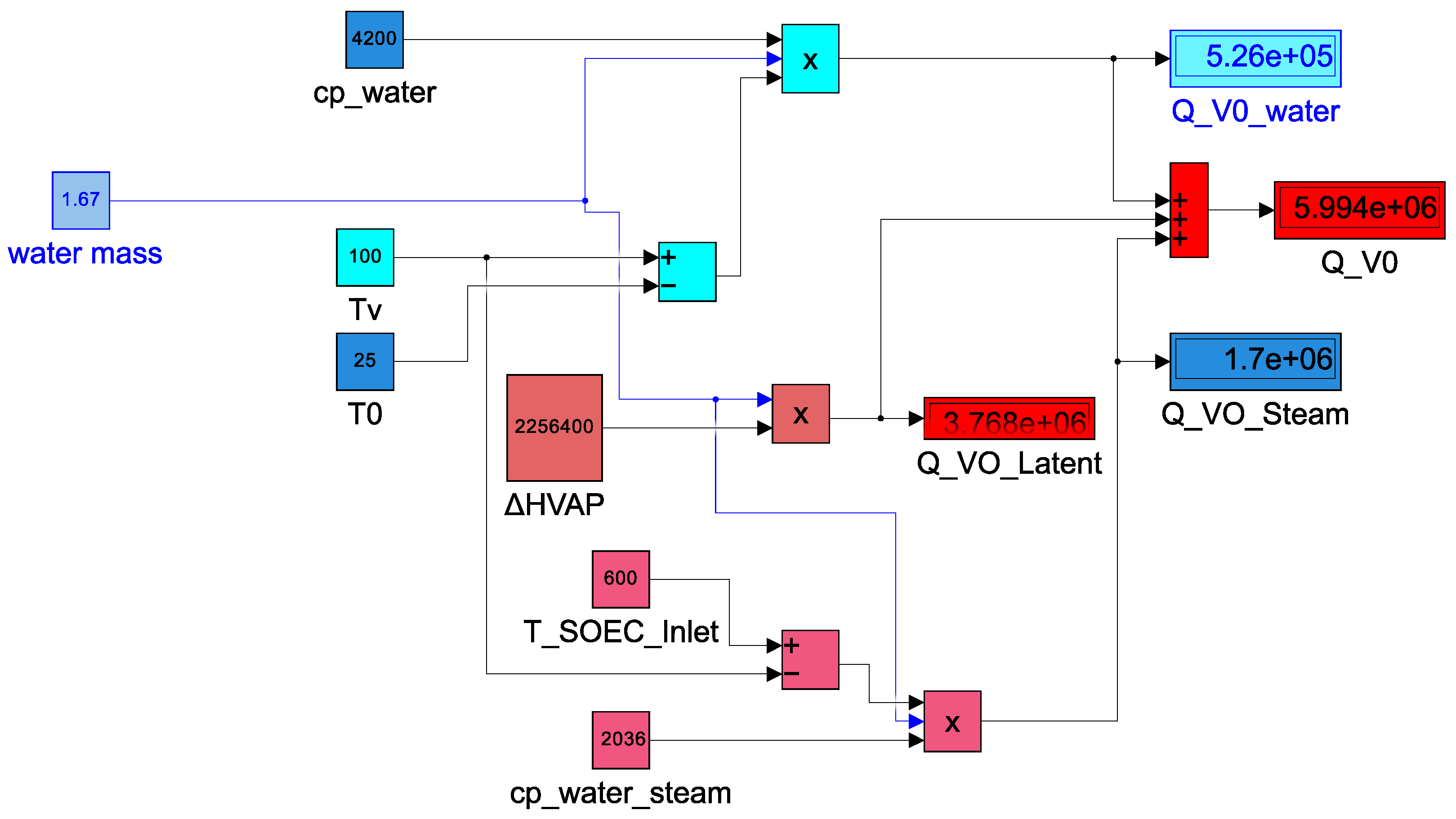
In the first proposed thermal model, the calculation of the total demand for heat energy for the electrolysis system without recirculation of waste heat based on Equation (1) in the solid oxide stacks for electrolyser systems is considered the MODEL Elcogen E350 stack. In Simulink block diagram, the parameters presented as input are:
- the water mass is 1.67 kg used as an input for the SOEC module
- the ambient temperature () is 25 °C, the vaporization temperature () is 100 °C and is 600 °C indicated by the manufacturer of Elcogen E350 stack
- the specific heat capacity of water () is described in the Figure 5 as equal to 4200 J/(kg·C) in the range temperature of to and the specific heat capacity of steam water from to
- is 2256.4 kJ/kg

Figure 5.
Simulink block diagram of general conventional thermal heat transfer in SOEC preheating system ().
4.2. Second Thermal Heat Transfer Model with Low, Middle and High Module Heat Exchangers ()
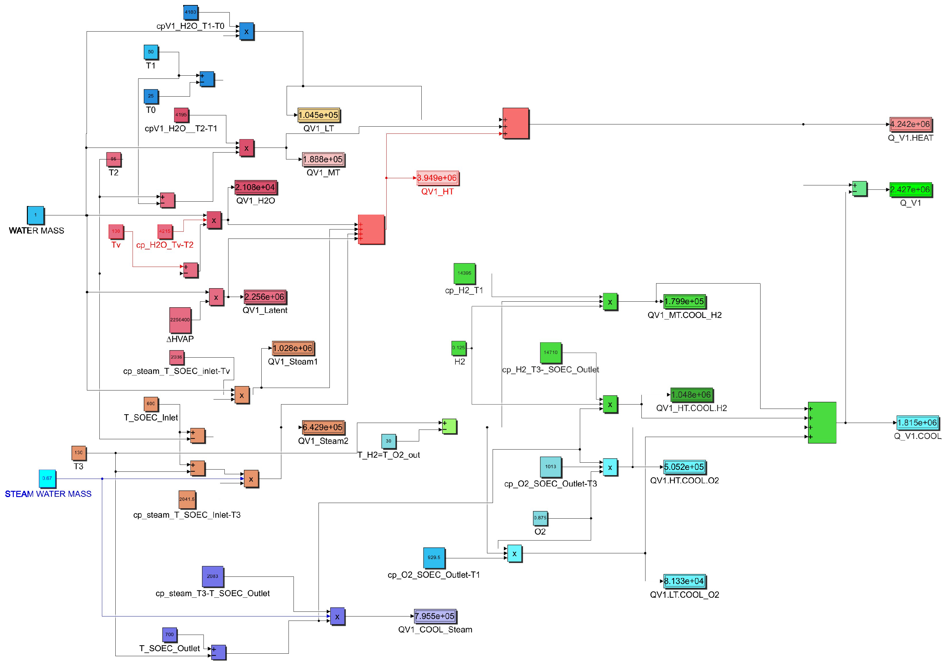
In the second thermal/cooling model is proposed the calculation of the total thermal energy and cooling demand for the MODEL Elcogen E350 stack system with recirculation of waste heat based on Equation (33). The specific heat capacity parameters used in the Simulink block diagram are reported in Table 1. In SOEC System block diagram based on model Elcogen E350 stack, the temperatures considered are the ambient temperature of 25 °C, the temperature at LT module outlet of 50 °C, the temperature at MT module outlet of 95 °C, the vaporization temperature is 100 °C, the temperature of steam water before its inlet in the HT module is 130 °C, the temperature of oxygen and hydrogen when leaving the system are respectively and , and the SOEC operating temperatures and are 600 °C and 700 °C respectively indicated by the manufacturer of Elcogen E350 stack. In the Elcogen E350 solid oxide electrolyzer system, tap water is used as a starting material of 1 kg to produce 0.125 kg hydrogen. At the entrance of SOEC electrolyzer the steam water is of 1.67 kg. It splits this steam water at the outlet of SOEC into water (0.67 kg), hydrogen (0.125 kg), and oxygen (0.875 kg). The specific heat capacity parameters in the temperature range used in the computational model as reported in Table 1 are integrated over time using the values described in [,,].

Table 1.
The values of specific heat capacity for thermal model .
The heat energy is 4231.62 kJ, the recuperated cooling energy is 2430.15 kJ, the overall needed energy is 1801.47 kJ as shown in Figure 6. The Simulink block model shows the implementation of all equations (Equations (5)–(17)) reported in Section 3.1.

Figure 6.
Simulink block diagram of thermal heat transfer in SOEC system low, middle, and high-temperature heat exchangers ().
4.3. Third Thermal Heat Transfer Model with Low and High Module Heat Exchangers ()
In the second thermal/cooling model of the Simulink block diagram is proposed the calculation of the total thermal and cooling energy demand for the MODEL Elcogen E350 stack system with the recirculation of waste heat with components of low module and high module. In SOEC System block diagram based on model Elcogen E350 stack, the temperatures considered are the ambient temperature of 25 °C, the temperature at LT module outlet of 95 °C, the vaporization temperature is 100 °C, and are respectively the temperature of oxygen and hydrogen with the same value of 30 °C leaving the system, and the SOEC operating temperatures and are 600 °C and 700 °C respectively indicated by the manufacturer of Elcogen E350 stack. In the Elcogen E350 Solid Oxide Electrolyzer system uses tap water as a starting material of 1 kg to produce hydrogen of 0.125 kg. At the entrance of SOEC electrolyzer the steam water is of 1.67 kg. It splits this steam water at the outlet of SOEC into water (0.67 kg), hydrogen (0.125 kg), and oxygen (0.875 kg). The specific heat capacity parameters in the range of temperature used in the computational model as reported in the Table 2 are integrated over time using the values described in [,,].

Table 2.
The values of specific heat capacity for thermal model .
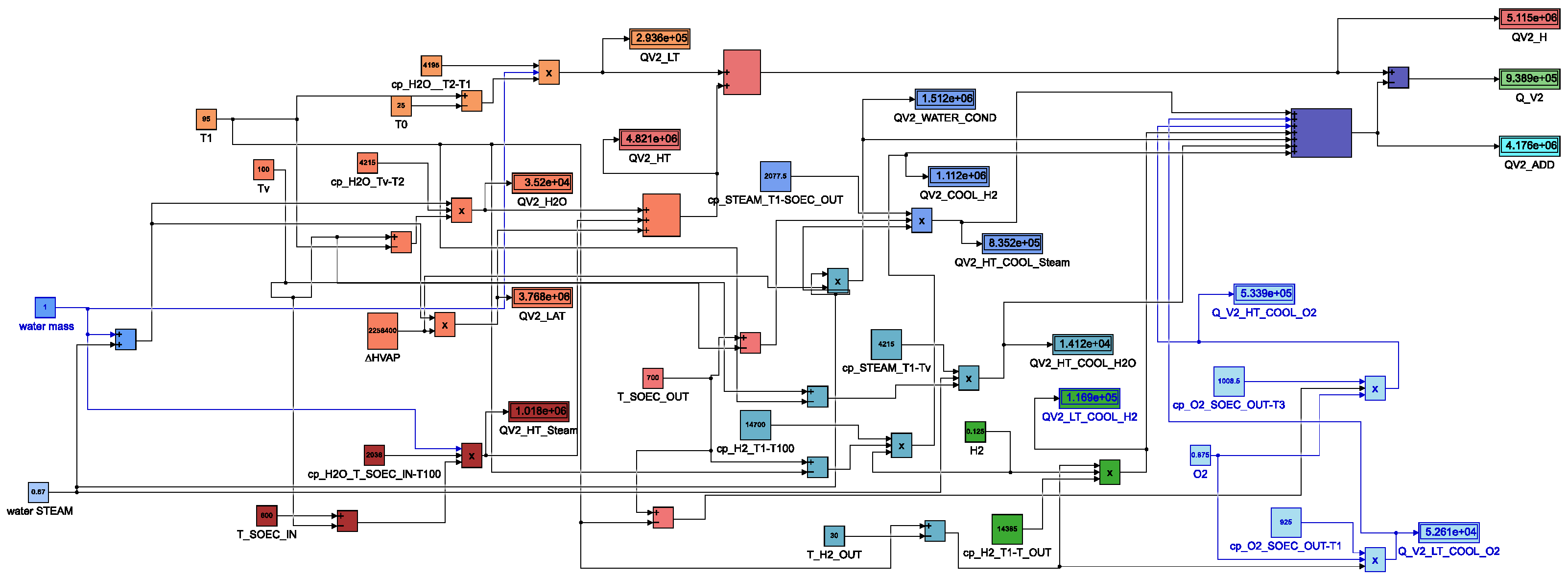
The heat energy is 5115.03 kJ, the recuperated cooling energy is 4176.11 kJ, the overall needed energy is 938.92 kJ as shown in Figure 7. The Simulink block model shows the implementation of all equations (Equations (22)–(33)) reported in Section 3.2.

Figure 7.
Simulink block diagram of thermal heat transfer in SOEC system with Low and High temperature heat exchangers ().
5. Discussion
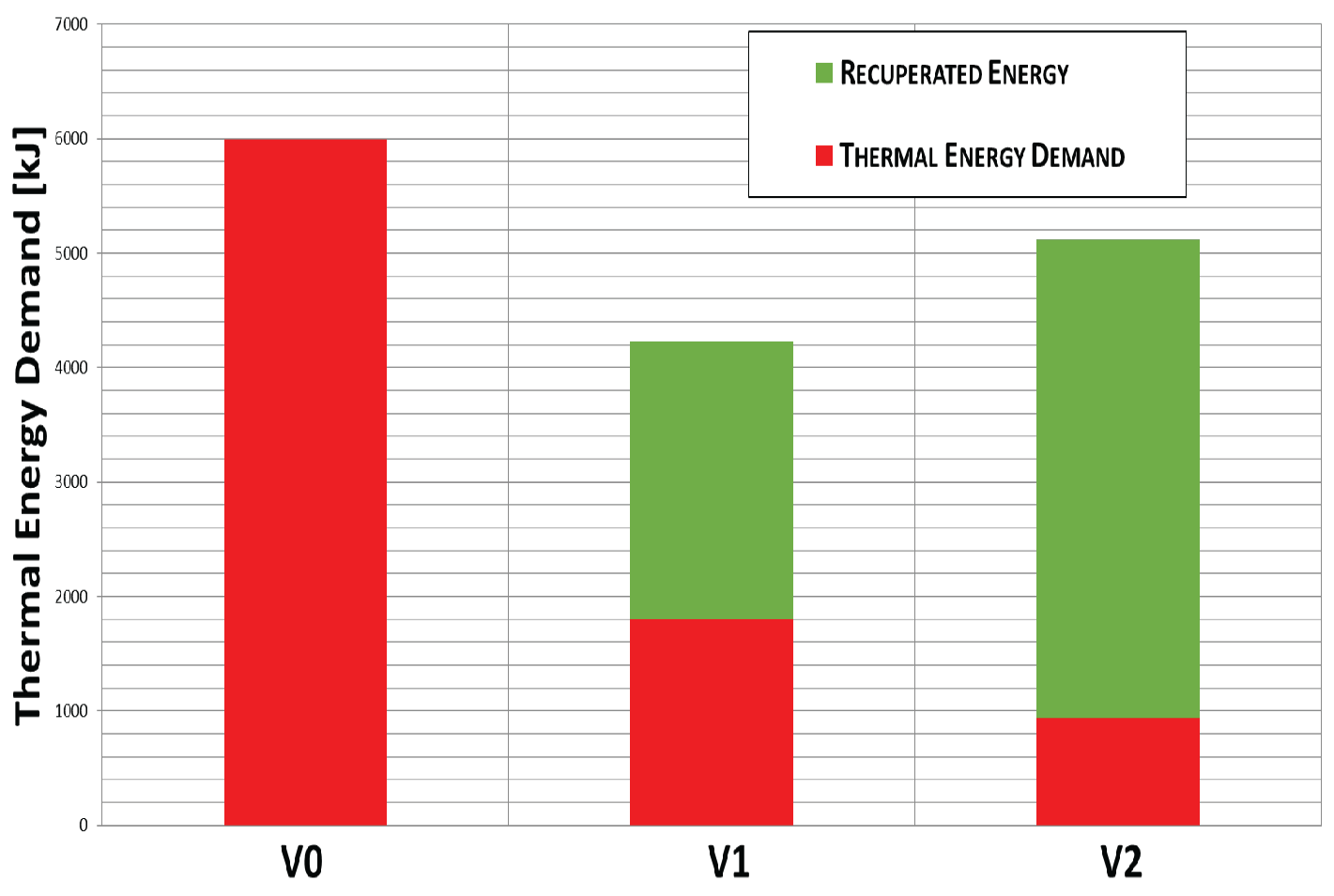
The thermal energy demand required for hydrogen production using MODEL Elcogen E350 stack expressed in percentage is 100% corresponding to ∼5994.3 kJ for first model in the absence of heat recirculation, 30% corresponding to ∼1801.47 kJ for second model with Low, Middle and High Module heat exchangers with the recuperated cooling energy and 16% corresponding to ∼938.92 kJ for third model with Low and High Module heat exchangers with the recuperated cooling energy. As observed in Figure 8 the first thermal theoretical model of SOEC system () requires an heating process with highest energy, (), nearly 5994.3 kJ for a water mass of 1.67 kg. Essentially, the heat recovery proposed in other thermal/cooling models ( and ) ensures that the thermal energy ( and ) is not wasted as in the traditional heating process of the SOEC system, making it more energy efficient. Therefore, the heated amount of water is decreased, because a portion of the steam water (0.67 kg) is recycled and the heat of the outgoing fluids is used to heat the incoming water, so the overall amount of thermal energy needed for the process is significantly decreased. In the second theoretical model the steam water is recycled avoiding the change of state and the potential loss of energy. However, its main weakness is the separation module that is required to perform a separation of hydrogen from steam water at high temperature, especially, for the challenging requirement. Additionally, it does not recuperate high energy and has an MT heat exchanger as an intermediate module. Finally, the third theoretical model could be considered the most efficient due to the highest energy recovery in the SOEC system, in fact, from the phase change of the water from vapor to liquid as it passes through a high temperature heat transfer module releasing a significant amount of latent heat, which can then be utilized by the system. Nevertheless, this thermal process involves double phase change vaporization and condensation (i.e., the same water is vaporized in HT module) and more recuperated high energy in the SOEC system. The hydrogen separation is performed at low temperature compared to model . Probably capturing more energy can lead to some additional losses that are not included in the developed theoretical thermal model of SOEC system. The primary losses are related to the technical realization of the concept (pressure regulation, water circulation, etc.). Other limitations regard the modeling of complex system and inaccurate data like heat loads, material properties, adiabatic restrictions, temperature distribution and boundary conditions that can significantly impact the model accuracy. Although the conceptual variants can be considered as theoretical energy models of heat recuperation for maximizing SOEC systems efficiency. The future research can be focused on accurate heat exchanger calculations, hydrogen separation and a detailed engineering design solution of the entire system including the selection components such as for low temperature solution could be used membranes or other mechanisms that are available on the market [,,,,].

Figure 8.
Thermal/Cooling heat transfer in the analyzed model design SOEC system.
6. Conclusions
Emerging need for energy balancing systems and the development of reversible fuel cell/electrolyzer systems require an effective solution. Current study evaluates the possibility for energy recuperation and fluid heat recuperation as decrease of needed energy for the process. It gives a quantitative ranking of examined variant models and defines the next stages of the process to reach an effective system. In particular is proposed the calculation of total energy thermal based on temperature changes in Simulink for the MODEL Elcogen E350 stack system without and with the recirculation of waste heat using the low middle and high module heat exchangers. In the second thermal model the overall heat energy is 1801.47 kJ with the recuperated cooling energy of 2430.15 kJ compared to the total heat energy demand of ∼5994.3 kJ in the first model with the absence of heat recirculation. However the most efficient theoretical model (the third one) has revealed the highest energy recovery (938.92 kJ) in the SOEC system using only the low and high module heat exchangers compared to other proposed thermal models. Thus, the heat and cooling demand are reduced to improve overall performance. The approximate thermodynamic models are referred to the SOEC MODEL Elcogen E350 stack and the results of the nominal test conditions reported in []. According to the selected system architecture, the SOEC stack is based on state-of-the-art material and standard technical specification of the Elcogen E350 that can operate at a nominal temperature as low as 600–700 °C. However, the performance of the system is more simplistic and conceptual due to the theoretical concept of heat management that has neglected electrical power consumption in the electrolysis process, the chemical/electrochemical reactions and mechanisms such as exothermic and endothermic mode, heat losses, radiation and convection. The thermal mathematical models can offer only simplified representations of real SOEC systems using mathematical equations and relationships to describe and predict thermal and cool heat to better understand the concept of thermal heat to help SOEC hydrogen production. However, it is also true that this study is not based on experimental data and reflects limitations in terms of industrial applicability requirements. In fact, the thermal energy demand required for hydrogen production, using the recuperated cooling energy involving the heat exchangers of the low and high modules, expressed in percentage, is 16%. The last value is very low compared to the significantly higher number of studies of hydrogen production focused on its production reporting electrical efficiency of 50% with thermal efficiency of 70% [,]. Therefore, current scientific activities are related to selection of components for the separation module, the design of the necessary heat exchangers and the integration of the fuel cell into the system. The presented study is an initial step in a process to develop reversible solid oxide fuel cell technology that is expected to achieve high energy efficiency.
Author Contributions
Conceptualization, G.D.T.; methodology, T.T. and K.K.; software, G.L.S.; validation, T.T., K.K. and G.L.S.; formal analysis, G.D.T. and T.T.; investigation, T.T.; resources, G.D.T. and T.T.; data curation, K.K. and G.L.S.; writing—original draft preparation, T.T., K.K. and G.L.S.; writing—review and editing, T.T., K.K. and G.L.S.; visualization, K.K.; supervision, G.D.T.; project administration, G.D.T.; funding acquisition, G.D.T. All authors have read and agreed to the published version of the manuscript.
Funding
This work has been realized with financial support by the European Regional Development Fund within the Operational Program “Bulgarian national recovery and resilience plan”, Procedure for direct provision of grants “Establishing of a network of research higher education institutions in Bulgaria”, under the Project BG-RRP-2.004-0005 “Improving the research capacity and quality to achieve international recognition and resilience of TU-Sofia”.
Informed Consent Statement
Not applicable.
Data Availability Statement
The data presented in this study are available on request from the corresponding author. The data are not publicly available due to relation to public funding details.
Conflicts of Interest
The authors declare no conflicts of interest.
Abbreviations
The following abbreviations are used in this manuscript:
AWE | Alkaline Water Electrolyzers |
AEMWE | Anion Exchange Membrane Water Electrolyzers |
HT | High Temperature (module) |
LT | Low Temperature (module) |
MT | Mid Temperature (module) |
PCCEL | Proton Conducting Ceramic Electrolyzers |
PEMWE | Proton Ex-change Membrane Water Electrolyzers |
RSOFC | Reversible Solid Oxide Fuel Cell |
SOEC | Solid Oxide Electrolysis Cell |
SOFC | Solid Oxide Fuel Cell |
References
- Yan, Z.; Hitt, J.L.; Turner, J.A.; Mallouk, T.E. Renewable electricity storage using electrolysis. Proc. Natl. Acad. Sci. USA 2020, 117, 12558–12563. [Google Scholar] [CrossRef]
- Van Der Roest, E.; Bol, R.; Fens, T.; van Wijk, A. Utilisation of waste heat from PEM electrolysers—Unlocking local optimisation. Int. J. Hydrogen Energy 2023, 48, 27872–27891. [Google Scholar] [CrossRef]
- Dincer, I.; Acar, C. Review and evaluation of hydrogen production methods for better sustainability. Int. J. Hydrogen Energy 2015, 40, 11094–11111. [Google Scholar] [CrossRef]
- Nnabuife, S.G.; Hamzat, A.K.; Whidborne, J.; Kuang, B.; Jenkins, K.W. Integration of renewable energy sources in tandem with electrolysis: A technology review for green hydrogen production. Int. J. Hydrogen Energy 2025, 107, 218–240. [Google Scholar] [CrossRef]
- Panigrahy, B.; Narayan, K.; Rao, B.R. Green hydrogen production by water electrolysis: A renewable energy perspective. Mater. Today Proc. 2022, 67, 1310–1314. [Google Scholar] [CrossRef]
- Hassan, Q.; Tabar, V.S.; Sameen, A.Z.; Salman, H.M.; Jaszczur, M. A review of green hydrogen production based on solar energy; techniques and methods. Energy Harvest. Syst. 2024, 11, 20220134. [Google Scholar]
- Zhao, H.; Yuan, Z.Y. Progress and perspectives for solar-driven water electrolysis to produce green hydrogen. Adv. Energy Mater. 2023, 13, 2300254. [Google Scholar]
- Vidas, L.; Castro, R. Recent developments on hydrogen production technologies: State-of-the-art review with a focus on green-electrolysis. Appl. Sci. 2021, 11, 11363. [Google Scholar]
- Kojima, H.; Nagasawa, K.; Todoroki, N.; Ito, Y.; Matsui, T.; Nakajima, R. Influence of renewable energy power fluctuations on water electrolysis for green hydrogen production. Int. J. Hydrogen Energy 2023, 48, 4572–4593. [Google Scholar] [CrossRef]
- Sharifzadeh, M.; Cooper, N.; van’t Noordende, H.; Shah, N. Operational strategies and integrated design for producing green hydrogen from wind electricity. Int. J. Hydrogen Energy 2024, 64, 650–675. [Google Scholar] [CrossRef]
- Bonanno, M.; Müller, K.; Bensmann, B.; Hanke-Rauschenbach, R.; Aili, D.; Franken, T.; Chromik, A.; Peach, R.; Freiberg, A.T.; Thiele, S. Review and prospects of PEM water electrolysis at elevated temperature operation. Adv. Mater. Technol. 2024, 9, 2300281. [Google Scholar] [CrossRef]
- Hauch, A.; Ebbesen, S.D.; Jensen, S.H.; Mogensen, M. Highly efficient high temperature electrolysis. J. Mater. Chem. 2008, 18, 2331–2340. [Google Scholar] [CrossRef]
- Wang, Y.; Du, Y.; Ni, M.; Zhan, R.; Du, Q.; Jiao, K. Three-dimensional modeling of flow field optimization for co-electrolysis solid oxide electrolysis cell. Appl. Therm. Eng. 2020, 172, 114959. [Google Scholar] [CrossRef]
- Moser, M.; Gils, H.C.; Pivaro, G. A sensitivity analysis on large-scale electrical energy storage requirements in Europe under consideration of innovative storage technologies. J. Clean. Prod. 2020, 269, 122261. [Google Scholar] [CrossRef]
- Gómez, S.Y.; Hotza, D. Current developments in reversible solid oxide fuel cells. Renew. Sustain. Energy Rev. 2016, 61, 155–174. [Google Scholar] [CrossRef]
- Shen, M.; Ai, F.; Ma, H.; Xu, H.; Zhang, Y. Progress and prospects of reversible solid oxide fuel cell materials. iScience 2021, 24, 103464. [Google Scholar] [CrossRef] [PubMed]
- Gong, C.; Xu, Y.; Cai, S.; Chi, B.; Tu, Z. Thermal dynamic analysis and multi-objective optimization of a 10 kW dual preheating solid oxide fuel cell system. Int. J. Hydrogen Energy 2024, 137, 799–805. [Google Scholar]
- Xiao, G.; Sun, A.; Liu, H.; Ni, M.; Xu, H. Thermal management of reversible solid oxide cells in the dynamic mode switching. Appl. Energy 2023, 331, 120383. [Google Scholar]
- Mottaghizadeh, P.; Fardadi, M.; Jabbari, F.; Brouwer, J. Thermal management of a reversible solid oxide system for long-term renewable energy storage. In Proceedings of the ASME International Mechanical Engineering Congress and Exposition; American Society of Mechanical Engineers: New York, NY, USA, 2020; Volume 84560, p. V008T08A046. [Google Scholar]
- Kim, J.Y.; Mastropasqua, L.; Saeedmanesh, A.; Brouwer, J. Development of thermal control strategies for solid oxide electrolysis cell systems under dynamic operating conditions-Hot-standby and cold-start scenarios. Energy 2025, 317, 134679. [Google Scholar]
- Petipas, F.; Brisse, A.; Bouallou, C. Thermal management of solid oxide electrolysis cell systems through air flow regulation. Chem. Eng. Trans. 2017, 61, 1069–1074. [Google Scholar]
- Angelico, R.; Giametta, F.; Bianchi, B.; Catalano, P. Green hydrogen for energy transition: A critical perspective. Energies 2025, 18, 404. [Google Scholar] [CrossRef]
- Shash, A.Y.; Abdeltawab, N.M.; Hassan, D.M.; Darweesh, M.; Hegazy, Y. Computational methods, artificial intelligence, modeling, and simulation applications in green hydrogen production through water electrolysis: A review. Hydrogen 2025, 6, 21. [Google Scholar] [CrossRef]
- Niknam, P.H. Low-Carbon Industrial Heating in the EU and UK: Integrating Waste Heat Recovery, High-Temperature Heat Pumps, and Hydrogen Technologies. Energies 2025, 18, 4313. [Google Scholar] [CrossRef]
- Lange, H.; Klose, A.; Beisswenger, L.; Erdmann, D.; Urbas, L. Modularization approach for large-scale electrolysis systems: A review. Sustain. Energy Fuels 2024, 8, 1208–1224. [Google Scholar] [CrossRef]
- Maddaloni, M.; Marchionni, M.; Abbá, A.; Mascia, M.; Tola, V.; Carpanese, M.P.; Bertanza, G.; Artioli, N. Exploring the Via-bility of Utilizing Treated Wastewater as a Sustainable Water Resource for Green Hydrogen Generation Using Solid Oxide Electrolysis Cells (SOECs). Water 2023, 15, 2569. [Google Scholar] [CrossRef]
- Wu, C.; Zhu, Q.; Dou, B.; Fu, Z.; Wang, J.; Mao, S. Thermodynamic analysis of a solid oxide electrolysis cell system in thermoneutral mode integrated with industrial waste heat for hydrogen production. Energy 2024, 301, 131678. [Google Scholar] [CrossRef]
- Choi, S.; Hong, J. Thermal Integration of Solid Oxide Electrolysis Cell Systems with External Heat Sources to Maximize Heat Recuperation and Exergetic Efficiency. ECS Trans. 2023, 111, 1203. [Google Scholar] [CrossRef]
- Kim, Y.; Lim, K.; Salihi, H.; Heo, S.; Ju, H. The Effects of Stack Configurations on the Thermal Management Capabilities of Solid Oxide Electrolysis Cells. Energies 2024, 17, 125. [Google Scholar] [CrossRef]
- Chen, K.; Peng, H.; Zhang, J.; Xu, X.; Zhou, S.; Ruan, J.; Li, B.; Wang, Y. Analysis of performance optimization of high-temperature solid oxide electrolytic cell based on the coupling of flow, heat, and mass transfer and electrochemistry. Energy Sci. Eng. 2022, 10, 3918–3927. [Google Scholar]
- Wang, H.; Xiao, L.; Liu, Y.; Zhang, X.; Zhou, R.; Liu, F.; Yuan, J. Performance and Thermal Stress Evaluation of Full-Scale SOEC Stack Using Multi-Physics Modeling Method. Energies 2023, 16, 7720. [Google Scholar] [CrossRef]
- Hasbi, S.; Amber, I.; Hossain, M.; Saharudin, M.S. Performance optimisation of solid oxide electrolyser cell (SOEC) using response surface method (RSM) for thermal gradient reduction. Int. J. Sustain. Energy 2025, 44, 2482837. [Google Scholar] [CrossRef]
- Rosati, G.; Baiguini, M.; Di Marcoberardino, G.; Invernizzi, C.M.; Iora, P.G. Integrated ORC-SOEC system for green hy-drogen production from incineration of solid fuels. J. Phy. Conf. Ser. 2022, 2385, 012108. [Google Scholar] [CrossRef]
- Bhalani, D.V.; Lim, B. Hydrogen separation membranes: A material perspective. Molecules 2024, 29, 4676. [Google Scholar] [CrossRef] [PubMed]
- Pal, N.; Agarwal, M. Advances in materials process and separation mechanism of the membrane towards hydrogen separation. Int. J. Hydrogen Energy 2021, 46, 27062–27087. [Google Scholar] [CrossRef]
- Luo, K.; Dong, R.; Li, X.; Peng, Z.; Lu, L.; Xu, J.; Jin, H.; Guo, L. Thermodynamic and safety analysis for hydrogen production in a supercritical water gasification system of coal by multi-oxidizers distribution. Energy 2025, 331, 137105. [Google Scholar] [CrossRef]
- Tallgren, J.; Himanen, O.; Noponen, M. Experimental characterization of low temperature solid oxide cell stack. ECS Trans. 2017, 78, 3103. [Google Scholar] [CrossRef]
- Kyle, B.G. Chemical and Process Thermodynamics; Chemical Engineering Thermodynamics; Prentice-Hall: Wilmington, DE, USA, 1984. [Google Scholar]
- Keating, E.L. Applied Combustion; CRC Press: Boca Raton, FL, USA, 2007. [Google Scholar]
- Kreith, F.; Black, W.Z. Basic Heat Transfer; Harper & Row: New York, NY, USA, 1980. [Google Scholar]
- Oh, D.-K.; Lee, K.-Y.; Park, J.-S. Hydrogen Purification from Compact Palladium Membrane Module Using a Low Temperature Diffusion Bonding Technology. Membranes 2020, 10, 338. [Google Scholar] [CrossRef]
- Marino, F.; Ferrario, A.M.; Santoni, F.; Alfano, A.; Noponen, M.; Neubauer, R.; Cigolotti, V.; Jannelli, E. Performance Evaluation of an Anode-Supported SOFC Short-Stack Operating with Different Fuel Blends as Stationary-CHP System. J. Electrochem. Soc. 2024, 171, 054511. [Google Scholar] [CrossRef]
- Li, Z.; Huang, Q.; Yang, L.; Huang, H.; Wei, K.; Li, D.; Zhao, C.; Liu, J.; Li, Z. Energy analysis of hydrogen production via fuel-assisted high-temperature solid oxide electrolysis cell via system modelling. Sustain. Energy Res. 2025, 12, 31. [Google Scholar] [CrossRef]
- Ferrete, F.; Molina, A.; Cabello González, G.M.; Moreno-Racero, Á.; Olmedo, H.; Iranzo, A. Solid Oxide Electrolyzers Process Integration: A Comprehensive Review. Processes 2025, 13, 2656. [Google Scholar] [CrossRef]
Disclaimer/Publisher’s Note: The statements, opinions and data contained in all publications are solely those of the individual author(s) and contributor(s) and not of MDPI and/or the editor(s). MDPI and/or the editor(s) disclaim responsibility for any injury to people or property resulting from any ideas, methods, instructions or products referred to in the content. |
© 2025 by the authors. Licensee MDPI, Basel, Switzerland. This article is an open access article distributed under the terms and conditions of the Creative Commons Attribution (CC BY) license (https://creativecommons.org/licenses/by/4.0/).