Abstract
This paper provides a comprehensive review of Type IV hydrogen tanks, with a focus on materials, manufacturing technologies and structural issues related to high-pressure hydrogen storage. Recent advances in the use of advanced composite materials, such as carbon fibers and polyamide liners, useful for improving mechanical strength and permeability, have been reviewed. The present review also discusses solutions to reduce hydrogen blistering and embrittlement, as well as exploring geometric optimization methodologies and manufacturing techniques, such as helical winding. Additionally, emerging technologies, such as integrated smart sensors for real-time monitoring of tank performance, are explored. The review concludes with an assessment of future trends and potential solutions to overcome current technical limitations, with the aim of fostering a wider adoption of Type IV tanks in mobility and stationary applications.
1. Introduction
Hydrogen is currently considered a crucial energy carrier for the transition to a global low-carbon economy, thanks to its ability to store clean energy, and it acts as an alternative fuel.
Its characteristics have stimulated strong interest in various sectors, such as heavy industry and transport, where decarbonization is particularly complex [1]. Green hydrogen, produced by electrolysis of water, using renewable sources such as solar and wind, attracts particular interest, representing a promising solution for reducing emissions in processes that require high energy densities [2]. Unlike gray hydrogen and blue hydrogen, whose production depends on fossil fuels, the production of green hydrogen does not generate greenhouse gas emissions, making a significant contribution to the fight against climate change [3].
According to document [4], hydrogen could meet up to 20% of global energy demand by 2050, helping to reduce approximately 7 giga tons (Gt) of CO2 per year. As highlighted in [5], hydrogen could play a pivotal role in achieving net-zero emissions by 2050 and limiting global warming to 1.5 °C. Studies suggest its widespread adoption could mitigate up to 80 gigatons (Gt) of CO2 emissions by mid-century. In addition, its ability to store energy makes it possible to balance the intermittency of renewable sources and improve the stability of energy networks. Green hydrogen is poised to play a central role in decarbonization, particularly in energy-intensive sectors such as steel and cement, as well as in long-distance transport like maritime shipping and aviation [6]. Its versatility also makes it a valuable option for energy generation and long-term storage [7,8].
Investing in this technology offers significant economic opportunities, creating innovation and jobs in the energy industry: at the World Economic Forum’s Annual Meeting in Davos, Switzerland, ManpowerGroup and Cepsa reported that the adoption of green hydrogen and biofuels could create 1.7 million new jobs by 2040 [9]. Building green hydrogen infrastructures not only reduces dependence on imported fossil fuels, but also improves the energy security of national economies [10]. The IEA highlights that the development of the green hydrogen economy requires favorable policies and investments, representing a real opportunity to build a sustainable and secure energy system. Therefore, promoting its development is a strategic choice to build a secure, clean and sustainable energy future, as highlighted in the IEA reports on the global energy transition [11].
One of the main challenges to be faced and overcome, to use hydrogen on a large scale, is the development of safe and efficient storage methodologies. Several storage technologies have emerged in recent years, each one with intrinsic advantages and limitations that affect their applicability [12]. Among these technologies, such as pressurized gaseous hydrogen and liquid hydrogen, are the most widely used solutions for massive storage. However, these technologies still present issues regarding safety and energy efficiency, especially when applied to sectors such as transport, where performance and energy density play a crucial role. Compressed gas storages, although it is a well-established methodology, reach low energy density, while liquid hydrogen requires enormous amounts of energy for cooling and storage, as highlighted by various studies [13,14]
In recent years, new solid-state storage methods, such as metal hydrides and carbon-based materials, have been explored. These materials offer promising potential to improve storage density and safety, while reducing the need for high-pressure tanks. In particular, hydrides are considered one of the most promising solutions for stationary storage, due to their ability to store a large capacity of hydrogen at relatively low pressures [15,16,17].
Underground hydrogen storage, especially in salt cavities or depleted natural gas fields, offers another good opportunity for extensive storage. However, the long-term reliability of these solutions depends on the ability to manage permeability and safety of the facilities [18].
Another innovation in hydrogen storage concerns high-pressure tanks. The development of Type III tanks, with liners made of lightweight alloys such as aluminum, has improved performance in the automotive sector, making hydrogen storage for fuel-cell vehicles safer and more efficient [19]. Type IV tanks, on the other hand, use polymer liners, such as high-density polyethylene, and offer advantages in terms of lightweight. Recently, high-pressure spherical tanks have demonstrated remarkable efficiency for mobile and stationary applications, improving storage capacity compared to traditional cylindrical structures [20].
High-pressure compression continues to be one of the most common ways to store hydrogen, especially for temporary storage and transport for moderate distances [21].
Type IV tanks, made of polymer liners and composite materials, are among the most promising technologies for mobile applications, especially in fuel-cell vehicles. These tanks are distinguished by their lightness, reducing the overall weight of the storage systems, and by their ability to operate at high pressure levels, storing a greater volume of hydrogen without compromising the structure [22]. These prerogatives make type IV tanks a versatile and efficient solution, suitable to meet the growing needs of hydrogen storage and transportation.
Despite these advantages, Type IV tanks present technical challenges that must be addressed to ensure their safety and durability. One of the main issues concerns the permeability of the plastic liner, which can allow for hydrogen diffusion, resulting in leakage [23,24]. In addition to reducing system efficiency, this phenomenon can create potential safety risks, such as hydrogen accumulation in confined spaces, with the risk of explosions [25,26]. Different solutions, such as multi-layer or metallized coatings, have been proposed to mitigate permeability while maintaining the advantages of lightness [14].
Structural durability is another key aspect. Repeated exposure to loading and unloading cycles can weaken composite materials, causing microcracks that compromise the integrity of the tank. Advanced monitoring systems are crucial to detect structural damage in a timely manner, preventing critical failures that could compromise the safety of the system [20]. Blistering, namely the formation of bubbles in composite materials caused by hydrogen diffusion, can also reduce the strength of the tank and represents an additional risk factor [27]. Thermal effects related to refueling cycles, such as temperature fluctuations during compression and cooling, can accelerate material degradation and reduce the useful life of the tank [27].
In parallel, issues related to the environmental sustainability of the materials used, such as carbon fibers and advanced polymers, arise. Although these materials offer excellent mechanical properties, they are difficult to recycle, generating non-biodegradable waste that contributes to the environmental impact [21]. Research is focusing on more sustainable and recyclable materials, to reduce the ecological impact without compromising mechanical performance [18,28].
Work Contribution
The present review study provides a focused analysis of Type IV compressed hydrogen storage systems, as highlighted in Figure 1, where all the main topic are illustrated and connected. This focus is critically relevant and timely, as Type IV tanks, with their composite construction offering superior weight savings and corrosion resistance, are increasingly becoming the technology of choice for the widespread commercialization of hydrogen—particularly in mobility applications like fuel-cell vehicles where system weight is a paramount concern. While extensive literature exists on hydrogen storage in general, a dedicated review synthesizing the rapid, recent advancements specifically in Type IV technology is needed to guide future research and development.
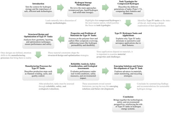
Figure 1.
Work structure, with main topic and connections.
This paper seeks to bridge that gap by meticulously selecting and discussing highly cited recent publications from prestigious journals. The analyses center on the latest advancements, which employ lightweight composite materials to contain hydrogen at high pressures. The review delves into innovative materials such as advanced carbon fiber composites that enhance tank resilience while minimizing weight. It also examines novel approaches to optimizing tank designs to improve thermal management during the compression process, a critical factor in maintaining structural integrity. Furthermore, the integration of advanced sensor technologies and IoT frameworks is discussed as a transformative approach to monitor tank integrity in real-time. These technological advancements are pivotal in enhancing safety protocols, allowing for preemptive maintenance and immediate response to potential hazards.
By synthesizing these key developments, the review serves to map the technological landscape of Type IV hydrogen storage systems, identifying cutting-edge research that pushes the boundaries of safety and energy efficiency. This comprehensive overview not only informs stakeholders of the latest advancements but also outlines a clear direction for future research aimed at addressing current limitations. This focused approach ensures that the paper serves as a critical resource for researchers and industry professionals aiming to innovate within this specific and strategically vital sector of hydrogen storage.
2. Hydrogen Storage Methodologies
Hydrogen storage technologies are typically divided into three categories: gaseous, liquid, and solid (Figure 2). Gaseous and liquid refer to the physical state of hydrogen, while solid refers to materials that store hydrogen by absorbing or binding it [29]. Each of these categories has specific characteristics that make them suitable for different operational needs. Each method has advantages and disadvantages that vary based on efficiency, costs, and specific applications [30]. The choice of the optimal method depends on the intended use, available infrastructure and operating conditions [31,32].
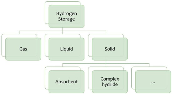
Figure 2.
H2 storage methods.
2.1. Gaseous Hydrogen Storage
Gaseous hydrogen storage is achieved by compressing the gas to high pressures, typically between 350 and 700 bar [33]. This method is widely used for both mobile and stationary applications, due to its relative technological simplicity and the widespread use of high-pressure tanks [14,34]. The main limitation of the gaseous method is its low energy density: hydrogen occupies a relatively large volume compared to other fuels, requiring the use of advanced tanks to increase efficiency [35].
Despite this limitation, the method is widely used for hydrogen transportation and distribution, especially in fuel-cell vehicles and stationary systems [36,37]. The tanks used to store gaseous hydrogen are made of advanced materials, such as carbon fibers and composites, to reduce weight and increase strength [38].
Specific technical details on gas tanks will be covered in the dedicated section.
2.2. Liquid Hydrogen Storage
Liquid hydrogen storage requires cooling the gas to −253 °C, allowing it to be stored in liquid form with a much higher energy density than the gaseous method [39]. The main advantage of this technology is the ability to store a larger amount of hydrogen in a smaller space, which is essential for large-scale industrial applications [40]. However, liquid storage presents some significant challenges, including the high cost of cryogenic infrastructure and the management of evaporation losses, which make the method less practical for mobile applications [41]. This method has been widely used in aerospace applications, such as space launches, where energy density is critical and the cost of infrastructure is justified by the nature of the application. In recent years, the industrial sector has developed more efficient systems for managing boil-off and energy losses, but liquid storage remains limited to industrial settings with high hydrogen consumption.
2.3. Solid Hydrogen Storage
Solid hydrogen storage relies on the use of materials such as metal hydrides or Metal–Organic Frameworks (MOFs), which can absorb and release hydrogen under controlled conditions of temperature and pressure [42]. This technology offers a safe method of storage, as hydrogen is trapped in a solid matrix, reducing the risk of leakage and minimizing the safety issues associated with other methods [24,43]. However, the storage capacity of these materials is still limited compared to gaseous or liquid technologies, and the rate of hydrogen release may not be fast enough for some applications [44]. Currently, solid storage is confined to specialized applications and experimental projects, but future prospects are promising thanks to the progress in research on new materials [45].
Some studies explore the nanocomposites and complex hydride use to improve the storage capacity and thermal management of systems [46,47]. In particular, nanocomposites based on lightweight materials such as magnesium, combined with expanded natural graphite particles, have shown an increased capacity to absorb hydrogen under optimal temperature and pressure conditions. Similarly, complex hydrides, such as sodium aluminate (NaAlH4) and lithium borohydride (LiBH4), present a high gravimetric density potential for hydrogen storage, despite requiring high temperatures and the use of catalysts for complete dehydrogenation [17,48,49].
A qualitative comparison of the main metrics of three hydrogen storage technologies is reported in Figure 2. In particular, compressed gas storage (700 bar), liquid hydrogen storage and Solid Metal Hydride storage are compared, through the observation of three different parameters: volumetric energy density (Figure 3a), the levelized cost (Figure 3b), the storage efficiency (Figure 3c). Each bar represents a normalized value with respect to the technology with the lowest performance, making it easy to compare the methods.
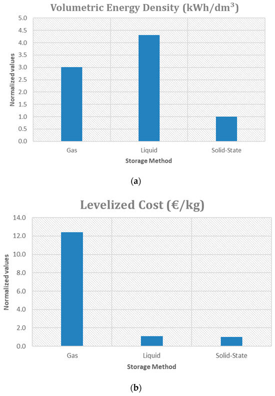
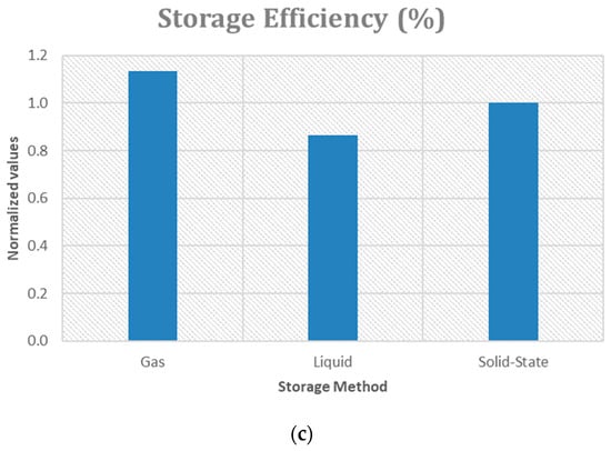
Figure 3.
Trends of the metrics compared: (a) Volumetric Energy Density; (b) Levelized Cost; (c) Storage Efficiency.
To effectively evaluate hydrogen storage, it is essential to consider its energy density relative to the entire storage system. While 1 kg of hydrogen possesses a high thermal energy content of approximately 120 MJ, a more accurate assessment must specify this energy relative to the weight of the storage vessel and its supporting components.
Each storage method involves distinct processes for accumulating hydrogen, which directly impact overall cost and efficiency. For example, compressed hydrogen is stored in tanks using compressors, liquid hydrogen is first liquefied at cryogenic temperatures and then pumped into insulated vessels, solid-state hydrogen (e.g., in metal hydrides) is absorbed into a metal lattice under moderate pressure.
This solid-state method is governed by physical kinetics, which requires careful thermal management. During the charging phase, heat must be removed (cooling), while during the releasing phase, heat must be supplied (heating). Consequently, in addition to mechanical energy input, this approach requires a thermal energy cycle, affecting its round-trip efficiency.
The gaseous storage method at high pressures stands out for interesting gravimetric density [50] (at 700 bar, 5.04 MJ/kg considering the entire structure), which is crucial for applications in the transport sector and hydrogen refueling stations [51]. However, it also has the highest levelized cost (12.68 euro/kg according to [52]). Despite the high cost, compressed gas maintains a high energy efficiency (about 85% [52]) and offers a volumetric energy density of about 5.6 MJ/dm3 [53], which does not reach the levels of liquid hydrogen (about 8 MJ/dm3 [54], 10.44 MJ/dm3 if cryo-stored [55]) but is still competitive. Liquid hydrogen is the cheapest option, slightly cheaper than salt cavern storage [56]. However, even with just a few days of storage, salt caverns become cheaper. LH2 storage for 14 days would cost 1.32 $/kg when liquefaction costs are included.
Liquid hydrogen storage is energy-intensive (~10 kWh/kg) and capital-intensive liquefaction process (~40–50% of capital expenditure of the liquid hydrogen storage system) [57]. However, its energy efficiency (65% [52]) is the lowest, due to the expensive liquefaction process. Liquid hydrogen is ideal where space is limited, but large quantities of hydrogen need to be stored. Solid Metal Hydride Storage has a high energy density when considering only the absorbing material (11.52–14.83 MJ/dm3) [58], but lower gravimetric density due to the additional weight of the overall structure (material, support, framework), falling in the range of 1.2 to 2.5 MJ/dm3. However, it offers high energy efficiency [52]. The low levelized cost (EUR 1.2/kgH2 for the onshore buffer storage [59]) and its volumetric energy density make it suitable for long-term storage applications, such as energy support for renewable energy systems [52]. Regarding the storage efficiency, a value of 70–80% can be considered [60].
Volumetric density is particularly important for projects that need to optimize space usage, such as storage infrastructure or long-distance transportation. Table 1 summarizes the main features of the storage methods, highlighting pros and cons.

Table 1.
Advantages and disadvantages for gaseous, liquid and solid hydrogen storage.
In conclusion, gaseous storage offers high performance in terms of gravimetric density and efficiency, but at high costs. Liquid Hydrogen is the most convenient in terms of cost and volumetric density, but with lower efficiency. Solid Storage balances cost and efficiency, but with a lower energy density, making it ideal for stationary applications.
Among the different storage methodologies discussed, compressed hydrogen remains the most widely adopted due to its relative maturity and practicality. To better understand its role, the next chapter examines the typologies of storage tanks specifically designed for compressed hydrogen.
3. Tank Typologies for the Gas Hydrogen Storage Based on Compression
The development of gaseous hydrogen storage tanks started in the early 20th century, when the first metallic tanks were used for the transportation and storage of high-pressure gas. With the second half of the century and the expansion of the energy industry, the first applications of hydrogen as an alternative fuel drove research into technologies that could reduce the tank weight without compromising safety [32,61]. In the 1970s, the global energy crisis further stimulated interest in hydrogen, leading to the development of composite tanks, which offered improved strength and reduced weight compared to all-metal [36,37,62].
Today, gaseous hydrogen storage tanks are classified into five main types (see Figure 4), each representing a significant technological evolution.
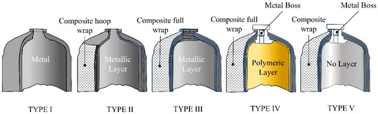
Figure 4.
Different Types of hydrogen tanks.
3.1. Type I: Full Metal Tanks
Type I tanks are the simplest and date back to the early uses of compressed gas. Made entirely of metal, such as steel or aluminum, they offer great strength and resistance to high pressures, but their heavy weight makes them impractical for mobile applications. They have been widely used in industrial plants, but as technologies have evolved, they have been progressively replaced in applications requiring greater efficiency and lightness [22]. However, in specific contexts such as stationary storage, Type I tanks remain a well-established choice. Type 1 tanks typically operate at 200–300 bar (2900–4350 psi), though some industrial variants may reach higher pressures. Primarily used for stationary storage (e.g., industrial hydrogen supply, laboratory gas storage) and low-mobility applications where weight is not critical, such as scuba tanks or bundled cylinder stacks for bulk delivery. Their robustness and lower cost make them ideal for high-volume, fixed installations.
3.2. Type II: Tanks with Metallic Layer and Composite Hoop Wrap
During the 1960s and 1970s, as materials technology improved, Type II tanks were developed, which combine a metal liner with partial windings of glass or carbon fibers [22]. This development was a step forward, reducing the overall weight of the tanks compared to Type I designs, while maintaining high mechanical strength. However, Type II tanks, despite the improvement, are still relatively heavy compared to more advanced types [63]. Type 2 tanks typically operate at 100–500 bar (1450–7250 psi), though most industrial designs cap at 300–350 bar for safety and cost efficiency. Today, these tanks have limited application in technologies that do not require extreme weight reduction, such as some fixed installations or the military [22]. Primarily used in industrial settings (e.g., gas storage) and limited mobile applications (e.g., backup power systems, some heavy-duty vehicles) where weight is less critical than cost. Their hybrid design balances durability and moderate weight savings compared to Type 1 tanks.
3.3. Type III: Tanks with Metallic Layer and Composite Full Wrap
In the 1990s, a breakthrough occurred with the introduction of Type III tanks. These tanks feature a metal liner, usually made of aluminum, completely wrapped in advanced composite materials, such as carbon fiber or aramid fiber [22]. This design allowed for a significant weight reduction compared to previous designs, increasing their efficiency, especially in mobile applications [64,65]. Type 3 tanks operate at pressures up to 700 bar (10,000 psi). Type III tanks have found widespread use in various sectors, including fuel-cell vehicles and some industrial applications. Their strength and light weight make them particularly suitable for applications where weight is a determining factor.
3.4. Type IV: Tanks with a Polymeric Layer and Composite Full Wrap
Type IV tanks, developed in the early 2000s, represent a further technological evolution. They use a fully polymer liner, usually made of high-density polyethylene (HDPE), which is completely wrapped in carbon fibers [66]. This approach has led to extremely light and highly resistant tanks, capable of holding hydrogen at high pressures, up to 700 bar. Type IV tanks are now the reference standard for fuel-cell vehicles and many other mobile applications, due to their lightweight and ability to ensure high levels of safety [67]. Some models are currently used in hydrogen buses and long-haul trucks. The thermal behavior during charging and discharging is another important aspect to be investigated, especially for fast cycles [68]. However, apart from this brief presentation, the whole paper is centered on Type IV tank technologies. Wider details are presented in the next sections.
3.5. Type V: Full Composite Tanks
Type V tanks represent the latest frontier in hydrogen storage technology development. These tanks do not use any internal liner, being entirely made of advanced composite materials [67]. Still under development, Type V tanks aim to offer the greatest weight reduction, even surpassing Type IV tanks, and may find future applications in the aerospace and long-distance transportation sectors. Preliminary tests suggest that, once fully engineered, these tanks will be able to offer superior performance at a significant reduction in operating costs [37].
Figure 5 compares the relative weight and cost per kilogram of hydrogen stored in Type I, II, III, IV, and V tanks. From the bar graph, it is clear that Type I tanks are the cheapest, but also the least efficient in terms of lightness. In contrast, Type IV tanks, thanks to the use of advanced composite materials, are 72% lighter than Type I tanks, at the expense of a 200% increase in cost [69]. This combination of reduced weight and cost makes them the optimal choice for many industrial applications. Type V tanks, although the lightest, are still in the experimental phase and cost 400% more than Type I [37], limiting their commercial diffusion. At present, Type IV remains the most popular solution to balance efficiency and costs.
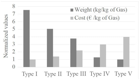
Figure 5.
Normalized weight and cost of tanks versus tank type.
4. Type IV Hydrogen Tanks and Their Applications
While the previous chapter outlined the main typologies of compressed hydrogen storage tanks, particular attention must be given to Type IV tanks, which represent the state-of-the-art solution.
Type IV hydrogen tanks, introduced in the early 2000s, are currently the most widely used in hydrogen mobility and energy storage applications, thanks to their ability to contain gas at high pressures, up to 700 bar, while maintaining a low weight. Their introduction has revolutionized the hydrogen storage sector, especially for applications in fuel-cell vehicles, where autonomy and lightness are key aspects [36,70]. Figure 6 displays the detailed design of a type IV tank, with its stratigraphy.
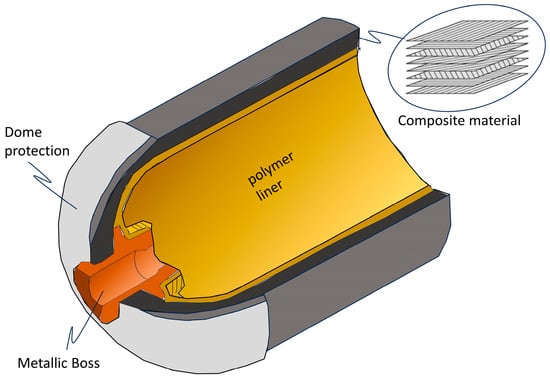
Figure 6.
Framework of a type IV tank.
4.1. Why Type IV Tanks?
The popularity of Type IV tanks has been driven by the need to store gaseous hydrogen for fuel-cell vehicles and energy storage applications. Since the 2010s, these tanks have become the preferred choice for vehicles such as the Toyota Mirai and Hyundai Nexo, thanks to their ability to store up to 5.7 kg of hydrogen in a 100 L tank at 700 bar, offering a range of over 500 km [71].
Type IV tanks are designed to maximize storage capacity while maintaining a low weight, improving efficiency and reducing long-term operating costs. They provide an optimal combination of safety, light weight and resistance to high pressures, contributing to the growing popularity of hydrogen vehicles worldwide [67].
4.2. Structure and Materials
Type IV tanks use two main components: the inner liner and outer shell.
- Inner liner. Made of high-density polymers such as HDPE (high-density polyethylene), it provides an effective barrier against hydrogen permeability. This material is chosen for its high chemical resistance and good mechanical properties, ensuring a long operational life [66,67]. Other polymers, such as polyamide (PA) and polypropylene (PP), can be used to optimize thermal resistance or reduce costs [72,73].
- Outer shell. Composed of carbon fibers impregnated with epoxy resin, the outer shell provides high mechanical resistance, capable of withstanding stresses of up to 2000 MPa. Carbon fibers also offer weight savings of up to 70% compared to metal tanks [74,75]. In some configurations, glass fibers or aramid fibers can be used to improve impact resistance or further reduce costs [76].
4.3. Geometry and Dimensions
Type IV tanks adopt cylindrical geometry with rounded ends, a choice that minimizes stress concentration, improving durability and resistance to high pressures. Figure 7 shows the stress distribution in a cylindrical tank at 700 bar, highlighting the ability of the design to evenly distribute stresses [77,78].
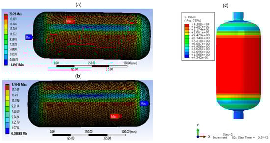
Figure 7.
Stress distribution on type IV tank: (a,b) at liner of a nominal working pressure of 70 MPa and temperature 15 °C [77], (c) static analysis regarding Mises stresses [78].
Tank sizes vary depending on the application [76,77,78,79].
- In light vehicles, such as cars, the most common tanks have a capacity between 50 and 150 L, with a diameter of 40–50 cm and a length of 0.8–1.2 m. A 100 L tank at 700 bar can store 5.7 kg of hydrogen.
- In heavy-duty vehicles, such as trucks and buses, tanks can reach a capacity of 300 L per single tank, with the adoption of modules to ensure autonomy of over 1000 km.
- For stationary storage, tanks can have a capacity of 500 L, with operating pressures ranging from 350 to 700 bar. They are often used in modular configurations to optimize storage capacity.
Regarding the tank structure, various scientific works report figures showing the internal and external structure of Type IV tanks. Feki et al. [74], for example, present a detailed cross-section that highlights the internal polymer liner and the external carbon fiber layers that form the shell. Other studies, instead, are intended to illustrate figures that show the stress distribution in the tank at high pressures, as well as the strain profiles demonstrating the effectiveness. In this regard, Figure 8 displays the strain distributions along the fiber path for both hoop layers (top curves) and helical layers (bottom curves) in the baseline tank. In the cylindrical section (represented by straight horizontal lines in Figure 8), each layer exhibits uniform strain along the fiber direction. The strain magnitude is greatest in the innermost hoop layer and progressively decreases toward the outer layers. Additionally, due to the lower axial stress compared to hoop stress in pressure vessels, helical layers experience reduced strain relative to hoop layers. In the dome region, the strain becomes non-uniform, increasing with proximity to the boss.
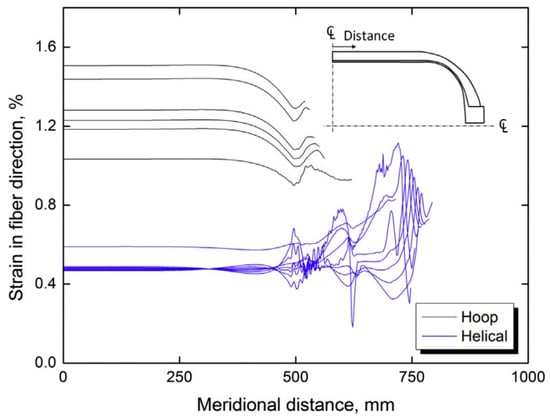
Figure 8.
Strain profiles in a 147 L baseline tank [50].
4.4. Applications
Type IV tanks are mainly used in fuel-cell vehicles, where their lightness and ability to store hydrogen at 700 bar allow for high autonomy and rapid refueling times of less than 5 min. Table 2 shows a technical and energy comparison between hydrogen-fuel-cell vehicles with type IV tanks with battery electric and traditional vehicles, highlighting the efficiency together with the main technical parameters [80].
Table 2.
Characteristics comparison of ICEVs, fuel-cell electric vehicles (FCEVs) and BEVs [80].
In the heavy transport sector, such as buses and trucks, type IV tanks are used to ensure greater storage capacity without compromising the available space. These tanks are arranged in modules to optimize space and facilitate maintenance [81].
Even in stationary applications, type IV tanks play a crucial role in enabling the storage of hydrogen produced from renewable sources [81]. In such plants, hydrogen is stored to be later converted into electricity via fuel cells, contributing to the stabilization of the energy grid [7]. Some configurations are designed to bring hydrogen safely and efficiently to the point of need [82].
The diverse applications of Type IV hydrogen tanks rely heavily on the performance of their constituent materials. Therefore, it is fundamental to examine the properties and challenges of these materials, which are critical to ensuring both safety and efficiency.
5. Properties and Problems of Materials for Type IV Tanks
Type IV hydrogen tanks represent an advanced solution for high-pressure gas storage, combining lightweight design with high performance. Their construction relies on a polymeric liner, which ensures hydrogen containment, and a composite overwrap, typically made of carbon fibers, which provides the required mechanical strength. Despite their advantages, the use of Type IV tanks introduces a set of challenges, concerning hydrogen permeability, blistering, structural strength-adhesion and thermal effects.
5.1. Permeability
Permeability in Type IV tanks is a key issue due to the tendency of extremely small and lightweight hydrogen molecules to diffuse through the polymer materials used in the liners. This phenomenon can lead to several significant issues, including gas leakage, reduced tank efficiency, and potential damage to composite materials over time.
Permeability management is essential to ensure the safety and durability of Type IV reservoirs [83].
5.1.1. Physical Laws That Govern Permeability
The permeation process in polymeric materials is described by Fick’s first law (Equation (1)), which governs the diffusion flow of a gas through a solid, is shown in Equation (1), where is the flux of hydrogen molecules (moles per unit area per unit time), D is the diffusion coefficient of the material, which varies with temperature and polymer composition and represents the concentration gradient of hydrogen through the thickness of the liner [84].
Permeation occurs in three stages [83]:
- Adsorption: Hydrogen molecules are absorbed by the inner surface of the liner.
- Diffusion: Molecules move through the polymer matrix.
- Desorption: Hydrogen is released from the outer surface of the liner [85].
Increasing the temperature accelerates the rate of permeation, as described by the Arrhenius equation, reported in Equation (2), where D0 is the pre-exponential diffusion coefficient, Ea is the activation energy for diffusion, R is the gas constant and T is the absolute temperature [61].
The permeation rate is influenced by two key factors: the diffusion coefficient (D) and the solubility coefficient (S) of the gas in the polymer. The total permeability (P) of a material can be expressed as shown in Equation (3) [86].
Denser materials, such as polyamide 6 (PA6), generally have lower permeability than high-density polyethylene (HDPE), due to lower diffusion and solubility values [32].
It should be underlined that PA6 is one of the most promising materials for Type IV tank liners due to its density and good barrier properties, which reduce the rate of hydrogen permeation. PA6, or nylon-6, is a widely used material in Type IV hydrogen storage tanks, serving as a liner material. While PA6 offers advantages like good mechanical strength and resistance to gas permeation, it also has limitations like relatively high hydrogen permeability and low-temperature toughness, which can affect the long-term performance and safety of hydrogen storage tanks [87].
Recent studies have shown that the integration of multiple layers and chemical modifications to the polymers can further improve the permeability resistance [88,89]. For example, Dong et al., in [87], examined the hydrogen permeability through PA6, showing that modifying the operating parameters, such as pressure and temperature, can have a significant impact on the diffusion of hydrogen molecules.
5.1.2. Problems Arising from High Permeability
High permeability can cause several operational and durability issues, such as hydrogen leakage and reduced efficiency, compromised tank durability and influence on mechanical behavior [83,87].
- Hydrogen leakage and reduced efficiency. Continuous leakage of hydrogen through the liner can significantly reduce the amount of gas available and, consequently, the operational efficiency of the tank. This issue is particularly critical in mobile applications, where the amount of hydrogen stored determines the range of the vehicle. In stationary applications, hydrogen leakage increases operating costs [31].
- Compromised tank durability. Hydrogen leaking through the liner can reach the composite shell and degrade the mechanical properties of the carbon fibers or epoxy resin, compromising the structural strength of the tank in the long term.
- Influence on mechanical behavior. Prolonged exposure to hydrogen can lead to embrittlement of the composite shell. The accumulation of microcracks and gas pockets can reduce the ability of the vessel to withstand high pressures, resulting in a risk of failure during repeated load cycles.
5.1.3. Strategies to Reduce Permeability
Several strategies have been developed to mitigate permeability issues, e.g., multilayer composites, nanomaterial integration and chemical modifications of polymers [90,91].
- Multilayer composites. The use of multilayer liners that combine different polymers with different barrier properties is an effective solution. Each layer provides an additional barrier, forcing hydrogen molecules to travel a longer path and reducing the overall permeability [91].
- Nanomaterial integration. The addition of graphene or graphene oxide nanoparticles to polymer liners creates a tortuous path that hinders the movement of hydrogen molecules, reducing the permeation rate. This technique offers significant benefits without increasing the weight of the tank [91].
- Chemical modifications of polymers. Modifying the molecular structure of polymers, such as by cross-linking or adding additives, can reduce hydrogen solubility and improve barrier properties without compromising the mechanical properties of the material [91].
5.1.4. Other Relevant Aspects
Other relevant aspects concern temperature and pressure variations, external agents and real-time monitoring.
- Effects of variable temperature and pressure. Recent studies have highlighted that those dynamic variations in temperature and pressure, typical of loading and unloading operations, can accelerate permeation processes and must be managed with thermal control technologies [62].
- Effects of external agents. UV radiation and chemicals present in the environment can accelerate the degradation of polymeric liners, increasing permeability over time [92].
- Real-time monitoring. Emerging technologies such as real-time hydrogen leakage monitoring sensors are proving to be crucial to prevent tank degradation and improve operational safety [93].
Currently, onboard hydrogen storage tanks operate within a temperature range of 233 K (−40 °C) to 358 K (85 °C) [94], making it crucial to investigate hydrogen permeation behavior under these conditions. Experimental results (Figure 9) demonstrate that among all tested materials, polyamides and polyethylene exhibit superior gas barrier properties. Furthermore, the hydrogen permeability coefficient of these materials follows Arrhenius’ law, showing a consistent increase with rising temperature. Figure 9b demonstrates that the gas permeation rate per unit mass of ultra-high molecular weight polyethylene (UHMWPE) increases with rising test pressure, though the rate of increase gradually diminishes. The divergence between the experimental data and the theoretical dotted line indicates that at elevated pressures, the gas permeation process deviates from Henry’s law, which predicts a linear relationship between dissolved gas concentration in the polymer matrix and external partial pressure.
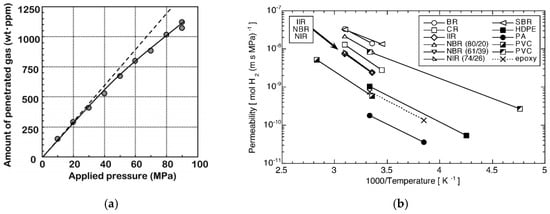
Figure 9.
(a) Pressure dependence on hydrogen permeability (dashed line represents the theoretical Herny’s law, continuous line with dots indicates experimental measurements), (b) temperature dependence of hydrogen permeability of various polymer materials [83].
5.2. Blistering
Blistering, or gas cavity formation, is a major concern in polymeric Type IV tank liners. This phenomenon occurs when hydrogen, having penetrated the material, becomes trapped during pressure and decompression cycles, generating internal stresses in the form of gas pockets [95]. Over time, these gas cavities can expand, compromising the mechanical integrity of the tank and reducing its operational safety [96].
5.2.1. Causes of Blistering
Blistering is mainly triggered by rapid decompression cycles, which prevent hydrogen from diffusing uniformly from the liner to the outside. When gas remains trapped inside the polymer material, gas pockets form, which cause increasing internal pressure [97]. Experimental studies have shown that rapid decompression cycles limit the uniform release of gas, leading to dangerous accumulations of hydrogen in the polymer matrix [82]. Less dense materials, such as high-density polyethylene (HDPE), are more prone to this phenomenon, compared to more crystalline polymers such as polyamide 6 (PA6), which offers a more effective barrier against hydrogen diffusion [24].
The composition of the liner plays a crucial role in the propensity for blistering. More crystalline polymers, such as PA6, and advanced materials such as polyether ether ketone (PEEK) and polyamide-imide (PAI), are less susceptible to the formation of gas cavities due to their compact and rigid structure, which limits the diffusion of hydrogen [83,86,91].
5.2.2. Blistering Mechanism
The mechanism underlying blistering is related to the internal pressure generated by the gas trapped inside the liner. When hydrogen molecules cannot fully diffuse out of the liner, they form gas pockets that, expanding, deform the polymer material. This process, in addition to generating gas cavities, can lead to the delamination of the liner from the composite shell, compromising the adhesion and structural integrity of the tank [56,98].
Tests conducted on rapid decompressions have shown that the accumulation of gas inside the microstructures of the liner not only favors the formation of cavities but also accelerates the formation of microcracks [99]. These cracks can propagate over time, increasing the risk of structural failure under repeated pressure cycles.
5.2.3. Consequences of Blistering
Gas cavities that form within the liner progressively compromise the integrity of the tank, promoting the loss of adhesion between the liner and the composite shell [100]. This deterioration compromises the ability of the tank to maintain high operating pressures, reducing safety during use. Furthermore, the presence of cavities accelerates crack propagation, a phenomenon particularly common in materials such as HDPE, where gas entrapment is more frequent [84]. These cracks propagate under repeated pressure cycles, causing potential mechanical failure of the tank.
5.2.4. Interaction with Hydrogen Fragilization
A crucial aspect that has recently emerged is the combination of blistering with hydrogen embrittlement. Blistering, combined with embrittlement, accelerates the mechanical degradation of the reservoir, further compromising the material’s ability to withstand cyclic stresses and high pressures [101].
5.2.5. Effects of Rapid Charging Cycles
Another cause that can exacerbate blistering is the use of rapid refill cycles. When hydrogen is refilled quickly, the molecules do not have enough time to diffuse evenly, increasing the risk of cavities forming within the liner. This phenomenon becomes more pronounced in high-temperature operating environments, where the gas tends to diffuse more rapidly [102,103].
5.2.6. More Resistant Polymers
Materials with a more compact crystalline structure, such as PA6, offer greater resistance to hydrogen permeation and, consequently, reduce the risk of blistering. PA6 limits the diffusion of hydrogen, preventing the formation of gas pockets. Materials such as PEEK and PAI, due to their crystalline structure and excellent mechanical and thermal properties, are also less prone to the formation of gas cavities. The integration of nanocomposites, such as graphene or montmorillonite clays, within polymers can further improve the resistance to permeation, creating a physical barrier that slows the diffusion of hydrogen [86,87].
5.2.7. Strategies to Mitigate Blistering
To reduce the risk of blistering, several strategies have been developed.
- Use of more resistant materials. The adoption of highly crystalline polymers, such as PA6, PEEK and PAI, together with nanocomposites, improves permeation resistance and reduces the risk of gas cavity formation [31].
- Optimization of pressure cycles. More gradual decompression cycles allow hydrogen to diffuse slowly, preventing the accumulation of trapped gas. Experimental tests have shown that slower decompression significantly reduces the risk of blistering [61].
- Multilayer liners. The use of multilayer liners, which combine materials with different barrier properties, reduces hydrogen permeation and, consequently, the risk of blistering. Multilayer structures act as physical barriers that hinder the diffusion of gas [67].
- Production Control. Improving liner manufacturing processes to eliminate defects such as inhomogeneities or inclusions reduces the risk of blistering. A controlled manufacturing process ensures greater uniformity of the material, decreasing gas accumulation points.
- Control of Operating Temperatures. Temperature control during refill cycles is crucial. Rapid refills and high temperatures increase the risk of blistering, therefore it is essential to implement strict thermal control during tank operation [103].
In conclusion, blistering is a complex challenge in Type IV tanks, but advances in materials, manufacturing processes and management of operating conditions offer promising solutions to reduce the risk and improve tank durability. The adoption of nanocomposites, multilayer structures and optimization of manufacturing processes are the most important steps towards increased resistance and operational safety of Type IV tanks.
5.2.8. Detection and Control Technologies
An emerging area of research involves the use of advanced sensors to monitor gas buildup and cavity formation in real time within the liner. These technologies can detect blistering before it compromises tank safety, providing an innovative method to monitor and manage operating conditions more safely [93].
Figure 10 illustrates the temperature-dependent cavitation risk in HDPE liners during gas decompression. This process involves two competing mechanisms [104]: (1) a depressurization effect, where rapid pressure reduction cools both the gas and liner material, and (2) a heat transfer effect, where ambient temperature gradually reheats the liner (which cools below environmental temperatures during emptying).
Polymeric materials exhibit strong temperature sensitivity. For PA6 [105], PA11 [96,106] and HDPE [107], increasing temperatures reduce both Young’s modulus and yield stress. This thermal softening lowers the critical stress threshold required for material failure when subjected to internal gas pressure.
Melnichuk et al. [108] quantified these relationships by modeling hydrogen diffusivity coefficients and yield strength of HDPE as functions of temperature using literature data. Their results revealed opposing trends: while hydrogen diffusivity increased with temperature, the material’s yield strength decreased.

Figure 10.
Cavitation risk at different temperatures [108].
The decompression rate is a critical parameter for compressed hydrogen tanks, defined as the rate of high-pressure gas release (typically in MPa/min) [86]. This parameter directly influences the gas concentration gradient within polymer liners following decompression, consequently affecting both the magnitude and distribution of residual stress.
For Type IV tank liners, Yersak et al. [109] conducted a systematic investigation comparing HDPE and PA specimens subjected to decompression periods of 1, 3, 5, and 13 h. Figure 11 shows that the central white regions in cross-sections represent decompression-induced blistering and both blister area and density exhibit progressive reduction with extended decompression time. These findings demonstrate an inverse relationship between decompression duration (rate) and material damage severity.
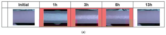
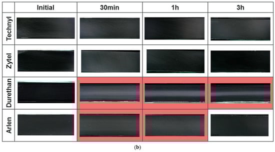
Figure 11.
Cross-section of HDPE liner before and after hydrogen decompression (a); cross-section of PA liners before and after hydrogen decompression (b). The red areas concern events when blistering occurs [109].
Complementary studies on various PA formulations revealed significant brand-dependent behavior [109]. Although certain samples displayed minimal or no blistering, others exhibited varying blister severity. This variability suggests material-specific differences in hydrogen diffusivity, where higher diffusion coefficients correlate with reduced cavitation risk through more efficient gas egress [110].
5.3. Structural Strength and Adhesion
Structural strength and adhesion in Type IV hydrogen storage tanks are critical to ensure safety and optimum performance under high pressures. These tanks, which consist of a polyethylene or polyamide liner reinforced with carbon fiber composite layers, face significant challenges in managing mechanical stress and maintaining structural integrity over time [66].
To further improve the adhesion between the liner and the composite shell, Schäkel et al. [111] propose the use of pre-impregnated tapes to wrap the liner in a controlled manner, reducing void formation and improving the overall quality of the shell.
5.3.1. Structural Strength
The structural strength of Type IV tanks depends largely on the materials used. For example, Kevlar fiber has a lower maximum strain than T700 carbon fiber or S-glass, making it suitable for applications requiring minimal deformations [44]. However, under high loads, sudden failures may occur due to exceeding the maximum material strength or the propagation of microcracks. Defects such as voids and imperfections in the composite can facilitate crack propagation into more severe fractures, compromising the integrity of the tank [97].
Progressive failure of the structure under repeated loading cycles is another relevant failure mechanism in Type IV tanks. Interlaminar voids and winding defects cause uneven stress distributions, increasing the risk of local failures, especially in critical areas such as transitions between the cylinder and the tank domes [66]. Mechanical fatigue in these areas can cause crack propagation, which, over time, can lead to catastrophic failures [98].
5.3.2. Fatigue Breaks
Fatigue is a major cause of failure in Type IV tanks, especially in applications involving repeated pressurization and depressurization cycles. During these cycles, microcracks tend to develop in composite materials, often originating from interlaminar voids or defective areas [44]. Cracks propagate in the transition zones between the cylinder and the dome, where the stress distribution is less uniform [91]. Voids in the composite act as trigger points for crack growth, causing progressive weakening of the structure [97].
Crack propagation can be accelerated by increasing the number of load cycles, making fatigue a critical factor for tank durability [87]. Experimental studies have shown that fatigue failure tends to occur mainly in areas subjected to high-pressure cycles and thermal variations [112]. In this field, the oxidation of the linear material, due to thermal effects, directly affects the fatigue performance of hydrogen tanks. Among the main studies, Alexis et al. investigated the fatigue lifetime of short glass fiber reinforced thermoplastics (35% and 50% fiber) under thermal aging (500 h at 200 °C). Aging caused matrix stiffening and embrittlement, more pronounced in the lower-fiber material, but initiation-based fatigue prediction remained valid. Cyclic creep energy-based criteria effectively predicted fatigue for both unaged and aged composites [113].
5.3.3. Thermal and Thermo-Mechanical Effects
In addition to mechanical fatigue, thermal cycling plays an important role in the structural strength of Type IV tanks. Temperature variations, such as those generated during rapid refueling or due to the external environment, can cause thermal stress that lead to delamination phenomena or embrittlement of the materials. Accumulated thermo-mechanical stresses can accelerate liner failure or delamination between the liner and the composite shell, reducing the useful life of the tank [62].
5.3.4. Creep Phenomena
Creep, or progressive deformation under constant loads, is a phenomenon that mainly affects polymeric liners, such as polyethylene [86,114]. Under high and prolonged pressures, the liner can become thinner, reducing its ability to support the composite liner. This process is particularly evident during long-term storage, where the liner is subjected to constant pressures. Progressive deformation reduces the stability of the tank, increasing the vulnerability to cracking and amplifying the effects of mechanical fatigue.
To reduce the risk of creep, polymers with greater resistance to this phenomenon are used, such as modified high-density polyethylene or reinforced polyamides. Careful control of manufacturing parameters, such as temperature and cure times, is essential to prevent permanent deformations in the liner.
5.3.5. Adhesion
Adhesion between the inner liner and the outer composite layer is critical to maintain the structural integrity of the tank [115]. Under cyclic loading conditions, poor adhesion can lead to delaminations, reducing the overall strength and increasing the risk of failure [63]. The introduction of graphene nanoparticles into the liners is a promising strategy to improve adhesion, reducing the risk of separation between the layers [115].
Delaminations tend to propagate rapidly under high loads, resulting in a loss of structural integrity. Blistering can also get worse than this phenomenon, especially under rapid pressurization and depressurization cycles [100]. Poor adhesion between the liner and the composite compromises the tank’s ability to maintain high operating pressures, increasing the risk of failure.
5.3.6. Monitoring and Advanced Techniques
An area of growing interest is the real-time monitoring of the structural conditions of tanks through the use of advanced sensors. These sensors, integrated into the liner or composite shell, allow the detection of micro-fractures, delaminations and changes in mechanical resistance during use. The adoption of such technologies can increase operational safety and allow predictive maintenance, preventing sudden failures [24].
5.3.7. Prevention and Improvement Strategies
To ensure the safety and durability of Type IV tanks, careful management of structural strength and adhesion is essential [66,116]. The use of high-performance materials, such as Kevlar, provides superior mechanical strength, but equally important is preventing manufacturing defects and optimizing interactions between the liner and the composite shell [44]. Additionally, the use of multilayer liners, which combine materials with different mechanical and barrier properties, can reduce the risk of crack propagation and improve the operational life of the tank. Strict control of manufacturing processes is also crucial to prevent structural defects [117].
Figure 12 displays the matrix cracking. Matrix cracking initiation typically occurs during the initial loading phase, particularly in off-axis plies subjected to elevated transverse stresses. These cracks predominantly develop perpendicular to fiber orientation and propagate through the laminate thickness. Serving as precursors to delamination, matrix cracks significantly compromise the composite’s structural integrity through two primary mechanisms: (1) by reducing effective load-bearing capacity and (2) by generating localized stress concentrations that promote secondary failure modes, including fiber-matrix interface debonding and interlaminar shear failure.
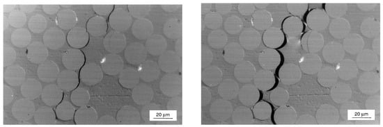
Figure 12.
Propagation of matrix cracking at the microscopic scale [118].
Figure 13 presents the progressive damage evolution in periodically loaded unidirectional cross-ply composites, showing three distinct failure stages: (1) matrix cracking initiation, (2) fiber-matrix interface debonding, and (3) fiber fracture. The damage progression correlates directly with fatigue life and exhibits three characteristic phases:
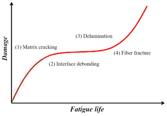
Figure 13.
General damage process of a laminate under quasi-static, tensile-tensile fatigue loading.
- Initial Phase: Rapid damage accumulation marked by matrix microcrack formation and propagation along off-axis fiber directions under tensile stresses.
- Intermediate Phase: Stabilized damage growth where matrix crack density increases progressively across multiple plies until reaching the Characteristic Damage State (CDS)—a saturation point where crack spacing stabilizes due to stress redistribution.
- Final Phase: Accelerated damage accumulation featuring:
- ○
- Delamination initiation driven by interlaminar stress concentrations (free-edge effects)
- ○
- Synergistic interaction between existing matrix cracks and fiber fractures
- ○
- Progressive delamination propagation under continued cyclic loading
This sequential damage mechanism ultimately leads to structural failure of the composite system.
5.4. Thermal Effects in Refueling Processes
Rapid refueling of Type IV hydrogen tanks, operating at high pressures (up to 70 MPa), presents a significant thermal challenge due to the inverse Joule-Thomson effect. This phenomenon, which causes a rapid increase in the internal temperature of the tank, can increase the gas temperature to over 85 °C [119,120]. This thermal increase poses a threat to the integrity of the polymer liner and the composite layer, increasing the risk of degradation phenomena, such as blistering, delamination and thermo-mechanical fatigue. Effective management of this phenomenon is crucial to ensure operational safety and tank longevity.
5.4.1. Heat Distribution and Thermal Challenges
One of the most important aspects of rapid refueling is the non-uniform distribution of heat within the tank. CFD simulations have shown that domes and transition zones between cylinders and domes are subject to greater heat accumulation than other areas of the tank [19,22]. This phenomenon is due to the geometry of the tank and the variation in material properties along its structure, making these areas more vulnerable to thermal failure. Heat management in these areas is of primary importance to avoid structural problems, which can be aggravated by the use of materials with suboptimal thermal properties or by designs that do not distribute thermal stress correctly.
A key factor in controlling internal temperature is the filling speed. The use of pre-cooled hydrogen during refueling has been shown to be an effective mitigation strategy, limiting the temperature increase and associated stress on the polymer liner [119,120]. However, even with pre-cooling, thermal differences within the tank persist, especially in critical zones. Optimized tank design, combined with advanced heat management techniques, can improve heat distribution and reduce the risks associated with these thermal gradients.
5.4.2. Thermal Effects on Materials and Degradation
Rapid temperature increases during refueling not only compromise the liner and composite shell of the tank but also affect the materials in more complex ways. Repeated thermal cycling during refueling accelerates the aging process of the materials, reducing the ability of the liner to maintain its mechanical integrity. Saferna et al. [121] highlighted how continuous exposure to thermal cycling leads to a reduction in the mechanical strength of the polymer liner and progressive deterioration of the composite layer.
In addition, the interfaces between the liner and the composite shell are particularly vulnerable to thermal differentials. In these areas, differential thermal expansion can cause delamination, increasing the risk of structural failure. Delamination is a major cause of failure in Type IV tanks, especially in critical areas, e.g., transitions between different geometric sections [19,22].
5.4.3. Interaction with Blistering and Hydrogen Fragilization Phenomena
In addition to aging and delamination issues, increasing the temperature during refueling can exacerbate blistering, where pockets of hydrogen become trapped in the polymer liner [100,109]. As the temperature increases, these pockets expand, causing additional internal stresses that accelerate material deterioration. The combination of thermal and mechanical stresses can make the liner more vulnerable to microfractures and cracks, which in turn compromise the tightness of the tank.
Another critical issue to consider is hydrogen embrittlement [122], where hydrogen diffuses into the tank materials, reducing their ductility and increasing the risk of fractures. Increasing the temperature during refueling can facilitate the diffusion of hydrogen into the materials, accelerating the embrittlement process. Recent studies suggest that the use of protective coatings and hydrogen-resistant materials, such as nanocomposites, may provide additional protection against this phenomenon.
5.4.4. Mitigation Solutions and Strategies
To mitigate thermal effects and reduce the risk of structural deterioration [114,123,124], several technological solutions have been developed. One of the main strategies is the integration of advanced temperature sensors and active cooling systems. These systems allow for monitoring in real time the internal temperature of the tank and regulating the hydrogen flow during refueling to avoid the temperature exceeding the safety limits [125]. Active cooling is particularly effective in reducing temperature peaks in critical areas, protecting the liner and the composite from cumulative damage.
In addition to thermal control systems, the use of innovative materials is essential to improve resistance to thermal cycling. Advanced polymeric materials, combined with nanocomposites and multilayer structures, offer additional protection against hydrogen permeation and blistering. These materials are designed to reduce hydrogen diffusion and minimize internal stress due to thermal cycling [68,103]. Furthermore, thermo-mechanical simulations during the tank design phase can help identify weak points and prevent failures due to uneven heat distribution.
Another important aspect is the management of refueling times. If tanks are refueled too frequently without adequate cooling between cycles, residual heat can build up, causing cumulative thermal damage. Proper management of refueling times, together with the use of pre-cooled gas and active cooling systems, can extend the operational life of the tank.
Figure 14 presents a comparative analysis of filling strategies (at 70 MPa) for Type IV hydrogen storage cylinders. The study evaluates six distinct inlet pressure rise profiles. Specific test conditions for a 24 L cylinder include:
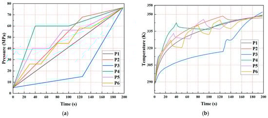
Figure 14.
(a) Inlet pressure rise patterns for the cylinders; (b) evolutions of the hydrogen temperature rise [126].
- Constant hydrogen inlet temperature: 233 K (−40 °C)
- Varied filling parameters: Cases P1–P6 (detailed in Table 3)
Table 3. Parameters for filling case study [126].
This experimental configuration enables systematic evaluation of temperature and pressure effects on filling performance.
The study examines six distinct pressure rise profiles during hydrogen filling:
- Linear pressure rise (P1);
- Fast–slow linear pressure rise (P2);
- Slow–fast linear pressure rise (P3);
- Single 60 s pressure hold (P4);
- Two 30 s pressure holds (P5);
- Three 20 s pressure holds (P6).
Figure 14a illustrates the pressure changes during filling, while Figure 14b demonstrates the temperature evolution for each pressure profile. Concerning the temperature-pressure relationship, maximum temperature rise varies significantly with pressure profile (P3: 352 K; others: 348–349 K), resulting in state-of-charge (SOC) variations from 94.5% to 95.2%.
Under baseline conditions (namely 198 s fill time, 233 K hydrogen, 288 K ambient), all profiles maintain a maximum temperature lower than 358 K. However, elevated ambient temperatures combined with rapid pressure rise may exceed 358 K; this can require higher flow rate capacity in hydrogenation equipment and voidance of aggressive pressure rise rates.
Table 4 shows a summary description with c0nsiderations on phenomena, main problems and challenges of Type IV tank materials.
Table 4.
Summary considerations on properties and problems of Type IV tank materials.
6. Structural Design and Optimization of Type IV Hydrogen Tanks
The limitations and challenges of materials used in Type IV tanks directly shape their structural design and optimization strategies. Building on the material considerations discussed, it is necessary to explore how design approaches and optimization techniques address these constraints.
Type IV hydrogen tanks are designed to balance lightweight and structural strength, which are crucial in both automotive and stationary applications, where hydrogen needs to be stored at high pressures. The optimal design of these tanks involves careful material selection, well-studied geometry and the use of innovative processes, with the aim of maximizing mechanical performance while reducing weight and production costs. The combination of these strategies ensures operational safety and durability even in extreme conditions. For instance, among the main works in this area, Park et al., in [89], studied the design of the composite layer and liner, introducing the use of isotensoid curves to improve the stress distribution, especially in critical areas such as tank domes. By optimizing the shape and thickness of the liner and outer shell, a balance between storage capacity and low weight can be achieved, ensuring operational safety even at high pressures.
The use of advanced materials is a key point in the design of Type IV tanks. The outer shell of these tanks is typically reinforced with carbon fibers, known for their high elastic modulus and ability to withstand high stress. Studies have shown that the use of carbon fibers with an elastic modulus of 288.8 GPa can significantly reduce the risk of mechanical failure by ensuring uniform stress distribution, which in helical fibers can reach values up to 84 MPa [85]. Efficient material management, particularly in the arrangement and lay-up of fibers, is essential to balance weight reduction with structural strength. Optimal lay-up has been shown to reduce weight without compromising the ability to withstand high pressures [62].
The geometric design of Type IV tanks plays a crucial role in the internal stress distribution. Tanks with cylindrical configurations and hemispherical domes are particularly suitable for optimizing the pressure distribution, minimizing high stress points. Finite element analysis (FEA) has shown that the transition areas between the cylinder and the domes are critical in terms of stress concentration, requiring careful considerations of the composite thickness in these areas to avoid structural failure [73].
Recent studies have reported that optimizing the composite shell thickness can improve pressure resistance without increasing weight. Increased burst pressures of up to 157 MPa have been observed in optimized tanks using thin but strong composite layers, reducing overall weight without compromising safety [28,73]. Such optimizations, based on FEA simulations, allow to identify weak points of the tank and optimize the material distribution, improving overall performance.
In addition to internal stress resistance, Type IV tanks must provide high resistance to impacts and punctures. This is particularly important for automotive applications, where tanks may be subject to impacts or collisions. Recent studies have shown that the integration of protective layers can improve the tank’s ability to withstand impacts, reducing the risk of catastrophic failure [21,40,63].
Along with the impact resistance, dynamic hydrogen permeability through polymer liners is a crucial factor to consider. While permeability at static pressures has been studied, real-world operating conditions involve pressure and temperature cycling, which can increase the risk of hydrogen permeation [95,97,127]. Recent studies have investigated dynamic permeability, showing that the use of multilayer barriers and nanocomposites can significantly reduce hydrogen permeation during prolonged use under varying conditions [63,80].
While structural design and optimization establish the theoretical framework for achieving safe and efficient Type IV tanks, their practical implementation depends on appropriate manufacturing processes. For these reasons, the next chapter examines the production methods that lead optimized designs to reliable tanks.
7. Type IV Tank Manufacturing Processes
Type IV hydrogen tanks represent one of the most advanced solutions for the safe storage of hydrogen at high pressures. The manufacturing process involves advanced techniques that combine polymer materials for the liner and carbon fiber composites for the outer shell, with particular attention to the integration of components such as the metal boss. To ensure reliability, safety and resistance, manufacturing processes must be highly automated and optimized, minimizing defects and maximizing the quality of Type IV tanks.
7.1. Composite Shell Production
Composite shell manufacturing is one of the main methods for manufacturing Type IV tanks. This process involves winding of resin-impregnated carbon fibers around the polymer liner using computer numerical control (CNC) machines. CNC machines adjust the fiber tension, winding speed and fiber layout, ensuring precise stress distribution and reducing the possibility of defects such as voids and misalignments [99]. Fibers can be arranged in circular and helical configurations, providing resistance to both radial and longitudinal loads.
Multiaxial winding configurations, shown in Figure 15, are an advanced technology that can further improve stress distribution, especially in the transition areas between the cylinder and the tank domes, reducing critical stress points and improving tank durability [75,111]. Furthermore, optimizing the fiber tension during winding is essential to ensure uniform resin impregnation and reduce the risk of structural defects [128].
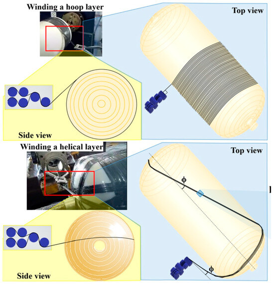
Figure 15.
Winding technique for hydrogen tank [75].
Among the shell production techniques, Schäkel et al., in [111], explored the benefits of the laser-assisted helical winding process, which allows for the control of the composite consolidation temperature during the manufacturing phase. This method reduces structural defects and improves process efficiency, making it ideal for the mass production of high-performance tanks.
7.2. Polymer Liner Production
A polymer liner is essential to prevent hydrogen permeation. It is produced through rotational molding or extrusion techniques, both of which create uniform thicknesses and reduce defects [129]. Precise temperature control during molding or extrusion is crucial to maintain the mechanical and chemical properties needed to prevent gas leakage [100].
Recently, the integration of nanocomposites, such as graphene nanoparticles, into polymer liners has significantly improved permeation resistance, reducing blistering and extending the operational lifetime of tanks [45]. The use of these nanocomposites in liners has been shown to reduce hydrogen leakage and improve long-term durability, which is particularly relevant for mobile and stationary applications that require repeated pressurization cycles.
7.3. Sealing the Metal Boss
The metal boss, responsible for connecting the tank to the gas filling and exhaust systems, is a critical component that requires perfect sealing. Multi-layer sealing and the use of advanced adhesive materials improve the integration between the boss and the polymer liner, ensuring a hermetic seal even after numerous pressurization cycles. The quality of the seal is essential to prevent leaks and ensure that the tank maintains its structural integrity. The use of advanced coatings and adhesive materials, that can withstand thermal and mechanical stresses, reduces the risk of separation between the boss and the liner, maintaining the seal even in extreme operating conditions [89,130].
7.4. Post-Process Control and Maintenance Techniques
The integration of nondestructive testing (NDT) techniques, such as ultrasound and computed tomography (CT), allows the detection of internal defects such as voids, fiber misalignments or abnormal thicknesses, reducing the risk of hidden defects that could compromise operational safety. In addition, the integration of real-time sensors during manufacturing permits the monitoring and control of critical parameters, ensuring that each tank meets quality standards before entering service. Advanced monitoring systems can detect microcracks or defects at an early stage, allowing for timely corrective action [116]. An experimental test bench, reporting the acoustic emission sensors on a hydrogen tank, is reported in Figure 16.
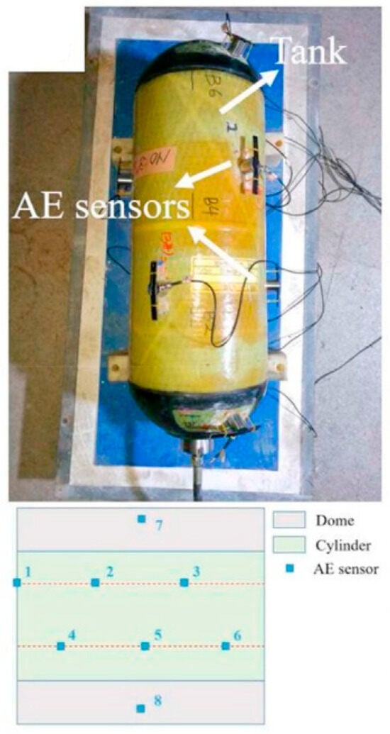
Figure 16.
Layout of acoustic emission sensors on the tank for multi-step loading tests [129].
During the composite shell manufacturing phase and resin curing, high temperature fluctuations can compromise the solidification of the resin, increasing the risk of defects such as cracks or delaminations. The use of advanced technologies for temperature-controlled curing ensures that the resin solidifies properly and maintains the necessary mechanical properties, improving the quality of the composite shell and reducing manufacturing defects [114]. Differential Scanning Calorimetry (DSC) is commonly used to analyze polymers by measuring heat flow during temperature changes. This method helps identify transitions like glass transition, melting, and crystallization, providing data on onset temperature, peak temperature, and enthalpy of these transitions [100].
Despite process optimization, minor damage may occur during the operational life of Type IV tanks. Advanced repair techniques, such as localized resin or fiber reinforcement, have been developed to extend the service life of tanks without having to completely replace them. These techniques allow the mechanical strength of the composite shell to be restored, reducing maintenance costs and increasing operational safety [37,49].
7.5. International Standards and Certifications
To ensure that Type IV tanks meet safety and quality standards, it is essential that manufacturing processes comply with international standards such as ISO 19884 and UNECE R134, which regulate the safety of high-pressure tanks for the transport and use of hydrogen [131,132]. These standards specify requirements for the design, materials, pressure testing and operational life of tanks.
Standards such as ISO 11439 and EN 12245 establish specifications for pressure tanks, defining safety requirements, compliance testing and lifecycle management protocols. These regulations cover a wide range of aspects, including pressure resistance, permeation, fire performance and structural integrity [133,134].
In addition, ISO 19881:2018 is an international standard that specifies requirements for the design, manufacture, testing, and marking of refillable containers used to store compressed hydrogen gas for land vehicle operation. These containers are permanently attached to vehicles, have a water capacity of up to 1000 L, and operate at pressures not exceeding 70 MPa. In 2025, a revised edition of ISO 19881 is under publication, set to replace the 2018 version [135].
In parallel, SAE J2579 [136] is a performance-based standard developed by SAE International that outlines safety requirements for hydrogen fuel systems in vehicles. It focuses on the design, construction, operation, and maintenance of systems that store and handle hydrogen on-board vehicles, including fuel-cell electric vehicles and hydrogen-powered internal combustion engine vehicles [136]. Table 5 reports a summary of the main protocols discussed and their main objectives. Manufacturing processes must be continuously monitored and certified to ensure compliance with these standards.
Table 5.
Main hydrogen storage system standards.
8. Reliability Analysis, Safety Considerations and Ecological Assessments
Beyond the manufacturing phase, ensuring the safe and sustainable use of Type IV tanks requires thorough evaluation.
Type IV hydrogen tanks are designed to safely store hydrogen at high pressure, but they are subject to several technical issues that can compromise their efficiency and safety over time. Understanding the failure mechanisms, along with the implementation of advanced safety measures and environmental impact assessments, is essential to ensure the long-term reliability of these tanks.
8.1. Reliability Analysis
Type IV tank failures (shown in Figure 17) can result from several factors, including hydrogen permeation, material aging and mechanical stress from repeated pressurization cycles. The main types of failure include polymer liner failures, composite shell delamination and deformation and leakage in the metal boss.
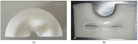
Figure 17.
Failure events: (a) half of the dome; (b) detail of cracks inside the tank [97].
- Polymer liner failures. The polymer liner, which plays a crucial role in preventing hydrogen permeation, can deteriorate due to blistering or cracking. These failures can be triggered by manufacturing defects, thermal cycling or long-term interaction with hydrogen at high pressures [97,114]. ISO 11114-4:2017 establishes requirements for material compatibility with hydrogen gas, providing guidelines to minimize these risks [137]. At high pressures and temperatures, the polymer liner can develop microcracks that compromise its sealing [36,70].
- Composite shell delamination. The composite shell is made of resin-impregnated fiber layers. Repeated stress causes delamination, or separation of the fiber layers, especially in the transition zones between the cylindrical body and the hemispherical domes. Delamination reduces the tank’s ability to withstand high pressures [100,138]. ISO/TS 15869:2009 requires that tanks used in hydrogen vehicles be tested to withstand repeated cycles without structural failure. Specifically, the standard mandates that fuel tanks be designed for 11,250 fill cycles, representing a 15-year service life for commercial heavy-duty vehicles. Alternatively, a reduced number of 5500 filling cycles may be specified for the lifetime of the vehicle, provided that a tamper-proof counter system is used to record the number of filling cycles and terminates usage of the fuel tank before the reduced number is exceeded [139]. Studies on delamination in Type IV tanks have shown that these critical issues are more evident in areas subjected to repeated stress cycles [22,140].
- Deformation and leakage in the metal boss. The metal boss, which connects the tank to the filling and exhaust systems, is a critical point of potential failure. Deformation of the boss under thermal or mechanical stress can lead to significant leakage, jeopardizing the integrity of the tank [89,141]. UNECE R134 regulates the safety of connections in hydrogen systems, with technical specifications for the mechanical resistance of metal components [132].
8.2. Security Considerations
To mitigate the risks associated with Type IV tank failures, several advanced safety measures have been implemented.
- Safety valves and relief systems. Type IV tanks are equipped with safety valves designed to gradually release the gas in the event of overpressure, thus preventing explosions or catastrophic failures [21,85]. UNECE R134 specifies safety procedures for hydrogen-powered vehicles and includes systems such as the Thermally Activated Pressure Relief Device (TPRD-less), which allows the controlled release of hydrogen in the event of a fire without the need for additional release valves [132].
- Real-time monitoring. Advanced temperature and pressure sensors are integrated into the tanks to continuously monitor operating conditions [142]. The use of AI and machine learning algorithms to detect anomalies in operating conditions is an important innovation to ensure long-term safety [28].
- Fire Protection. Another vulnerability concerns the behavior of tanks in fire conditions. When exposed to intense flames, tanks can experience degradation of the composite shell and liner, leading to structural failure and potentially hydrogen release [143,144]. Fire-resistant materials, such as ceramic fiber-reinforced composites, increase the resistance of Type IV tanks to high temperatures, providing a temporary barrier in the event of a fire [100,143]. DOT CFR 49—Part 178 establishes fire and impact resistance requirements, ensuring that tanks maintain structural integrity even during prolonged exposure to flames [145]. Shen et al., in [146], investigated the consequences associated with the explosion due to high-pressure tank rupture during fire tests. They analyzed the hazard range of the fireball for both humans and structures. The results, shown in Figure 18, indicate that humans are only safe beyond 140 m, while structures are protected at distances greater than 52 m.
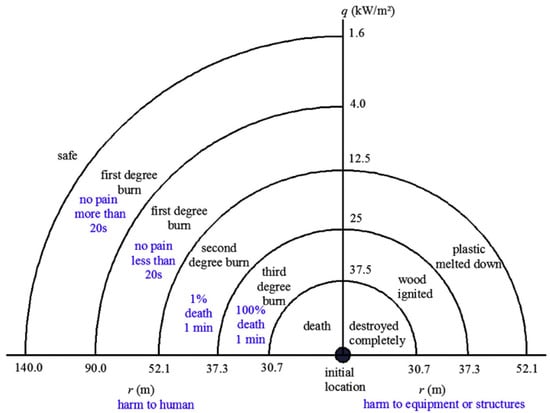 Figure 18. Hazard range of fire for equipment/structures and human [146].
8.3. Ecological Assessments
From an environmental perspective, the use of Type IV tanks promotes the adoption of hydrogen as a clean energy source, reducing greenhouse gas emissions associated with the use of fossil fuels. However, their life cycle presents some environmental issues related to production and end-of-life. A full life cycle assessment (LCA) of Type IV tanks is essential to quantify their environmental impact. This assessment considers every stage, from production to final disposal, identifying potential improvements for sustainability [34].
- Production of high-impact materials. The production of carbon fibers and polymer liners requires energy-intensive industrial processes. Currently, the energy consumption in carbon fiber manufacturing is between 100 and 900 MJ per kilogram of fiber produced, which is much higher than that of energy-intensive industries like steel production (20–30 MJ/kg). Improving energy efficiency in carbon fiber production is essential to enhance its economic viability. Potential improvements can be made at various levels of manufacturing, including the process level, virtual machine level and plant level [147].
- End-of-life and recycling. One of the main challenges related to Type IV tanks is the difficulty in recycling composite materials. Hydrogen tanks, together with fuel cells, have a marked environmental impact, more than 50% in hydrogen-based vehicles [148]. Unlike other materials, carbon fibers and polymer liners are not easily recyclable, creating disposal problems. Using recycled carbon fiber for hydrogen tanks could significantly lower environmental impacts, highlighting the need for overcoming uncertainties regarding recycled fiber use. There are three main methods for recycling carbon fiber composites, as shown in Figure 19: mechanical, thermal, and chemical. Mechanical recycling produces chopped composite materials, while thermal and chemical methods aim to recover intact fibers. Among thermal methods, pyrolysis is the most common, yielding fibers with good mechanical properties when optimized, along with by-products like fillers and hydrocarbon compounds. Chemical recycling recovers fibers by breaking down the polymer matrix through processes like solvolysis, hydrolysis, and glycolysis [149].
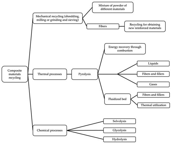 Figure 19. Composite materials recycling typologies [149].
9. Emerging Solutions and Future Developments of Type IV Tanks
The insights gained from reliability evaluations, safety considerations, and ecological assessments highlight both the strengths and the limitations of current Type IV tank technologies. Building on these findings, a detailed discussion on emerging solutions and future developments aimed at overcoming existing challenges and advancing hydrogen storage systems is required. As a matter of fact, with increasing demands for performance, efficiency and sustainability, advanced research is underway to develop emerging solutions that promise to further improve these tanks, making them safer, lighter, more durable and environmentally friendly.
9.1. Innovative Materials
One of the main goals in the development of Type IV tanks involves innovation in materials.
Regarding composite materials, in addition to traditional carbon fibers, advanced materials such as carbon nanotubes and graphene fibers are emerging as promising alternatives, with innovative structures, as depicted in Figure 20. These materials have superior tensile strength, which allows for a reduction in the overall weight of the tank without compromising mechanical strength [13,32]. Looking ahead, the adoption of hybrid fibers—combining carbon fibers with aramid or ceramic—could improve resistance to extreme conditions, such as high thermal stress and cyclic fatigue in critical areas of the tank, such as the transition zones between the dome and the cylinder [150].
Also polymer liner plays a crucial role in preventing hydrogen permeation. The introduction of nanocomposites, such as graphene, can significantly improve liner performance in terms of permeation resistance and reduce the risk of blistering and cracking [70]. Graphene, due to its two-dimensional structure, offers superior barrier properties compared to traditional polymers, thus increasing tank durability. The use of nanotechnology to strengthen polymers used in liners could extend tank lifetime by reducing deterioration caused by repeated pressurization cycles [14].
A promising innovation involves the use of shape memory materials in Type IV tanks. These materials have the ability to “remember” a predefined shape and return to it after deformation. The use of such materials could improve resistance to repeated pressure cycles, reducing the risk of permanent deformations and improving operational safety, especially in environments with variable temperatures [151].
One of the most exciting emerging innovations involves the use of self-healing polymers in the liner. These reactive materials can automatically repair microcracks or surface damage, preventing crack propagation and reducing the need for maintenance. Although this technology is still in the experimental stage, its potential to improve tank durability and safety is significant, especially in high-pressure settings [86].
Another important development is the use of advanced anti-corrosion coatings to protect both the liner and the composite shell from environmental stresses. These coatings, often based on nanocomposites or ceramic materials, can significantly improve resistance to corrosion caused by moisture, chemicals or extreme temperatures. The application of these coatings on Type IV tanks can extend the operational life and reduce the need for maintenance in harsh environmental conditions [85,152].
In the same field, an emerging area of research is the development of recycling technologies for composite materials used in Type IV tanks. Carbon fibers and polymers used in the liner are difficult to recycle, posing a challenge for long-term sustainability. However, new chemical and thermal recycling techniques are paving the way for more effective recovery of these materials, reducing the overall environmental impact. The recovery of high-quality carbon fibers from decommissioned tanks could reduce the demand for new fibers, contributing to a significant reduction in production costs and improving environmental sustainability [112,149].

Figure 20.
Hydrogen storage in different carbon-based structures: Nanoscrolls, pillared graphene, and a porous nanotube grid [153].
Looking ahead, Type V tanks, made entirely of composite materials without the use of a polymer liner, could revolutionize the hydrogen storage industry. These tanks offer the advantage of being lighter and less susceptible to permeation and liner deterioration issues [36]. At the same time, low-pressure storage technologies, such as metal hydrides or solid-phase materials, are under development and could represent the next big step forward. These technologies allow for safer hydrogen storage, reducing the risk of explosions and improving the overall sustainability of the system [145].
9.2. Intelligent Production, Monitoring and Maintenance
Advances in manufacturing processes are accelerating the production of Type IV tanks, making them more efficient and competitive. Technologies such as 3D printing for composites and automated fiber winding are improving [75,154]. Advanced automation not only reduces production times and costs but also ensures consistent quality.
In order to optimize the production processes, artificial intelligence (AI) and machine learning algorithms are increasingly used to optimize production processes. AI algorithms can be used to optimize fiber layout, improving mechanical strength and reducing tank weight. These tools consent to monitor and adjust parameters such as fiber tension and temperature in real time during resin polymerization, improving production efficiency and reducing defects. The use of AI-based predictive models helps to identify possible production problems and optimize the entire process, reducing production times by up to 25% [28,100].
According to Hu et al. [85], the integration of AI has allowed to cut down vehicle costs up to 56%. The use of predictive technologies has also improved fatigue management in composite materials, reducing the risk of structural failures.
The integration of advanced monitoring systems in Type IV tanks is one of the most promising developments. Smart sensors integrated into the tank composite allow for continuous monitoring of critical parameters such as pressure, temperature and structural health (Figure 21). These sensors can detect microcracks or delaminations before they become serious issues, thus improving safety and reducing maintenance costs [155]. In the future, the use of Internet of Things networks could enable entire tank fleets to be monitored remotely, optimizing predictive maintenance and reducing operational downtime [156].
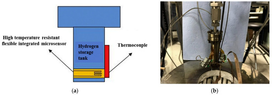
Figure 21.
Microsensor installation: (a) schematic diagram; (b) real test bench [157].
In this context, Munzke et al., in [142], demonstrated the effectiveness of integrated fiber optic sensors in distributed strain monitoring along the entire tank. These sensors can identify structural degradation up to 17,000 load cycles before complete failure, providing an additional level of safety and failure prevention. This approach improves structural monitoring compared to traditional local methods, enabling more accurate failure prediction and proactive maintenance management.
9.3. Impact of Environmental Conditions on Different Applications
Climatic and environmental conditions can significantly affect the performance of Type IV tanks. Extreme environments, such as low polar temperatures or high desert temperatures, can alter the behavior of the polymer liner and the composite shell. Thermal variations influence internal stress, increasing the risk of deformations or mechanical failures. Furthermore, prolonged exposure to high humidity or aggressive chemicals could accelerate the degradation of materials, reducing the useful life of the tank. New generations of tanks must therefore be designed taking into account these extreme conditions, with the integration of materials resistant to climatic variations [70,158].
The use of hydrogen in aircraft and ships requires storage solutions that can withstand dynamic loads and extreme environmental conditions, with the aim of reducing weight to improve vehicle efficiency. In aircraft, tanks need to be lightweight and able to withstand atmospheric pressure variations, while marine applications require tanks with increased resistance to corrosion caused by the marine environment, as reported in Figure 22 [159,160].
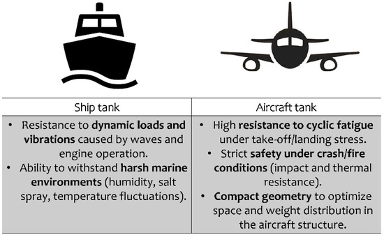
Figure 22.
Ship and aircraft tank features.
9.4. Safety and Standards
Safety in the event of fire or mechanical failure is a priority for Type IV tanks. The development of fire-retardant materials for the composite shell, combined with thermally activated pressure relief systems, reduces the risks associated with uncontrolled release of hydrogen in the event of a fire [143]. Additionally, advanced safety protocols, including early detection of microcracks and passive thermal protection, are a key barrier against catastrophic failure.
The development of Type IV tanks and emerging technologies is tightly regulated by international regulations and standards. New technologies will need to adapt to these regulations and develop new standards to support emerging innovations, ensuring that safety and reliability remain a priority. To advance this field, three key actions are recommended (Figure 23): accelerate the development of foundational standards to define hydrogen energy storage and its technical pathways; systematically develop equipment standards for hydrogen production, storage, delivery, and power generation; enhance research and standardization of critical technologies related to system integration, communication, operation, and safety to support renewable energy development [161].
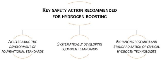
Figure 23.
Key safety action for hydrogen spreading.
9.5. Remarks and Technical Discussion
Practical deployment of hydrogen storage is ultimately decided by sector-specific figures that rarely appear in laboratory benchmarks. A recent cradle-to-grave study of 700 bar Type IV systems used in heavy-duty trucks shows that, although the tank adds only 3.5% to the tare mass, the levelized cost of stored hydrogen reaches EUR 12–14 kg−1—double the EUR 6 kg−1 calculated for 350 bar Type III bundles in stationary buffering [57]. It should be underlined that a cost decrease for the hydrogen supply chain is expected. The difference is driven less by materials than by balance-of-plant: high-pressure compressors, cascade valves and redundant TPRD-less vent lines account for 55% of the 20-year life-cycle cost in road transport, whereas the same items represent <20% in a cement-plant back-up power park where compression duty is shared among 50 tubes. Safety regulations amplify the gap; UNECE R134 obliges on-board tanks to survive a 20 m drop followed by a 30 min bonfire test, requirements that have no equivalent in stationary standards (ISO 19884). Consequently, carbon-fiber usage is 30% higher for mobility tanks, pushing embodied CO2 to 14 kg kg−1 H2—comparable to the liquefaction energy penalty of LH2 [34]. These figures explain why, despite the technical maturity of Type IV cylinders (TRL 8), fleet operators still regard hydrogen as a 1.8–2.2 × more expensive fuel pathway than battery-electric for urban buses even when green H2 is available at EUR 4 kg−1.
Looking forward, two storage options are poised for large-scale roll-out before 2030: (i) 350–700 bar Type III/IV tube-trailers for inter-terminal distribution and (ii) lined salt-cavern storage at 15–20 bar for day-to-day grid balancing. Both rely on well-characterized steels or carbon-fiber grades qualified under ISO 19881 and offer risk-mitigation roadmaps accepted by insurers. In contrast, high-gravimetric-density solutions—cryo-compressed vessels, MOF-based cryo-adsorbers and reversible borohydrides—remain at TRL 4–5. Recent independent safety screenings show that the probability of loss-of-containment for a 5 kg cryo-compressed tank (35 K, 300 bar) is 1.3 × 10⁻³ per filling, two orders of magnitude above the 10−5 target set for passenger cars [143]. Similarly, the cycle life of complex hydrides is still <300 without capacity fade, far short of the 5500 cycles required by ISO/TS 15869 for heavy-duty use. Consequently, public funding in the EU and Japan has been being redirected from materials discovery to engineering reliability of already-proven 700 bar Type IV systems, emphasizing faster filament-winding cycles (<5 min per kg H2), recyclable thermoplastic liners and AI-driven non-destructive inspection that can cut qualification time from 24 to 9 months [142]. Aligning material research with these near-term deployment bottlenecks—rather than with ultimate theoretical limits—will be critical if hydrogen storage is to move from demonstrators to revenue-generating infrastructure this decade.
10. Conclusions
This review was undertaken to distill the most recent, high-impact advances in Type IV composite hydrogen tanks—pinpointing how engineering, materials, lighter fibers, smarter geometries and embedded sensors jointly push the safety–weight–cost frontier—so that researchers and industry can immediately see which material or monitoring leap is ready for fleet adoption and which still needs laboratory proof.
Advances in Type IV hydrogen storage tanks represent a major step forward in terms of material technology and structural design, offering a promising solution for high-pressure hydrogen storage. The integration of high-density polymers for the liner and composite fiber-reinforced shells has enabled significant weight reduction, while maintaining the strength needed to handle pressures up to 70 MPa. This has played a crucial role in the expansion of the application of these tanks, especially in the mobility sector, particularly in fuel-cell vehicles. However, challenges remain regarding the durability of the materials under cyclical pressure and temperature variations. The development of cracks and delaminations due to mechanical fatigue, combined with thermal stresses caused by rapid refueling, continues to be a technical obstacle. Furthermore, the permeability of hydrogen through the liner remains a key factor affecting the long-term safety and efficiency of these tanks. Mitigating these risks through improved liner compositions, such as multilayer designs and the integration of nanomaterials, will be essential to further optimize the performance and operational lifetime of Type IV tanks.
Looking ahead, the next generation of hydrogen storage solutions will likely focus on further reducing tank weight, while improving safety through smarter designs and more accurate material selection.
In conclusion, Type IV tanks have established themselves as the standard solution for hydrogen storage, but the research to develop even lighter, safer and more efficient tanks is still ongoing. Since the adoption of hydrogen as an energy source is accelerating globally, technical developments will play a crucial role in ensuring a sustainable transition to a hydrogen economy.
Author Contributions
Conceptualization, F.P., L.P., O.C., M.G., P.F.; methodology, F.P., L.P., O.C., M.G., P.F.; software, F.P., L.P., O.C., M.G., P.F.; validation, F.P., L.P., O.C., M.G., P.F.; formal analysis, F.P., L.P., O.C., M.G., P.F.; investigation, F.P., L.P., O.C., M.G., P.F.; resources, F.P., L.P., O.C., M.G., P.F.; data curation, F.P., L.P., O.C., M.G., P.F.; writing—original draft preparation, F.P., L.P., O.C., M.G., P.F.; writing—review and editing, F.P., L.P., O.C., M.G., P.F.; visualization, F.P., L.P., O.C., M.G., P.F.; supervision, F.P., L.P., O.C., M.G., P.F. All authors have read and agreed to the published version of the manuscript.
Funding
This research received no external funding.
Data Availability Statement
No new data were created.
Acknowledgments
During the preparation of this manuscript, the authors used ChatGPT (version 4.5) for English writing revision.
Conflicts of Interest
The authors declare no conflict of interest.
References
- Dragassi, M.C.; Royon, L.; Redolfi, M.; Ammar, S. Hydrogen Storage as a Key Energy Vector for Car Transportation: A Tutorial Review. Hydrogen 2023, 4, 831–861. [Google Scholar] [CrossRef]
- Nayebossadri, S.; Walsh, M.; Smailes, M. An Overview of the Green Hydrogen Value Chain Technologies and Their Challenges for a Net-Zero Future. Hydrogen 2025, 6, 26. [Google Scholar] [CrossRef]
- James, N.; Menzies, M. Distributional Trends in the Generation and End-Use Sector of Low-Carbon Hydrogen Plants. Hydrogen 2023, 4, 174–189. [Google Scholar] [CrossRef]
- Hydrogen Council. Hydrogen for Net-Zero A Critical Cost-Competitive Energy Vector; Hydrogen Council: Brussels, Belgium, 2021. [Google Scholar]
- Pathak, P.K.; Yadav, A.K.; Padmanaban, S. Transition toward Emission-Free Energy Systems by 2050: Potential Role of Hydrogen. Int. J. Hydrogen Energy 2023, 48, 9921–9927. [Google Scholar] [CrossRef]
- Franco, A. Green Hydrogen and the Energy Transition: Hopes, Challenges, and Realistic Opportunities. Hydrogen 2025, 6, 28. [Google Scholar] [CrossRef]
- Corigliano, O.; Fragiacomo, P. Energy-Environmental Analysis of an H2PEM Power Station Assisted by a Dynamic Simulation Tool. Sustain. Energy Fuels 2025, 9, 2433–2465. [Google Scholar] [CrossRef]
- Zhou, H.; Wang, Q.; Su, Z.; Zhou, Z.; Pan, Y.; Pan, S.; Cui, D.; Bai, J.; Wu, S. Current Research, Reaction Mechanisms, and Future Prospects of Non-Precious Metal Catalysts for Ammonia Decomposition. Int. J. Hydrogen Energy 2025, 168, 150925. [Google Scholar] [CrossRef]
- Chemical Processing STUDY: Green Hydrogen Could Spur Economic and Job Growth Across Europe. Available online: https://www.chemicalprocessing.com/industrynews/news/33018751/study-green-hydrogen-could-spur-economic-and-job-growth-across-europe (accessed on 16 May 2025).
- Xie, Z.; Jin, Q.; Su, G.; Lu, W. A Review of Hydrogen Storage and Transportation: Progresses and Challenges. Energies 2024, 17, 4070. [Google Scholar] [CrossRef]
- IEA. Global Hydrogen Review 2024; IEA: Paris, France, 2024. [Google Scholar]
- Mekonnin, A.S.; Wacławiak, K.; Humayun, M.; Zhang, S.; Ullah, H. Hydrogen Storage Technology, and Its Challenges: A Review. Catalysts 2025, 15, 260. [Google Scholar] [CrossRef]
- AlZohbi, G.; Almoaikel, A.; AlShuhail, L. An Overview on the Technologies Used to Store Hydrogen. Energy Rep. 2023, 9, 28–34. [Google Scholar] [CrossRef]
- Bosu, S.; Rajamohan, N. Recent Advancements in Hydrogen Storage—Comparative Review on Methods, Operating Conditions and Challenges. Int. J. Hydrogen Energy 2024, 52, 352–370. [Google Scholar] [CrossRef]
- Nemukula, E.; Mtshali, C.B.; Nemangwele, F. Metal Hydrides for Sustainable Hydrogen Storage: A Review. Int. J. Energy Res. 2025, 2025, 6300225. [Google Scholar] [CrossRef]
- Scarpati, G.; Frasci, E.; Di Ilio, G.; Jannelli, E. A Comprehensive Review on Metal Hydrides-Based Hydrogen Storage Systems for Mobile Applications. J. Energy Storage 2024, 102, 113934. [Google Scholar] [CrossRef]
- Bellosta von Colbe, J.; Ares, J.-R.; Barale, J.; Baricco, M.; Buckley, C.; Capurso, G.; Gallandat, N.; Grant, D.M.; Guzik, M.N.; Jacob, I.; et al. Application of Hydrides in Hydrogen Storage and Compression: Achievements, Outlook and Perspectives. Int. J. Hydrogen Energy 2019, 44, 7780–7808. [Google Scholar] [CrossRef]
- Miocic, J.; Heinemann, N.; Edlmann, K.; Scafidi, J.; Molaei, F.; Alcalde, J. Underground Hydrogen Storage: A Review. Geol. Soc. Lond. Spec. Publ. 2023, 528, 73–86. [Google Scholar] [CrossRef]
- Cheng, L.; Qi, L.; Tang, X.; Li, X.; Chen, L.; Min, W.; Mei, Z.; Gao, R.; Sun, M.; Xiao, J.; et al. Effects of Hydrogen Cycling on the Performance of 70 MPa High-Pressure Hydrogen Storage Tank Liners Formed by Different Processes. Int. J. Hydrogen Energy 2024, 83, 499–511. [Google Scholar] [CrossRef]
- Ost, L.; Seidlitz, H.; Ulke-Winter, L.; Kuke, F. Development of a Spherical High-Pressure Tank for Hydrogen Storage in Mobile and Stationary Applications. Energy Technol. 2025, 13, 2300942. [Google Scholar] [CrossRef]
- Orlova, S.; Mezeckis, N.; Vasudev, V.P.K. Compression of Hydrogen Gas for Energy Storage: A Review. Latv. J. Phys. Tech. Sci. 2023, 60, 4–16. [Google Scholar] [CrossRef]
- Cheng, Q.; Zhang, R.; Shi, Z.; Lin, J. Review of Common Hydrogen Storage Tanks and Current Manufacturing Methods for Aluminium Alloy Tank Liners. Int. J. Lightweight Mater. Manuf. 2024, 7, 269–284. [Google Scholar] [CrossRef]
- Zhang, X.; Zhai, L.; Li, H.; Qi, G.; Gao, X.; Yang, W. Molecular Simulation Study on the Hydrogen Permeation Behavior and Mechanism of Common Polymers. Polymers 2024, 16, 953. [Google Scholar] [CrossRef]
- Fang, Q.; Ji, D. Molecular Simulation of Hydrogen Permeation Behavior in Liner Polymer Materials of Type IV Hydrogen Storage Vessels. Mater. Today Commun. 2023, 35, 106302. [Google Scholar] [CrossRef]
- Li, H.; Cao, X.; Liu, Y.; Shao, Y.; Nan, Z.; Teng, L.; Peng, W.; Bian, J. Safety of Hydrogen Storage and Transportation: An Overview on Mechanisms, Techniques, and Challenges. Energy Rep. 2022, 8, 6258–6269. [Google Scholar] [CrossRef]
- Magliano, A.; Perez Carrera, C.; Pappalardo, C.M.; Guida, D.; Berardi, V.P. A Comprehensive Literature Review on Hydrogen Tanks: Storage, Safety, and Structural Integrity. Appl. Sci. 2024, 14, 9348. [Google Scholar] [CrossRef]
- Jaber, M.; Yahya, A.; Arif, A.F.; Jaber, H.; Alkhedher, M. Burst Pressure Performance Comparison of Type V Hydrogen Tanks: Evaluating Various Shapes and Materials. Int. J. Hydrogen Energy 2024, 81, 906–917. [Google Scholar] [CrossRef]
- Zhang, Y.; Gu, J.; Li, Z.; Ruan, S.; Shen, C. Data-Driven Lay-up Design of a Type IV Hydrogen Storage Vessel Based on Physics-Constrained Generative Adversarial Networks (PCGANs). J. Energy Storage 2024, 98, 113130. [Google Scholar] [CrossRef]
- Ilyushechkin, A.; Schoeman, L.; Carter, L.; Hla, S.S. Material Challenges and Hydrogen Embrittlement Assessment for Hydrogen Utilisation in Industrial Scale. Hydrogen 2023, 4, 599–619. [Google Scholar] [CrossRef]
- Muthukumar, P.; Kumar, A.; Afzal, M.; Bhogilla, S.; Sharma, P.; Parida, A.; Jana, S.; Kumar, E.A.; Pai, R.K.; Jain, I.P. Review on Large-Scale Hydrogen Storage Systems for Better Sustainability. Int. J. Hydrogen Energy 2023, 48, 33223–33259. [Google Scholar] [CrossRef]
- Patel, S.K.S.; Gupta, R.K.; Rohit, M.V.; Lee, J.K. Recent Developments in Hydrogen Production, Storage, and Transportation: Challenges, Opportunities, and Perspectives. Fire 2024, 7, 233. [Google Scholar] [CrossRef]
- Abdalla, A.M.; Hossain, S.; Nisfindy, O.B.; Azad, A.T.; Dawood, M.; Azad, A.K. Hydrogen Production, Storage, Transportation and Key Challenges with Applications: A Review. Energy Convers. Manag. 2018, 165, 602–627. [Google Scholar] [CrossRef]
- Huot, J.; Lu, Z.-H.; Franco, A.; Giovannini, C. Hydrogen Gas Compression for Efficient Storage: Balancing Energy and Increasing Density. Hydrogen 2024, 5, 293–311. [Google Scholar] [CrossRef]
- Benitez, A.; Wulf, C.; de Palmenaer, A.; Lengersdorf, M.; Röding, T.; Grube, T.; Robinius, M.; Stolten, D.; Kuckshinrichs, W. Ecological Assessment of Fuel Cell Electric Vehicles with Special Focus on Type IV Carbon Fiber Hydrogen Tank. J. Clean. Prod. 2021, 278, 123277. [Google Scholar] [CrossRef]
- Rivard, E.; Trudeau, M.; Zaghib, K. Hydrogen Storage for Mobility: A Review. Materials 2019, 12, 1973. [Google Scholar] [CrossRef] [PubMed]
- Air, A.; Oromiehie, E.; Prusty, B.G. Design and Manufacture of a Type V Composite Pressure Vessel Using Automated Fibre Placement. Compos. B Eng. 2023, 266, 111027. [Google Scholar] [CrossRef]
- Air, A.; Shamsuddoha, M.; Gangadhara Prusty, B. A Review of Type V Composite Pressure Vessels and Automated Fibre Placement Based Manufacturing. Compos. B Eng. 2023, 253, 110573. [Google Scholar] [CrossRef]
- Hassan, I.A.; Ramadan, H.S.; Saleh, M.A.; Hissel, D. Hydrogen Storage Technologies for Stationary and Mobile Applications: Review, Analysis and Perspectives. Renew. Sustain. Energy Rev. 2021, 149, 111311. [Google Scholar] [CrossRef]
- Wang, H.; Gao, Y.; Wang, B.; Pan, Q.; Gan, Z. Perspective for the Safe and High-Efficiency Storage of Liquid Hydrogen: Thermal Behaviors and Insulation. Hydrogen 2024, 5, 559–573. [Google Scholar] [CrossRef]
- Zhang, T.; Uratani, J.; Huang, Y.; Xu, L.; Griffiths, S.; Ding, Y. Hydrogen Liquefaction and Storage: Recent Progress and Perspectives. Renew. Sustain. Energy Rev. 2023, 176, 113204. [Google Scholar] [CrossRef]
- Naquash, A.; Agarwal, N.; Lee, M. A Review on Liquid Hydrogen Storage: Current Status, Challenges and Future Directions. Sustainability 2024, 16, 8270. [Google Scholar] [CrossRef]
- Pistidda, C. Solid-State Hydrogen Storage for a Decarbonized Society. Hydrogen 2021, 2, 428–443. [Google Scholar] [CrossRef]
- Chanchetti, L.F.; Leiva, D.R.; Lopes de Faria, L.I.; Ishikawa, T.T. A Scientometric Review of Research in Hydrogen Storage Materials. Int. J. Hydrogen Energy 2020, 45, 5356–5366. [Google Scholar] [CrossRef]
- Siddiqui, M.J.; Balguri, P.K.; Haripriya, K.; Rajendran, A.R.; Patil, I.V. Analysis of Type IV Hydrogen Pressure Vessel with S-Glass, Carbon Fiber T700 and Kevlar Composite Materials. Mater. Today Proc. 2023, in press. [CrossRef]
- Reynolds, J.; Ali, D.; Njuguna, J.; Amadhe, F. The State of the Art in Hydrogen Storage. Green Energy Environ. Technol. 2024, 3, 1–40. [Google Scholar] [CrossRef]
- Faraj, K.; Khaled, M.; Faraj, J.; Faraj, A.; Castelain, C. Thermal Management Techniques for Enhancing Hydrogen Adsorption and Desorption in Metal Hydride Reactors: A Short Recent Review. J. Phys. Conf. Ser. 2024, 2754, 012030. [Google Scholar] [CrossRef]
- Beyazit, N.İ. Comparative Study of Hydrogen Storage and Metal Hydride Systems: Future Energy Storage Solutions. Processes 2025, 13, 1506. [Google Scholar] [CrossRef]
- Usman, M.R. Hydrogen Storage Methods: Review and Current Status. Renew. Sustain. Energy Rev. 2022, 167, 112743. [Google Scholar] [CrossRef]
- Yang, M.; Hunger, R.; Berrettoni, S.; Sprecher, B.; Wang, B. A Review of Hydrogen Storage and Transport Technologies. Clean Energy 2023, 7, 190–216. [Google Scholar] [CrossRef]
- Hua, T.Q.; Roh, H.-S.; Ahluwalia, R.K. Performance Assessment of 700-Bar Compressed Hydrogen Storage for Light Duty Fuel Cell Vehicles. Int. J. Hydrogen Energy 2017, 42, 25121–25129. [Google Scholar] [CrossRef]
- Pereira, R.; Monteiro, V.; Afonso, J.L.; Teixeira, J. Hydrogen Refueling Stations: A Review of the Technology Involved from Key Energy Consumption Processes to Related Energy Management Strategies. Energies 2024, 17, 4906. [Google Scholar] [CrossRef]
- Shin, H.K.; Ha, S.K. A Review on the Cost Analysis of Hydrogen Gas Storage Tanks for Fuel Cell Vehicles. Energies 2023, 16, 5233. [Google Scholar] [CrossRef]
- Møller, K.T.; Jensen, T.R.; Akiba, E.; Li, H. Hydrogen—A Sustainable Energy Carrier. Prog. Nat. Sci. Mater. Int. 2017, 27, 34–40. [Google Scholar] [CrossRef]
- Center for Sustainable Systems, U. of Michigan. Hydrogen Factsheet (Pub. No. CSS23-07). Available online: https://css.umich.edu/publications/factsheets/energy/hydrogen-factsheet (accessed on 17 May 2025).
- Esposito, L.; van der Wiel, M.; Acar, C. Hydrogen Storage Solutions for Residential Heating: A Thermodynamic and Economic Analysis with Scale-up Potential. Int. J. Hydrogen Energy 2024, 79, 579–593. [Google Scholar] [CrossRef]
- Burke, A.; Ogden, J.; Fulton, L. Hydrogen Storage and Transport: Technologies and Costs; Reference No. UCD-ITS-RR-24-17; Institute of Transportation Studies: Berkeley, CA, USA, 2024. [Google Scholar]
- Abdin, Z.; Khalilpour, K.; Catchpole, K. Projecting the Levelized Cost of Large Scale Hydrogen Storage for Stationary Applications. Energy Convers. Manag. 2022, 270, 116241. [Google Scholar] [CrossRef]
- Klopčič, N.; Grimmer, I.; Winkler, F.; Sartory, M.; Trattner, A. A Review on Metal Hydride Materials for Hydrogen Storage. J. Energy Storage 2023, 72, 108456. [Google Scholar] [CrossRef]
- Danebergs, J.; Deledda, S. Can Hydrogen Storage in Metal Hydrides Be Economically Competitive with Compressed and Liquid Hydrogen Storage? A Techno-Economical Perspective for the Maritime Sector. Int. J. Hydrogen Energy 2024, 50, 1040–1054. [Google Scholar] [CrossRef]
- Nyamsi, S.N.; Lototskyy, M.; Tolj, I. Selection of Metal Hydrides-Based Thermal Energy Storage: Energy Storage Efficiency and Density Targets. Int. J. Hydrogen Energy 2018, 43, 22568–22583. [Google Scholar] [CrossRef]
- Ekpotu, W.F.; Akintola, J.; Obialor, M.C.; Philemon, U.; Ekpotu, W.F.; Akintola, J.; Obialor, M.C.; Philemon, U. Historical Review of Hydrogen Energy Storage Technology. World J. Eng. Technol. 2023, 11, 454–475. [Google Scholar] [CrossRef]
- Roh, H.S.; Hua, T.Q.; Ahluwalia, R.K. Optimization of Carbon Fiber Usage in Type 4 Hydrogen Storage Tanks for Fuel Cell Automobiles. Int. J. Hydrogen Energy 2013, 38, 12795–12802. [Google Scholar] [CrossRef]
- Sgambitterra, E.; Pagnotta, L. Permeability: The Driving Force That Influences the Mechanical Behavior of Polymers Used for Hydrogen Storage and Delivery. Energies 2024, 17, 2216. [Google Scholar] [CrossRef]
- Hong, J.-H.; Han, M.-G.; Chang, S.-H. Safety Evaluation of 70MPa-Capacity Type III Hydrogen Pressure Vessel Considering Material Degradation of Composites Due to Temperature Rise. Compos. Struct. 2014, 113, 127–133. [Google Scholar] [CrossRef]
- Comond, O.; Perreux, D.; Thiebaud, F.; Weber, M. Methodology to Improve the Lifetime of Type III HP Tank with a Steel Liner. Int. J. Hydrogen Energy 2009, 34, 3077–3090. [Google Scholar] [CrossRef]
- Yuan, K.; Liu, Z. A Structural Mechanics Analysis on a Type IV Hydrogen Storage Tank during Refueling and Discharging. Eng. Fail. Anal. 2024, 165, 108822. [Google Scholar] [CrossRef]
- Kadri, K.; Ben Abdallah, A.; Ballut, S. Hydrogen Storage Vessels of Type 4 and Type 5. In Hydrogen Technologies—Advances, Insights, and Applications; IntechOpen: London, UK, 2024. [Google Scholar]
- Liu, Z.; Yuan, K.; Li, X.; Yang, D. Thermal Behavior in a Type IV Hydrogen Storage Tank of Fuel Cell Electric Vehicles under Different Charging Conditions. Int. J. Hydrogen Energy 2025, 99, 517–527. [Google Scholar] [CrossRef]
- Meyer, K.; Pignagnoli, F.; Potts, D.; Hunter, G. Lightweighting Matters in Energy Storage. Reinf. Plast. 2014, 58, 20–23. [Google Scholar] [CrossRef]
- Balasooriya, W.; Clute, C.; Schrittesser, B.; Pinter, G. A Review on Applicability, Limitations, and Improvements of Polymeric Materials in High-Pressure Hydrogen Gas Atmospheres. Polym. Rev. 2022, 62, 175–209. [Google Scholar] [CrossRef]
- Gómez, J.A.; Santos, D.M.F. The Status of On-Board Hydrogen Storage in Fuel Cell Electric Vehicles. Designs 2023, 7, 97. [Google Scholar] [CrossRef]
- Jana, S.; Parthiban, A.; Rusli, W. Polymer Material Innovations for a Green Hydrogen Economy. Chem. Commun. 2025, 61, 3233–3249. [Google Scholar] [CrossRef]
- Li, X.; Huang, Q.; Liu, Y.; Zhao, B.; Li, J. Review of the Hydrogen Permeation Test of the Polymer Liner Material of Type IV On-Board Hydrogen Storage Cylinders. Materials 2023, 16, 5366. [Google Scholar] [CrossRef] [PubMed]
- Feki, I.; Shirinbayan, M.; Nouira, S.; Bi, R.T.; Maeso, J.-B.; Thomas, C.; Fitoussi, J. Composites in High-Pressure Hydrogen Storage: A Review of Multiscale Characterization and Mechanical Behavior. Compos. Part C Open Access 2025, 16, 100555. [Google Scholar] [CrossRef]
- Sharma, P.; Neogi, S. Performance-Based Design and Manufacturing of Filament Wound Type-4 Cylinders for Compressed Gas Storage. Compos. Struct. 2023, 309, 116710. [Google Scholar] [CrossRef]
- Eko, A.J.; Epaarachchi, J.; Jewewantha, J.; Zeng, X. A Review of Type IV Composite Overwrapped Pressure Vessels. Int. J. Hydrogen Energy 2025, 109, 551–573. [Google Scholar] [CrossRef]
- Sapre, S.; Pareek, K.; Vyas, M. Investigation of Structural Stability of Type IV Compressed Hydrogen Storage Tank during Refueling of Fuel Cell Vehicle. Energy Storage 2020, 2, e150. [Google Scholar] [CrossRef]
- Zhang, Q.; Xu, H.; Jia, X.; Zu, L.; Cheng, S.; Wang, H. Design of a 70 MPa Type IV Hydrogen Storage Vessel Using Accurate Modeling Techniques for Dome Thickness Prediction. Compos. Struct. 2020, 236, 111915. [Google Scholar] [CrossRef]
- Das, S. Design and Analysis of Type IV Hydrogen Storage Pressure Vessel . Available online: https://www.researchgate.net/publication/368756849_Design_and_Analysis_of_Type_IV_Hydrogen_Storage_Pressure_Vessel?channel=doi&linkId=63f87c5457495059453dc65c&showFulltext=true (accessed on 27 May 2025).
- Wu, D.; Ren, J.; Davies, H.; Shang, J.; Haas, O. Intelligent Hydrogen Fuel Cell Range Extender for Battery Electric Vehicles. World Electr. Veh. J. 2019, 10, 29. [Google Scholar] [CrossRef]
- Alves, M.P.; Gul, W.; Cimini Junior, C.A.; Ha, S.K. A Review on Industrial Perspectives and Challenges on Material, Manufacturing, Design and Development of Compressed Hydrogen Storage Tanks for the Transportation Sector. Energies 2022, 15, 5152. [Google Scholar] [CrossRef]
- HyKit HyKit® Modular Gas Storage High-Capacity, Mobile Hydrogen. Available online: https://hykit.com/products/hykit-modular-gas-storage/#:~:text=High%2DCapacity%20635%20bar%20Storage,to%20+46%C2%B0C (accessed on 27 May 2025).
- Su, Y.; Lv, H.; Zhou, W.; Zhang, C. Review of the Hydrogen Permeability of the Liner Material of Type IV On-Board Hydrogen Storage Tank. World Electr. Veh. J. 2021, 12, 130. [Google Scholar] [CrossRef]
- Bayle, J.; Perreux, D.; Chapelle, D.; ThiÈbaud, F.; Nardin, P. A Model to Predict the Permeation of Type IV Hydrogen Tanks. In Proceedings of the 18th World Hydrogen Energy Conference 2010—WHEC 2010, Essen, Germany, 16–21 May 2010; Stolten, D., Grube, T., Eds.; 2010. Available online: https://www.osti.gov/etdeweb/servlets/purl/21400913 (accessed on 27 May 2025).
- Hu, D.; Shao, W.; Lu, D.; Xu, Y.; Wang, J. Design and Material Optimization of Carbon Fiber Composite Winding Reinforcement Layer for Vehicle Type-IV Hydrogen Storage Vessels. J. Energy Storage 2024, 100, 113459. [Google Scholar] [CrossRef]
- Jin, Z.; Su, Y.; Lv, H.; Liu, M.; Li, W.; Zhang, C. Review of Decompression Damage of the Polymer Liner of the Type IV Hydrogen Storage Tank. Polymers 2023, 15, 2258. [Google Scholar] [CrossRef] [PubMed]
- Dong, C.; Liu, Y.; Li, J.; Bin, G.; Zhou, C.; Han, W.; Li, X. Hydrogen Permeability of Polyamide 6 Used as Liner Material for Type IV On-Board Hydrogen Storage Cylinders. Polymers 2023, 15, 3715. [Google Scholar] [CrossRef]
- Villalonga, S.; Thomas, C.; Nony, C.; Thiebaud, F.; Geli, M.; Lucas, A.; Knobloch, K.; Maugy, C. Applications of Full Thermoplastic Composite for Type IV 70 MPa High Pressure Vessels. In Proceedings of the 18th International Conference on Composite Mate, Jeju Island, Republic of Korea, 21–26 August 2011. [Google Scholar] [CrossRef]
- Park, G.; Jang, H.; Kim, C. Design of Composite Layer and Liner for Structure Safety of Hydrogen Pressure Vessel (Type 4). J. Mech. Sci. Technol. 2021, 35, 3507–3517. [Google Scholar] [CrossRef]
- Li, Y.; Barzagli, F.; Liu, P.; Zhang, X.; Yang, Z.; Xiao, M.; Huang, Y.; Luo, X.; Li, C.; Luo, H.; et al. Mechanism and Evaluation of Hydrogen Permeation Barriers: A Critical Review. Ind. Eng. Chem. Res. 2023, 62, 15752–15773. [Google Scholar] [CrossRef]
- Sun, Y.; Lv, H.; Zhou, W.; Zhang, C. Research on Hydrogen Permeability of Polyamide 6 as the Liner Material for Type IV Hydrogen Storage Tank. Int. J. Hydrogen Energy 2020, 45, 24980–24990. [Google Scholar] [CrossRef]
- Lu, T.; Solis-Ramos, E.; Yi, Y.; Kumosa, M. UV Degradation Model for Polymers and Polymer Matrix Composites. Polym. Degrad. Stab. 2018, 154, 203–210. [Google Scholar] [CrossRef]
- Karapanagiotis, C.; Breithaupt, M.; Duffner, E.; Schukar, M. Real-Time Monitoring of Hydrogen Composite Pressure Vessels Using Surface-Applied Distributed Fiber Optic Sensors. J. Phys. Photonics 2025, 7, 025016. [Google Scholar] [CrossRef]
- Maus, S.; Hapke, J.; Ranong, C.N.; Wüchner, E.; Friedlmeier, G.; Wenger, D. Filling Procedure for Vehicles with Compressed Hydrogen Tanks. Int. J. Hydrogen Energy 2008, 33, 4612–4621. [Google Scholar] [CrossRef]
- Pépin, J.; Lainé, E.; Grandidier, J.C.; Benoit, G.; Mellier, D.; Weber, M.; Langlois, C. Replication of Liner Collapse Phenomenon Observed in Hyperbaric Type IV Hydrogen Storage Vessel by Explosive Decompression Experiments. Int. J. Hydrogen Energy 2018, 43, 4671–4680. [Google Scholar] [CrossRef]
- Pepin, J.; Lainé, E.; Grandidier, J.-C.; Castagnet, S.; Blanc-vannet, P.; Papin, P.; Weber, M. Determination of Key Parameters Responsible for Polymeric Liner Collapse in Hyperbaric Type IV Hydrogen Storage Vessels. Int. J. Hydrogen Energy 2018, 43, 16386–16399. [Google Scholar] [CrossRef]
- Rondinella, A.; Capurso, G.; Zanocco, M.; Basso, F.; Calligaro, C.; Menotti, D.; Agnoletti, A.; Fedrizzi, L. Study of the Failure Mechanism of a High-Density Polyethylene Liner in a Type IV High-Pressure Storage Tank. Polymers 2024, 16, 779. [Google Scholar] [CrossRef]
- Hu, Z.; Chen, M.H.; Zu, L.; Jia, X.; Shen, A.; Yang, Q.; Xu, K. Investigation on Failure Behaviors of 70 MPa Type IV Carbon Fiber Overwound Hydrogen Storage Vessels. Compos. Struct. 2021, 259, 113387. [Google Scholar] [CrossRef]
- Kis, D.I.; Kókai, E. A Review on the Factors of Liner Collapse in Type IV Hydrogen Storage Vessels. Int. J. Hydrogen Energy 2024, 50, 236–253. [Google Scholar] [CrossRef]
- Bo, K.; Feng, H.; Jiang, Y.; Deng, G.; Wang, D.; Zhang, Y. Study of Blister Phenomena on Polymer Liner of Type IV Hydrogen Storage Cylinders. Int. J. Hydrogen Energy 2024, 54, 922–936. [Google Scholar] [CrossRef]
- Dwivedi, S.K.; Vishwakarma, M. Hydrogen Embrittlement in Different Materials: A Review. Int. J. Hydrogen Energy 2018, 43, 21603–21616. [Google Scholar] [CrossRef]
- Li, J.-Q.; Li, J.-C.L.; Park, K.; Kwon, J.-T. Investigation on the Changes of Pressure and Temperature in High Pressure Filling of Hydrogen Storage Tank. Case Stud. Therm. Eng. 2022, 37, 102143. [Google Scholar] [CrossRef]
- Liu, Z.; Yuan, K.; Cheng, L.; Li, X. Thermal Management on a Type IV Storage Tank of Hydrogen Fuel Cell Electric Vehicles during Rapid Charging. Renew. Energy 2025, 245, 122825. [Google Scholar] [CrossRef]
- Melideo, D.; Baraldi, D.; Acosta-Iborra, B.; Ortiz Cebolla, R.; Moretto, P. CFD Simulations of Filling and Emptying of Hydrogen Tanks. Int. J. Hydrogen Energy 2017, 42, 7304–7313. [Google Scholar] [CrossRef]
- Castagnet, S.; Grandidier, J.-C.; Comyn, M.; Benoît, G. Hydrogen Influence on the Tensile Properties of Mono and Multi-Layer Polymers for Gas Distribution. Int. J. Hydrogen Energy 2010, 35, 7633–7640. [Google Scholar] [CrossRef]
- Castagnet, S.; Grandidier, J.-C.; Comyn, M.; Benoît, G. Mechanical Testing of Polymers in Pressurized Hydrogen: Tension, Creep and Ductile Fracture. Exp. Mech. 2012, 52, 229–239. [Google Scholar] [CrossRef]
- Merah, N.; Saghir, F.; Khan, Z.; Bazoune, A. Effect of Temperature on Tensile Properties of HDPE Pipe Material. Plast. Rubber Compos. 2006, 35, 226–230. [Google Scholar] [CrossRef]
- Melnichuk, M.; Gardavaud, Q.; Thiébaud, F.; Perreux, D. Temperature Effect in Cavitation Risk Assessments of Polymers for Hydrogen Systems. Int. J. Hydrogen Energy 2020, 45, 23020–23026. [Google Scholar] [CrossRef]
- Yersak, T.A.; Baker, D.R.; Yanagisawa, Y.; Slavik, S.; Immel, R.; Mack-Gardner, A.; Herrmann, M.; Cai, M. Predictive Model for Depressurization-Induced Blistering of Type IV Tank Liners for Hydrogen Storage. Int. J. Hydrogen Energy 2017, 42, 28910–28917. [Google Scholar] [CrossRef]
- Melnichuk, M.; Thiébaud, F.; Perreux, D. Non-Dimensional Assessments to Estimate Decompression Failure in Polymers for Hydrogen Systems. Int. J. Hydrogen Energy 2020, 45, 6738–6744. [Google Scholar] [CrossRef]
- Schäkel, M.; Janssen, H.; Brecher, C. Process Analysis of Manufacturing Thermoplastic Type-IV Composite Pressure Vessels with Helical Winding Pattern. In Proceedings of the SAMPE neXus 2021, Virtual, 29 June–1 July 2021. [Google Scholar]
- Magneville, B.; Gentilleau, B.; Villalonga, S.; Nony, F.; Galiano, H. Modeling, Parameters Identification and Experimental Validation of Composite Materials Behavior Law Used in 700 Bar Type IV Hydrogen High Pressure Storage Vessel. Int. J. Hydrogen Energy 2015, 40, 13193–13205. [Google Scholar] [CrossRef]
- Alexis, F.; Castagnet, S.; Nadot-Martin, C.; Robert, G.; Havet, P. Effect of Severe Thermo-Oxidative Aging on the Mechanical Behavior and Fatigue Durability of Short Glass Fiber Reinforced PA6/6.6. Int. J. Fatigue 2023, 166, 107280. [Google Scholar] [CrossRef]
- Zhang, M.; Lv, H.; Kang, H.; Zhou, W.; Zhang, C. A Literature Review of Failure Prediction and Analysis Methods for Composite High-Pressure Hydrogen Storage Tanks. Int. J. Hydrogen Energy 2019, 44, 25777–25799. [Google Scholar] [CrossRef]
- Liu, G.; Yang, F.; Bai, Y.; Han, C.; Liu, W.; Guo, X.; Wang, P.; Wang, R. Enhancement of Bonding Strength between Polyethylene/Graphene Flakes Composites and Stainless Steel and Its Application in Type IV Storage Tanks. J. Energy Storage 2021, 42, 103142. [Google Scholar] [CrossRef]
- Wang, X.; Tian, M.; Chen, X.; Xie, P.; Yang, J.; Chen, J.; Yang, W. Advances on Materials Design and Manufacture Technology of Plastic Liner of Type IV Hydrogen Storage Vessel. Int. J. Hydrogen Energy 2022, 47, 8382–8408. [Google Scholar] [CrossRef]
- Berro Ramirez, J.P.; Halm, D.; Grandidier, J.-C.; Villalonga, S.; Nony, F. 700 Bar Type IV High Pressure Hydrogen Storage Vessel Burst—Simulation and Experimental Validation. Int. J. Hydrogen Energy 2015, 40, 13183–13192. [Google Scholar] [CrossRef]
- Gamstedt, E.K.; Sjögren, B.A. Micromechanisms in Tension-Compression Fatigue of Composite Laminates Containing Transverse Plies. Compos. Sci. Technol. 1999, 59, 167–178. [Google Scholar] [CrossRef]
- de Miguel, N.; Acosta, B.; Baraldi, D.; Melideo, R.; Ortiz Cebolla, R.; Moretto, P. The Role of Initial Tank Temperature on Refuelling of On-Board Hydrogen Tanks. Int. J. Hydrogen Energy 2016, 41, 8606–8615. [Google Scholar] [CrossRef]
- Sapre, S.; Pareek, K.; Rohan, R.; Singh, P.K. Investigation of Compressed Hydrogen Refueling Process of 60 L Type IV Tank Used in Fuel Cell Vehicles. Energy Storage 2019, 1, e91. [Google Scholar] [CrossRef]
- Saferna, A.; Saferna, P.; Kuczyński, S.; Łaciak, M.; Szurlej, A.; Włodek, T. Thermodynamic Analysis of CNG Fast Filling Process of Composite Cylinder Type IV. Energies 2021, 14, 5568. [Google Scholar] [CrossRef]
- Lamari, F.; Weinberger, B.; Langlois, P.; Fruchart, D. Instances of Safety-Related Advances in Hydrogen as Regards Its Gaseous Transport and Buffer Storage and Its Solid-State Storage. Hydrogen 2024, 5, 387–402. [Google Scholar] [CrossRef]
- Zhu, J.; Li, Y.; Cao, W.; Li, Y.; Gao, Z. Failure Analysis of Novel BOSS Structures for Type IV Hydrogen Storage Vessels. Energies 2023, 16, 4005. [Google Scholar] [CrossRef]
- Moradi, R.; Groth, K.M. Hydrogen Storage and Delivery: Review of the State of the Art Technologies and Risk and Reliability Analysis. Int. J. Hydrogen Energy 2019, 44, 12254–12269. [Google Scholar] [CrossRef]
- Gupta, C.; Kumar, S.; Poonia, S.; Pareek, K. Refueling Analysis of Type IV Composite Tank as per SAEJ2601 with Refueling Station Configuration. Int. J. Hydrogen Energy 2024, 78, 970–983. [Google Scholar] [CrossRef]
- Li, J.; Liu, J.; Zhao, B.; Wang, D.; Guo, S.; Song, J.; Li, X. Research on Temperature Rise of Type IV Composite Hydrogen Storage Cylinders in Hydrogen Fast-Filling Process. Energies 2023, 16, 2918. [Google Scholar] [CrossRef]
- Huang, Q.; Li, X.; Li, J.; Liu, Y.; Li, X.; Zhu, C. Overview of Standards on Pressure Cycling Test for On-Board Composite Hydrogen Storage Cylinders. In Proceedings of the ASME 2022 Pressure Vessels & Piping Conference, Las Vegas, NV, USA, 17–22 July 2022; American Society of Mechanical Engineers, Pressure Vessels and Piping Division (Publication) PVP: West Conshohocken, PA, USA, 2022; Volume 1. [Google Scholar] [CrossRef]
- Błachut, A.; Wollmann, T.; Panek, M.; Vater, M.; Kaleta, J.; Detyna, J.; Hoschützky, S.; Gude, M. Influence of Fiber Tension during Filament Winding on the Mechanical Properties of Composite Pressure Vessels. Compos. Struct. 2023, 304, 116337. [Google Scholar] [CrossRef]
- Wang, D.; Liao, B.; Hao, C.; Wen, A.; Zheng, J.; Jiang, P.; Gu, C.; Xu, P.; Huang, Q. Acoustic Emission Characteristics of Used 70 MPa Type IV Hydrogen Storage Tanks during Hydrostatic Burst Tests. Int. J. Hydrogen Energy 2021, 46, 12605–12614. [Google Scholar] [CrossRef]
- Pritchard, A.; McCourt, M.; Martin, P.; Kearns, M. The Encapsulation of Metal Boss Components within Rotomoulded Liners for Type IV H2 Tanks. AIP Conf. Proc. 2023, 2884, 230001. [Google Scholar] [CrossRef]
- ISO/DIS 19884 (En); Gaseous Hydrogen—Cylinders and Tubes for Stationary Storage. International Organization for Standardization: Geneva, Switzerland, 2018. Available online: https://www.iso.org/obp/ui/#iso:std:iso:19884:dis:ed-1:v1:en (accessed on 9 June 2025).
- Ufficio delle Pubblicazioni dell’Unione Europea. Regolamento n. 134 della Commissione Economica per l’Europa delle Nazioni Unite (UNECE)—Disposizioni Uniformi Concernenti L’omologazione dei Veicoli a Motore e dei Relativi Componenti per Quanto Riguarda le Prestazioni in Termini di Sicurezza dei Veicoli Alimentati a Idrogeno (HFCV) [2019/795], 2019. Available online: https://op.europa.eu/it/publication-detail/-/publication/8aad3d19-7870-11e9-9f05-01aa75ed71a1/language-it (accessed on 27 May 2025).
- ISO 11439:2013; Gas Cylinders—High Pressure Cylinders for the on-Board Storage of Natural Gas as a Fuel for Automotive Vehicles. International Organization for Standardization: Geneva, Switzerland, 2013. Available online: https://www.iso.org/standard/44755.html (accessed on 9 June 2025).
- UNI EN 12245:2022; UNI Ente Italiano Di Normazione. UNI: Milan, Italy, 2022. Available online: https://store.uni.com/uni-en-12245-2022 (accessed on 9 June 2025).
- ISO 19881:2018; Gaseous Hydrogen—Land Vehicle Fuel Containers. International Organization for Standardization: Geneva, Switzerland, 2018. Available online: https://www.iso.org/standard/65029.html (accessed on 9 June 2025).
- J2579_202301; Standard for Fuel Systems in Fuel Cell and Other Hydrogen Vehicles. SAE International: Warrendale, PA, USA, 2023. [CrossRef]
- ISO 11114-4:2017; Transportable Gas Cylinders—Compatibility of Cylinder and Valve Materials with Gas Contents—Part 4: Test Methods for Selecting Steels Resistant to Hydrogen Embrittlement. International Organization for Standardization: Geneva, Switzerland, 2017. Available online: https://www.iso.org/standard/64587.html (accessed on 9 June 2025).
- Hokine, A.; Ghouaoula, A.; Achira, F.K.; Medjdoub, S.M. Analysis of Failure Pressures of Composite Cylinders with a Polymer Liner of Type IV CNG Vessels. Int. J. Mech. Aerosp. Ind. Mechatron. Eng. 2013, 7, 148–152. [Google Scholar]
- ISO/TS 15869:2009; Gaseous Hydrogen and Hydrogen Blends—Land Vehicle Fuel Tanks. International Organization for Standardization: Geneva, Switzerland, 2009. Available online: https://www.iso.org/standard/52871.html (accessed on 10 June 2025).
- Bouhala, L.; Koutsawa, Y.; Karatrantos, A.; Bayreuther, C. Design of Type-IV Composite Pressure Vessel Based on Comparative Analysis of Numerical Methods for Modeling Type-III Vessels. J. Compos. Sci. 2024, 8, 40. [Google Scholar] [CrossRef]
- Leh, D.; Saffré, P.; Francescato, P.; Arrieux, R.; Villalonga, S. A Progressive Failure Analysis of a 700-Bar Type IV Hydrogen Composite Pressure Vessel. Int. J. Hydrogen Energy 2015, 40, 13206–13214. [Google Scholar] [CrossRef]
- Munzke, D.; Duffner, E.; Eisermann, R.; Schukar, M.; Schoppa, A.; Szczepaniak, M.; Strohhäcker, J.; Mair, G. Monitoring of Type IV Composite Pressure Vessels with Multilayer Fully Integrated Optical Fiber Based Distributed Strain Sensing. Mater. Today Proc. 2021, 34, 217–223. [Google Scholar] [CrossRef]
- Molkov, V.; Kashkarov, S.; Makarov, D.; Fletcher, J.; Rattigan, W. Explosion Free in Fire Self-Venting (TPRD-Less) Type IV Tanks: Validation under Extreme Impinging 70 MPa Hydrogen Jet Fire Conditions. Int. J. Hydrogen Energy 2023, 48, 40117–40126. [Google Scholar] [CrossRef]
- Kashkarov, S.; Makarov, D.; Molkov, V. Performance of Hydrogen Storage Tanks of Type IV in a Fire: Effect of the State of Charge. Hydrogen 2021, 2, 386–398. [Google Scholar] [CrossRef]
- ECFR: 49 CFR Part 178—Specifications for Packagings. Available online: https://www.ecfr.gov/current/title-49/subtitle-B/chapter-I/subchapter-C/part-178 (accessed on 12 June 2025).
- Shen, C.; Ma, L.; Huang, G.; Wu, Y.; Zheng, J.; Liu, Y.; Hu, J. Consequence Assessment of High-Pressure Hydrogen Storage Tank Rupture during Fire Test. J. Loss Prev. Process Ind. 2018, 55, 223–231. [Google Scholar] [CrossRef]
- Khayyam, H.; Naebe, M.; Milani, A.S.; Fakhrhoseini, S.M.; Date, A.; Shabani, B.; Atkiss, S.; Ramakrishna, S.; Fox, B.; Jazar, R.N. Improving Energy Efficiency of Carbon Fiber Manufacturing through Waste Heat Recovery: A Circular Economy Approach with Machine Learning. Energy 2021, 225, 120113. [Google Scholar] [CrossRef]
- Miotti, M.; Hofer, J.; Bauer, C. Integrated Environmental and Economic Assessment of Current and Future Fuel Cell Vehicles. Int. J. Life Cycle Assess. 2017, 22, 94–110. [Google Scholar] [CrossRef]
- Butenegro, J.A.; Bahrami, M.; Abenojar, J.; Martínez, M.Á. Recent Progress in Carbon Fiber Reinforced Polymers Recycling: A Review of Recycling Methods and Reuse of Carbon Fibers. Materials 2021, 14, 6401. [Google Scholar] [CrossRef] [PubMed]
- Johnson, K.; Veenstra, M.J.; Gotthold, D.; Simmons, K.; Alvine, K.; Hobein, B.; Houston, D.; Newhouse, N.; Yeggy, B.; Vaipan, A.; et al. Advancements and Opportunities for On-Board 700 Bar Compressed Hydrogen Tanks in the Progression Towards the Commercialization of Fuel Cell Vehicles. SAE Int. J. Altern. Powertrains 2017, 6, 201–218. [Google Scholar] [CrossRef]
- Amadi, A.; Mohyaldinn, M.; Moses, P.R.; Benaarbia, A. Hydrogen-Resistant Materials: A Review Exploring Shape Memory Alloys, Medium and High Entropy Alloys to Project the Potentials of a High Entropy Shape Memory Alloy. J. Alloys Compd. Commun. 2025, 6, 100054. [Google Scholar] [CrossRef]
- Yuan, S.; Sun, Y.; Yang, C.; Zhang, Y.; Cong, C.; Yuan, Y.; Lin, D.; Pei, L.; Zhu, Y.; Wang, H. A Novel Dual-Functional Epoxy-Based Composite Coating with Exceptional Anti-Corrosion and Enhanced Hydrogen Gas Barrier Properties. Chem. Eng. J. 2022, 449, 137876. [Google Scholar] [CrossRef]
- Froudakis, G.E. Hydrogen Storage in Nanotubes & Nanostructures. Mater. Today 2011, 14, 324–328. [Google Scholar] [CrossRef]
- Kreider, M.C.; Sefa, M.; Fedchak, J.A.; Scherschligt, J.; Bible, M.; Natarajan, B.; Klimov, N.N.; Miller, A.E.; Ahmed, Z.; Hartings, M.R. Toward 3D Printed Hydrogen Storage Materials Made with ABS-MOF Composites. Polym. Adv. Technol. 2018, 29, 867–873. [Google Scholar] [CrossRef] [PubMed]
- Lee, C.Y.; Shen, C.C.; Chiu, C.W.; Hsieh, H. Te Real-Time Micro-Monitoring of Surface Temperature and Strain of Magnesium Hydrogen Tank through Self-Made Two-In-One Flexible High-Temperature Micro-Sensor. Micromachines 2022, 13, 1370. [Google Scholar] [CrossRef] [PubMed]
- Priya, M.P.A.; Karthikeyani, P.; Arunfred, N.; Hariharan, M.; Ramyadevi, K.; Murugan, S. IoT and Hydrogen Transport: Revolutionizing Fuel Cell Vehicle Infrastructure. In Proceedings of the 4th International Conference on Innovative Practices in Technology and Management 2024, ICIPTM 2024, Noida, India, 21–23 February 2024. [Google Scholar] [CrossRef]
- Lee, C.Y.; Shen, C.C.; Lee, S.J.; Chiu, C.W.; Lin, H.T. Real-Time Microscopic Monitoring of Temperature and Strain on the Surface of Magnesium Hydrogen Storage Tank by High Temperature Resistant Flexible Integrated Microsensor. Int. J. Hydrogen Energy 2022, 47, 12815–12821. [Google Scholar] [CrossRef]
- Nakashima, K.; Morillo, C.; Kurono, Y.; Sawae, Y.; Sugimura, J. Wear Mechanisms of Ptfe in Humidified Hydrogen Gas. In American Society of Mechanical Engineers, Tribology Division, TRIB, Proceedings of the ASME/STLE 2011 International Joint Tribology Conference, Los Angeles, CA, USA, 24–26 October 2011; ASME: New York, NY, USA, 2011; pp. 229–231. [Google Scholar] [CrossRef]
- The Future of Hydrogen—Analysis—IEA. Available online: https://www.iea.org/reports/the-future-of-hydrogen (accessed on 9 April 2025).
- Li, J.-C.; Xu, H.; Zhou, K.; Li, J.-Q. A Review on the Research Progress and Application of Compressed Hydrogen in the Marine Hydrogen Fuel Cell Power System. Heliyon 2024, 10, e25304. [Google Scholar] [CrossRef] [PubMed]
- Ye, X.; Yang, Y.; Feng, Y.; Zhou, L. Development and Deployment of Standards for Hydrogen Energy Storage Systems. In Proceedings of the 2024 4th International Conference on Smart Grid and Energy Internet, SGEI 2024, Shenyang, China, 13–15 December 2024; pp. 89–94. [Google Scholar] [CrossRef]
Disclaimer/Publisher’s Note: The statements, opinions and data contained in all publications are solely those of the individual author(s) and contributor(s) and not of MDPI and/or the editor(s). MDPI and/or the editor(s) disclaim responsibility for any injury to people or property resulting from any ideas, methods, instructions or products referred to in the content. |
© 2025 by the authors. Licensee MDPI, Basel, Switzerland. This article is an open access article distributed under the terms and conditions of the Creative Commons Attribution (CC BY) license (https://creativecommons.org/licenses/by/4.0/).