1. Introduction
According to a 2020 study conducted by the International Maritime Organization (IMO), greenhouse gas (GHG) emissions from shipping have increased from 977 million tonnes in 2012 to 1.1 billion tonnes in 2018, representing a 9.6% rise [
1]. In an effort to reach carbon neutrality, the IMO introduced the revised GHG Strategy during its Marine Environment Protection Committee (MEPC) 80 meeting, setting an enhanced common ambition to reach net-zero GHG emissions from international shipping by or around 2050 [
2]. The strategy also includes a commitment to ensure the uptake of alternative zero and near-zero GHG emission fuels by 2030. Additionally, 195 parties have joined the Paris Agreement [
3]. As part of the agreement, Australia has committed to reduce GHG emissions by 43% by 2030 and reach net-zero emissions by 2050. The Low Emissions Technology Statements (LETS) highlight Australia’s ambition to become a world-leading clean hydrogen producer and exporter, identifying clean hydrogen as one of the priority low emissions technologies [
4].
In recent years, Australia’s domestic maritime GHG emissions have persisted at around 2 million tonnes annually, accounting for approximately 0.4% of the nation’s total annual emissions [
5]. The Australian maritime fleet is predominantly composed of small domestic commercial vessels (DCVs), which are the largest contributors of GHG emissions from Australian vessels. Over 8700 vessels operating in Australian waters with valid certificates of survey are less than 50 m in length and more than 80% of these vessels have the potential to be replaced with zero-emission power systems in the next 10–20 years [
5]. Zero-emission technologies for maritime vessels each have distinct strengths and weaknesses. Battery electric propulsion offers high efficiency but is limited by energy density and charging infrastructure [
6,
7]. Hydrogen power systems provide fast refuelling but face challenges in logistic, storage, and conversion efficiency [
8,
9,
10]. Green ammonia and methanol power systems can leverage existing bunkering infrastructure but require advancements in supply chains and engine technology [
7,
11,
12]. The maritime industry’s transition to zero-emission solutions will require a balanced approach that considers energy density, operational flexibility, and infrastructure readiness.
A study [
13] concluded that fuel cell (FC) technology has the potential of being more efficient and cleaner than conventional internal combustion engines (ICEs) and gas turbines. However, nearly a decade later, the design and development of hydrogen-fuelled vessels (HFVs) remain complex, requiring solutions to numerous design challenges [
8,
9,
10,
14]. The most prominent challenges arise from the properties of hydrogen: it is a highly flammable gas prone to leaks and is deeply cryogenic in its liquid state. Combined with its relatively low volumetric energy density, these characteristics introduce complications regarding fuel storage, including storage methods, materials, space requirements, and locational constraints. Nonetheless, hydrogen is suitable for marine applications, as its risks and hazards are well understood [
15]. The maritime use of FCs and compressed hydrogen (CH
2) high-pressure cylinders are now commercially available [
5], and the cost of green hydrogen in Australia is projected to decrease to levels comparable to fossil fuels, with the Australian government setting a stretch goal of under AUD 2 per kg of H
2 [
16].
This paper investigates the feasibility of retrofitting a conventionally fuelled vessel with hydrogen power systems. The research explores various design challenges with reference to classification society requirements and analyses the feasibility of such undertakings through an asset management (AM) approach.
2. Scope and Methodology
The retrofit design of a hydrogen-fuelled vessel (HFV) is dictated by various technical and commercial considerations, primarily established by regulatory bodies, and the assessment of cost, risk, and performance. Ideally, a retrofitted HFV should maintain the safety, capabilities, functionality, and economic viability of the benchmark conventional vessel. This includes, but is not limited to, considerations of the vessel’s mission statement, tank capacities, bunkering requirements, safety ratings, and hydrostatics. However, achieving these objectives is challenging in retrofit applications due to the unique design constraints associated with hydrogen power systems.
This paper examines these challenges through a detailed case study of a conventionally powered (marine diesel oil, MDO-fuelled), non-self-propelled aquaculture feed barge. The study provides theoretical yet pragmatic insights into the feasibility of retrofit applications within the Australian context. The retrofit specifications are evaluated in alignment with AM principles, design and system considerations, and the guidelines set forth by the relevant classification societies, international codes, and Australian regulations.
AM principles are the key methodology employed in conducting the feasibility studies. As stated in the literature [
17], “Balancing cost, risk, and performance is the essence of value generation in any asset management system and forms an integral part of the decision-making process. Regardless of the approach, every decision in asset management should consider the elements of cost-effectiveness and risk moderation. Moreover, balancing cost, risk, and performance also depends upon the distinctiveness of the value. Applying one specific methodology to all scenarios is not practical”. The author of the publication [
17] also postulates that “any AM activity, problem, issue, and/or solution from tactical to strategic level has cost, risk, and performance elements inherently embedded in it in a certain percentage composition; this is called Asset management Value (AMV) balance”. The empirical equations provided below define this balance [
17].
The value can be tangible or intangible, financial or non-financial, and is measured either quantitatively or qualitatively with regard to the application and its intended objective. The international standard on risk management, ISO 31000 [
18], indicates that risk has a negative effect on objectives. Cost is also considered a negative effect; thus, as depicted in Equation (1), value can be expressed as performance minus cost, considering the associated risks. In this study, the vessel’s performance is defined by its efficiency and ability to fulfil its mission. This refers to its fish feed capacity and the duration it can operate before returning to port or conducting bunkering operations. The cost and risk aspects refer to the commercial and technical considerations. Overall, the AM approach helps to identify the determining factors of the feasibility criteria and highlights the aspects that must be addressed to move toward a feasible application.
3. Overview of Hydrogen-Fuelled Vessels
Fundamentally, an HFV uses hydrogen fuel to generate electricity via FCs, powering onboard systems and storing energy in batteries for hybrid power generation and auxiliary power. These onboard systems have increased risks, higher overall costs, and relatively compromised performance compared to a conventional vessel. This is due to the major design challenges of a hydrogen power system, particularly considering the current state of technology and infrastructure in the maritime industry. The following subsections provide overviews of the three main systems that dictate and define the design of an HFV.
3.1. Fuel Hydrogen
The onboard storage of hydrogen presents a significant challenge that must be addressed in retrofit applications. Hydrogen’s low volumetric energy density compared to conventional diesel oil necessitates the use of larger tanks to achieve equivalent energy storage capacity. Regardless of vessel size, ensuring sufficient hydrogen storage space remains a fundamental challenge in ship design [
19,
20,
21]. Additionally, its extremely low flashpoint imposes stringent requirements on the storage method, location, and area to ensure safety. Hydrogen’s low fluid density can lead to unfavourable changes in weight distribution, which may adversely impact the stability of a conventional MDO vessel in retrofitting applications. Furthermore, hydrogen’s small molecular size makes it susceptible to causing hydrogen embrittlement in storage tanks—a process where hydrogen atoms diffuse into metals, reducing ductility and compromising the structural integrity of the tanks [
22]. To mitigate this phenomenon, industry-proven solutions include specially engineered alloys, protective coatings, and corrosion inhibitors. However, these measures increase both procurement and storage costs. In maritime applications, hydrogen is predominantly stored as CH
2 or liquid hydrogen (LH
2), each with its own set of technical and economic considerations.
LH
2 offers a relatively higher energy density but requires cryogenic storage at approximately −253 °C, necessitating insulated tanks and incurring significant storage and production demands [
23,
24]. Producing LH
2 also requires considerable energy to cool hydrogen below its critical point, contributing to higher production costs. CH
2, on the other hand, is stored in high-pressure tanks, typically ranging from 250 to 700 bar, which demands more storage space for an equivalent energy supply [
23]. According to the literature [
25], CH
2 is the most common storage method for hydrogen in mobility applications due to its technological maturity, wide availability, and cost-effectiveness. However, CH
2’s lower volumetric energy density necessitates more frequent bunkering compared to LH
2.
While LH
2 offers superior energy density and reduced storage volume requirements, its production, procurement, and storage are more expensive [
26]. In contrast, CH
2 benefits from more established infrastructure and widespread adoption in both maritime and automotive industries, reducing overall costs and risks related to production, bunkering, and storage. Within the Australian context, the infrastructure for CH
2 production and bunkering is more developed than for LH
2 [
27], making it a more suitable choice for domestic vessels. As such, CH
2 is selected for consideration in this study.
3.2. Prime Mover—Hydrogen Fuel Cells
Hydrogen power systems typically operate using FCs or ICEs. FCs convert hydrogen into electricity, while ICEs use hydrogen as a fuel to generate thermal energy. Hydrogen FCs are more efficient than ICEs in terms of the power output and GHG emissions. However, for small vessels, FCs and their associated systems can often occupy relatively more space for equivalent energy output and therefore prompt greater spatial requirements, which may compromise useful space on board. Hydrogen ICE technologies are currently not as developed and refined as FCs for maritime applications. Thus, at present, FCs are more favourable in the development of zero-emission hydrogen-powered vessels, especially as FC technology becomes more advanced and readily available, ultimately reducing cost and becoming more accessible. They are especially feasible in vessels that are unmanned and not self-propelled, which require less maintenance-intensive systems on board and a relatively less comprehensive approach to the design in terms of the onboard systems and crew safety considerations. This study considers Proton Exchange Membrane (PEM) FCs for the investigation in order to align with the goal of achieving net-zero emissions by 2050.
3.3. Energy Storage—Batteries
During routine operations, a vessel may be subject to several load variations, which cannot always be satisfied via FCs due to their longer response times. To satisfy the power demand in these conditions, HFVs are often fitted with an electrical energy storage system (ESS) such as batteries. These batteries provide a form of hybrid power system that addresses adverse energy gradients, powers auxiliary systems, and provides powering redundancy in the case of a single failure [
8]. Excess electricity generated by FCs during lower power demands is stored in the batteries [
28]. Lithium-ion (Li-ion) and lithium-polymer (LiPo) are the two most commonly used battery types in marine applications, which use a liquid and solid electrolyte, respectively. Li-ion batteries often have a relatively higher energy density; however, LiPo batteries are lighter, flexible, leak-resistant, and capable of being engineered into any shape, making them safer and more suitable for maritime applications [
29]. Nonetheless, Li-ion batteries are more refined and readily available due to their widespread use across many industries, and thus incur reduced costs in comparison to LiPo batteries.
4. Design Considerations
The design of an HFV contains several systems which may not be found on conventional MDO vessels. The high-risk environment of an HFV prompts specific consideration to the onboard systems and special requirements for compliance with classification society rules and international codes [
30]. Specific prescriptive IMO regulations are not yet in place for the use of hydrogen as a marine fuel; however, the International Convention for the Safety of Life at Sea (SOLAS) II-I opens the way for a structured design process based on risk assessments in cases where a ship is deviating from prescribed rules [
31]. In terms of utilising FC, the IMO has issued the Interim Guidelines for the Safety of Ships Using FC Power Installations (MSC.1/Circ.1647) [
32]. The main international code applicable to vessels using alternative fuels is the International Code of Safety for Ships Using Gases or Other Low-flashpoint Fuels (IGF Code) [
33]. Currently, the IGF Code only provides requirments for liquified natural gas-fuelled vessels and refers to the alternative design approach for the approval of using hydrogen and other fuels. The approach requires a risk-based approval process to obtain an equivalent level of safety compared to a conventionally fuelled ship [
34]. The IGF Code working group plans to completed drafting interim guidelines for hydrogen-fuelled ships until 2026 [
35]. Many classification societies provide rules or guidelines for HFVs, such as ABS [
36], BV [
37], CCS [
38], DNV [
39], KR [
40], LR [
41], and RINA [
42]. Some of them are appointed as Australian Maritime Safety Authority (AMSA)-recognised organisations [
43]. This section provides an overview of the systematic considerations, which directly impact the vessel’s general arrangement design, with reference to class rules provided by BV [
37].
4.1. Safety Assessment
Risk assessments, such as Hazard Identification (HAZID), Failure Modes, Effects, and Criticality Analysis (FMECA), and Hazard and Operability Studies (HAZOP), are required to ensure that any risks arising from the use of hydrogen affecting persons on board, the environment, the structural strength, and the integrity of the ship are addressed. These documents are highly technical and require extensive analysis of system interactions to assess the potential risks and propose mitigation measures. Nonetheless, the classification society rules set the basis for a safe design.
The high-risk environment of an HFV presents various areas of concern in terms of safety, leading to several limitations on the use of available space and accessible areas [
44,
45]. Therefore, the vessel design is majorly affected by the safety considerations. Nonetheless, these considerations can be eased on unmanned vessels, such as the barge considered in this paper, as they provide more opportunity to optimise the useful space onboard by having relatively higher allowable risks and hazardous areas in the absence of crew. Hydrogen bunkering is also considered a high-risk operation where classification societies define various rules. These considerations include, but are not limited to, the load on bunkering manifolds, hose material grades, locational constraints, piping routes and connections, monitoring and alarms, ventilation, redundancy, and emergency measures [
8].
4.2. Arrangement on Board
The arrangement and location of spaces for hydrogen storage, distribution, and use should be designed to minimise the number and extent of hazardous areas. These spaces should be arranged to prevent the accumulation of hydrogen by having simple geometric shapes, sloping ceilings, and avoiding obstructing structure in the upper part. Additionally, several design restrictions should be applied to hazardous areas onboard, limiting accesses, outlets, inlets, and the overall general arrangement.
4.2.1. Hydrogen Fuel Location and Arrangement
Hydrogen fuel tanks should be located such that they are protected from external damage caused by a collision or grounding. The rules and regulations can vary across different classification societies; however, it is a common commandment to not locate hydrogen tanks within machinery spaces, cargo spaces, service spaces, or accommodation spaces. Generally, tanks are not to be installed in congested areas. This also includes tanks or equipment located on an open deck where sufficient natural ventilation should be warranted to prevent the accumulation of escaped hydrogen.
4.2.2. Compressed and Portable Hydrogen Tanks
CH2 tanks are generally not allowed to be stored in enclosed spaces. However, this is subject to special consideration in accordance with the classification society requirements and risk assessments. As a minimum, CH2 tanks in enclosed spaces must have adequate means to depressurise and avoid a hazardous atmosphere. Suitable protection must be provided on all surfaces within the enclosed space to protect against any lost high-pressure hydrogen gas unless the bulkheads are designed for the lowest temperature that can arise from hydrogen expansion leakage. A fire extinguishing system must be installed along with a mechanical forced ventilation system that is sufficient in diluting to an average gas concentration below 25% of the lower explosive limit (LEL) in all maximum probable leakage scenarios. Spaces used for the storage of CH2 are not to be used for the storage of other combustibles, tools, or objects not part of the hydrogen distribution system. Sources of heat must be kept clear in these spaces. On open decks, cylinders are to be properly secured, and all valves, pressure regulators, and pipes leading from such cylinders are to be protected against mechanical damage. Portable hydrogen fuel tanks are to be located in dedicated spaces where if located in an enclosed space, that area is considered to be a tank connection space. Containerised fuel tanks on open deck may be considered as an enclosed or semi-enclosed space if the ventilation around the tank is not sufficient.
4.2.3. Tank Connection, Fuel Preparation, Machinery, and Gas Valve Unit Spaces
All tank connections, fittings, flanges, and tank valves are normally enclosed in a gastight tank connection space unless located on an open deck. The space is to safely contain leakage from the tank and ensure that the hull structure will not be exposed to unacceptable cooling in the case of leakage from the tank connections. The space must be designed to withstand the maximum pressure buildup during a leakage scenario or alternatively, pressure relief venting must to provided to a safe location. Access to the tank connection space is to be arranged as a bolted hatch or a gastight door and an airlock unless the space is independent and direct from the open deck. Fuel preparation rooms are required to accommodate the systems associated with LH2 storage, whereas for CH2 applications, all associated systems can be incorporated into the tank connection space. The machinery space is to be arranged to ensure that it is gas safe under all conditions. This infers that a single failure is to not lead to the release of hydrogen into the machinery space. Risk assessments are required to ensure acceptable safety ratings if the machinery space contains any engines, hydrogen-fuelled or not. Gas valve unit (GVU) spaces may be located in tank connection spaces, fuel preparation rooms, an enclosed space within the machinery room, or an independent space that fulfils the criteria of a fuel preparation room with respect to location, access, ventilation, and gas detection. Access to GVU rooms must be arranged through an airlock from gas-safe hydrogen consumer machinery spaces. To reduce the response time in case of load variation and to limit the amount of hydrogen released in the case of a leakage, GVUs are usually located within close proximity to hydrogen consumers.
4.2.4. Fuel Bunkering Station
The bunkering station should generally be located on open deck with sufficient natural ventilation. For closed or semi-closed bunkering stations, gas- and liquid-tight boundaries against enclosed spaces are normally required and are subject to special considerations based on risk assessment. The space must be arranged for the safe management of fuel spills and to prevent hull or deck structures from being exposed to excessive low temperatures in the event of any leakage.
4.3. Control of Atmosphere
The ventilation requirements of a space are usually determined by measures and estimations based on hydrogen leakage rate under normal operation. Ventilation capacity requirements are generally a function of the total volume of the room; however, an increased capacity may be necessary for rooms with complicated geometries. Some spaces may also utilise inert gas, such as nitrogen, to control the risky and hazardous nature of a given atmosphere. Nonetheless, gas or vapour detection devices are required to be fitted in any space containing hydrogen-related equipment, components, or piping. The number of detectors and their location are determined in accordance with the size, layout, and ventilation of the space.
Entry openings from non-hazardous to hazardous spaces must be arranged with airlocks. The ducting arrangement of hazardous spaces must be designed to eliminate the possibility of hydrogen accumulation, thus running continuously upward from the ventilated space up to the ventilation outlet without small radii of curvatures. The ducting for hazardous spaces is required to be separated from the ducting of non-hazardous spaces. Outlets from hazardous enclosed spaces must be located in an open area that, in the absence of the considered outlet, would be of the same or lesser hazard than the ventilated space.
Mechanical ventilation systems are required in spaces where hydrogen accumulation must be avoided. This generally consists of independent fans of a sufficient combined capacity to dilute the hydrogen concentration to an acceptable level even in the case of circuit failure. The fans are required to be of a non-sparking type that are approved by the society. As a general rule, the ventilation systems in tank connections spaces, fuel preparation rooms, machinery spaces, and gas valve unit spaces must be able to withstand the respective maximum pressure in case of hydrogen leakage. The space must provide a ventilation capacity sufficient to dilute the average gas or vapour concentration to below 25% of the LEL in all maximum probable leakage scenarios.
5. Feasibility of Achieving Equivalent Performance
Retrofitting conventional vessels with hydrogen fuel often results in reduced performance, higher costs, and increased risks compared to their conventional counterparts. To assess the cost, risk, and performance compromise, the following section analyses the feasibility of retrofitting an aquaculture feed barge—an Australian domestic commercial vessel—to hydrogen fuel.
5.1. Conventional Feed Barge Specifications
The vessel is an unmanned, stationary feed barge servicing fish feeding pens in Tasmania, Australia.
Table 1 presents the main particulars of the barge. It has an overall length of 39.20 m, a moulded breadth of 12.0 m, and a waterline length of 36.63 m at a 3.90 m design draft. The onboard systems supporting 600 tonnes of feed delivery to the pens are powered by 3 × 300 kW gensets, each weighing 2.5 tonnes. The vessel accommodates 28.6 m
3 of fuel oil and undergoes bunkering operations every seven days.
5.2. Fuel Specifications
Table 2 provides specifications for the HFV fuelling requirements (for equivalent performance) in comparison with the conventional feed barge specifications.
5.3. Hydrogen Availability
Hydrogen bunkering infrastructure remains underdeveloped in Australia, particularly in Tasmania [
26]. The Metro Tasmania Mornington Bus Depot in Hobart, currently under construction, is the only hydrogen refuelling station in Tasmania [
27]. This station will produce CH
2 at 350 bar, distributing it via CH
2 tube trailers. It will be commissioned for private use by Metro Tasmania for their hydrogen FC electric bus trial, with a designed dispensing and storage capacity of 150 kg/day and 185 kg, respectively. In this study, it is assumed that expanding the facility’s dispensing and storage capacity could meet the proposed vessel’s demand. The station is located approximately 60 km from the home port of the barge by road and 30 km by sea.
The Australian government is actively expanding Tasmania’s green hydrogen infrastructure, leveraging the state’s long history of renewable power generation [
46]. In January 2024, the government announced a proposal for a new hydrogen hub in Bell Bay, Tasmania, capable of producing up to 45,000 tonnes of green hydrogen per year. Nonetheless, this hub is not primarily considered for this study as it is located 300 km away (by road and approximately 500 km by sea) from the home port, making it infeasible based on the bunkering frequency defined in
Section 5.5.2, and the associated cost, risk, and performance compromise.
5.4. Determining Fuel Requirements
MDO and 350 bar CH
2 have a volumetric energy density of 38,000 MJ/m
3 and 2761 MJ/m
3, respectively. With a fuel capacity of 28.6 m
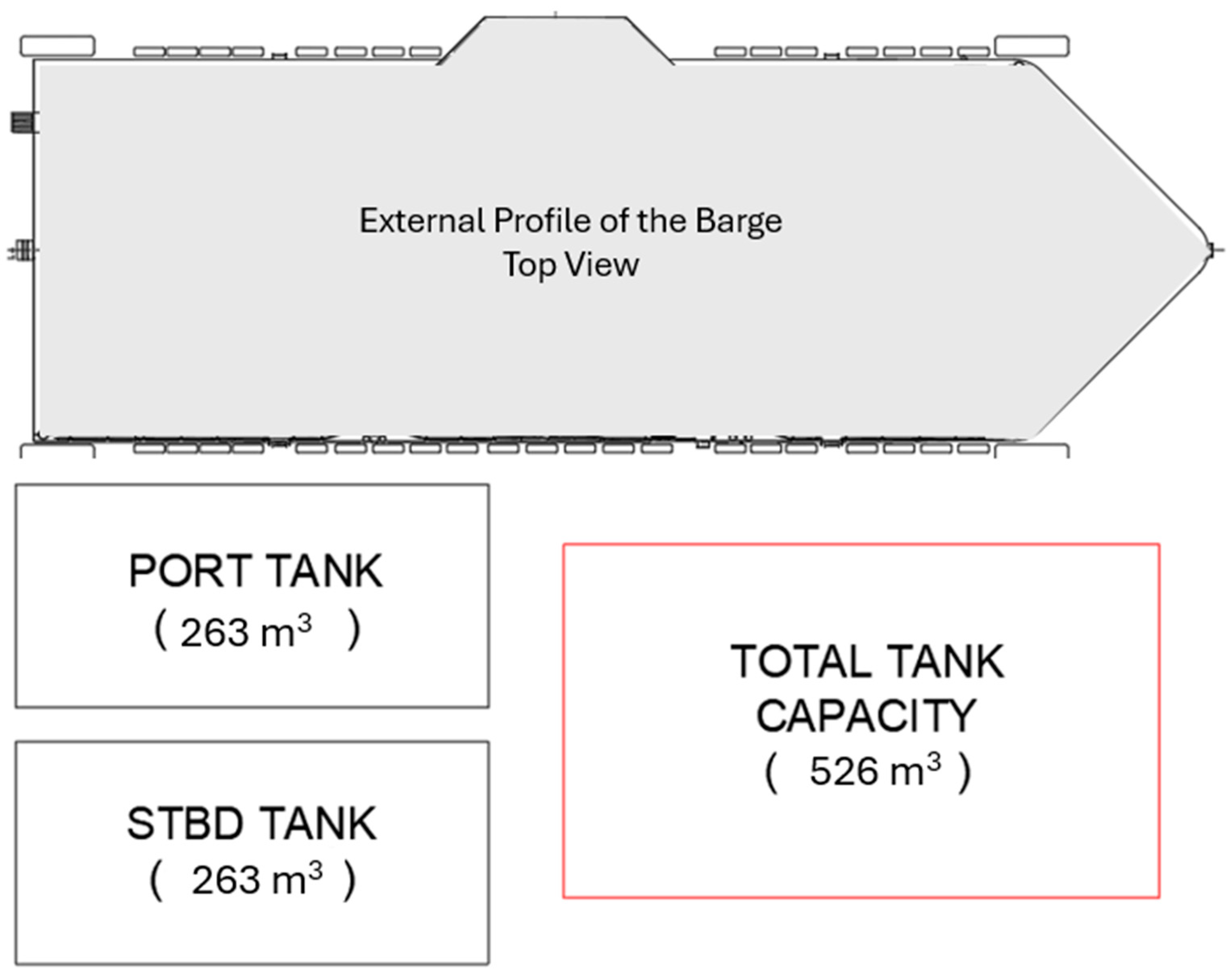
3, the barge stores approximately 1086.8 GJ of energy. This requires approximately 394 m
3 of 350 bar CH₂ to store 9.05 tonnes of hydrogen. Considering the CH
2 cylinders, the total estimated volume and weight increase to 526 m
3 and 178 tonnes, respectively (see the note for
Table 2), to achieve equivalent performance in terms of the bunkering requirements (to meet the energy demands). It prompts approximately 18.4 times the space demand and 6.8 times in weight compared to the conventional arrangement.
Accommodating this volume on the barge is infeasible due to spatial requirements along with the adverse effects on the vessel’s stability as a result of the drastic change in weight distribution. For simplicity, this study only focuses on the spatial requirements, assuming that stability challenges will be addressed by modifying the existing MDO fuel tanks to hold ballast. Referring to the theoretical tank dimensions provided in
Table 3,
Figure 1 provides a scaled visual representation of the hydrogen fuel tank area relative to the barge’s original design.
5.5. Feasibility Analysis of Fuel Requirements
Challenges associated with hydrogen storage stem primarily from hydrogen’s volumetric energy density. While the cylinders add weight, this can be effectively managed due to the fact that it is small compared to the weight of the barge. This section analyses the potential feasible solutions using the AM approach.
5.5.1. Altering Tank Arrangement
Although the fuel tank dimensions can be iterated and arranged in several ways, it is important to note that each method will have its own limitations. Ultimately, for the barge, the spatial requirements to accommodate the required fuel capacity (for equivalent performance) cannot be altered unless bunkering frequency is increased.
Table 4 presents various onboard CH
2 storage cases.
5.5.2. Frequent Bunkering
Achieving the same seven-day bunkering frequency (for equivalent performance) is infeasible for the HFV. More frequent bunkering could mitigate spatial constraints. The barge consumes approximately 4 m
3 of MDO per day (155.3 GJ/day). Assuming similar energy losses in the powering, auxiliary, and feed systems of the HFV [
47], the HFV would require approximately 56 m
3 (1.3 tons) of 350 bar CH
2 per day. This infers that the HFV would prompt almost double the fuel capacity (volume) requirement for a single day that the barge currently utilises for the entire seven-day bunkering schedule.
5.5.3. Cost Risk and Performance Compromise Due to Frequent Bunkering
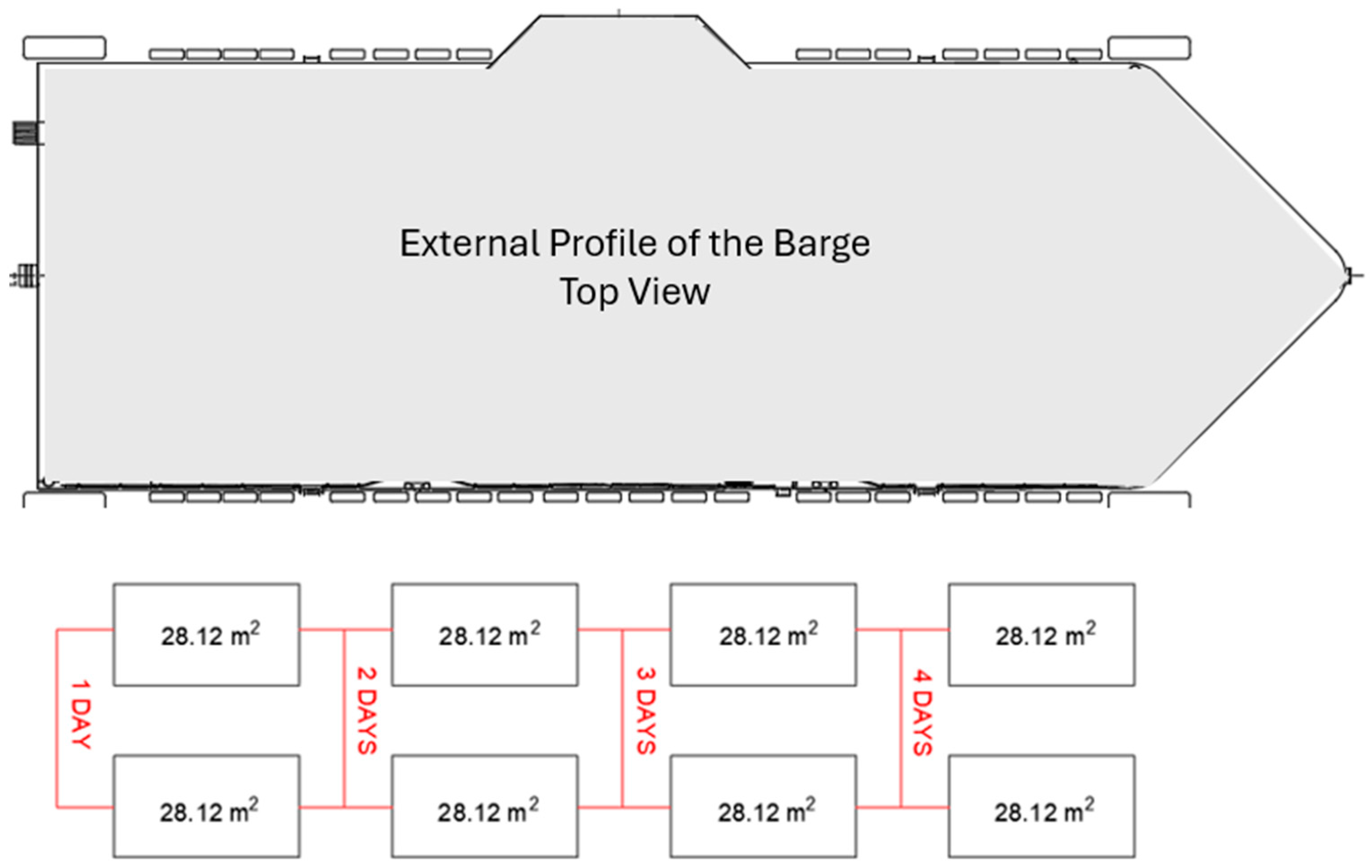
Figure 2 and
Table 5 indicate that a bunkering frequency beyond three days is infeasible due to spatial constraints. Achieving a bunkering frequency beyond one to two days would prompt several considerations with regard to the redesign, extensive risk assessments, and class review for approval.
Section 4 suggests that even a two-day bunkering schedule is highly unlikely due to risks associated with tank arrangements and associated systems.
Table 6 provides a breakdown for the cost, risk, and performance compromise of the most feasible one- to two-day bunkering frequency scenarios (Cases 1, 3, and 10) from
Table 4.
Among the defined cases, Case 10 is the most feasible option for hydrogen storage and bunkering. Although establishing a floating bunkering platform entails high costs, it is an adaptable solution to the evolving green hydrogen industry. Such a platform could serve other potential hydrogen-powered vessels in the region and can potentially store higher pressure CH2 gas or even LH2 as infrastructure develops. Additionally, the proposed Bell Bay H2 hub could supplement supply, reducing reliance on the Mornington station, which would otherwise require significant expansion. Ultimately, the floating platform may provide a reasonable return on investment. The risk and performance limitations mainly stem from the environmental conditions, which can be address by utilising motion control and operating in areas with acceptable sea states. Overall, Case 10 presents a relatively positive asset management value balance with minimal cost and risk compromise while maximising performance output.
5.6. Fuel Cell System
Proton Exchange Membrane Fuel Cells (PEMFCs) are widely used in maritime applications due to their high technology readiness level [
5] and are therefore considered in this investigation.
5.6.1. Determining Fuel Cell Requirements
It is assumed that the efficiency of the powering, auxiliary, and feed systems of the HFV are mostly equal to the conventional vessel [
47]. Thus, the HFV requires an installed power of at least 900 kW to match the barge’s powering demands for systems such as feed distribution, barge-to-pen delivery, water circulation and aeration, lighting and environment control, and winches and cranes.
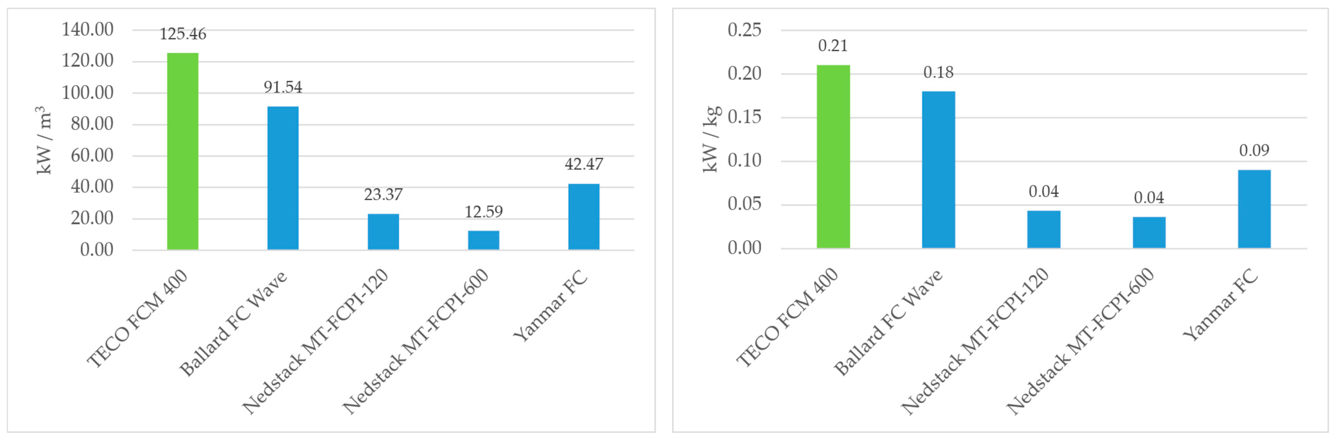
Table 7 provides specifications for suitable FC modules operating on CH
2 from four different manufacturers. To account for unideal operating conditions, a 10% loss in efficiency is considered for every module. The FCs are selected based on the power-to-weight and power-to-volume ratios to consider the most efficient power delivery system with regard to weight and spatial requirements.
As shown in
Figure 3, the most optimal configuration consists of four TECO FCM 400 units, providing 1170 kW of power at an occupied volume of 9.33 m
3. Although this exceeds the minimum power requirements, it is still considered suitable since it occupies less volume and has a relatively smaller deviation in weight from the barge. This will ensure that there are considerably less adverse effects on the vessel’s stability as a result of weight reduction/increase from the powering system. As per the classification requirements, a single failure of a FC power installation shall not lead to an unacceptable loss of power [
39]; therefore, the additional power is considered favourable as it allows for greater redundancy. It should be noted that the Ballard FC Wave stack is also fit for purposes of this vessel in terms of the power, weight, and occupied volume. For additional power demands, the batteries can be employed to provide a hybrid power supply system.
5.6.2. Fuel Cell Availability
FC stacks need to be replaced several times throughout the vessel’s lifecycle. Therefore, it is important to account for this in the retrofit design and to consider the logistics of procuring the relevant parts and components. On average, each FC module shown in
Table 8 has a maximum lifetime of approximately 30,000 h. TECO 2030 and Nedstack are based in Europe, Ballard in North America and Yanmar in Japan. However, each manufacturer has suppliers based in Australia expect for Ballard. Nonetheless, the replacement of these FC stacks is not time-critical and allows for sufficient opportunity to plan the logistics of such undertakings well in advance. One of the biggest considerations in retrofitting from conventional ICEs to FCs is the replacement planning of the FC stack throughout the vessel’s lifecycle. It is crucial to develop an efficient method for replacing the FC stacks during the design stage of the retrofit to ensure that the compromise on cost, risk, and performance is minimised. A poorly designed replacement plan could incur additional costs due to extensive labour, extra materials, and additional time. This can also increase the risk of not meeting the vessel’s commercial goals amongst the risks that may be presented during replacement operations. The performance of the vessel is measured by its efficiency in undertaking its intended operations and meeting its commercial goals. Thus, the replacement process should be well planned to minimise the time that the vessel is out of service.
5.7. Battery Installation
Li-Po batteries offer exceptional safety and flexibility, making them quite desirable in maritime applications. Nevertheless, this study considers Li-ion batteries due to their relatively high depth of discharge, advanced technology, and availability at reduced costs.
5.7.1. Determining Energy Storage System Requirements
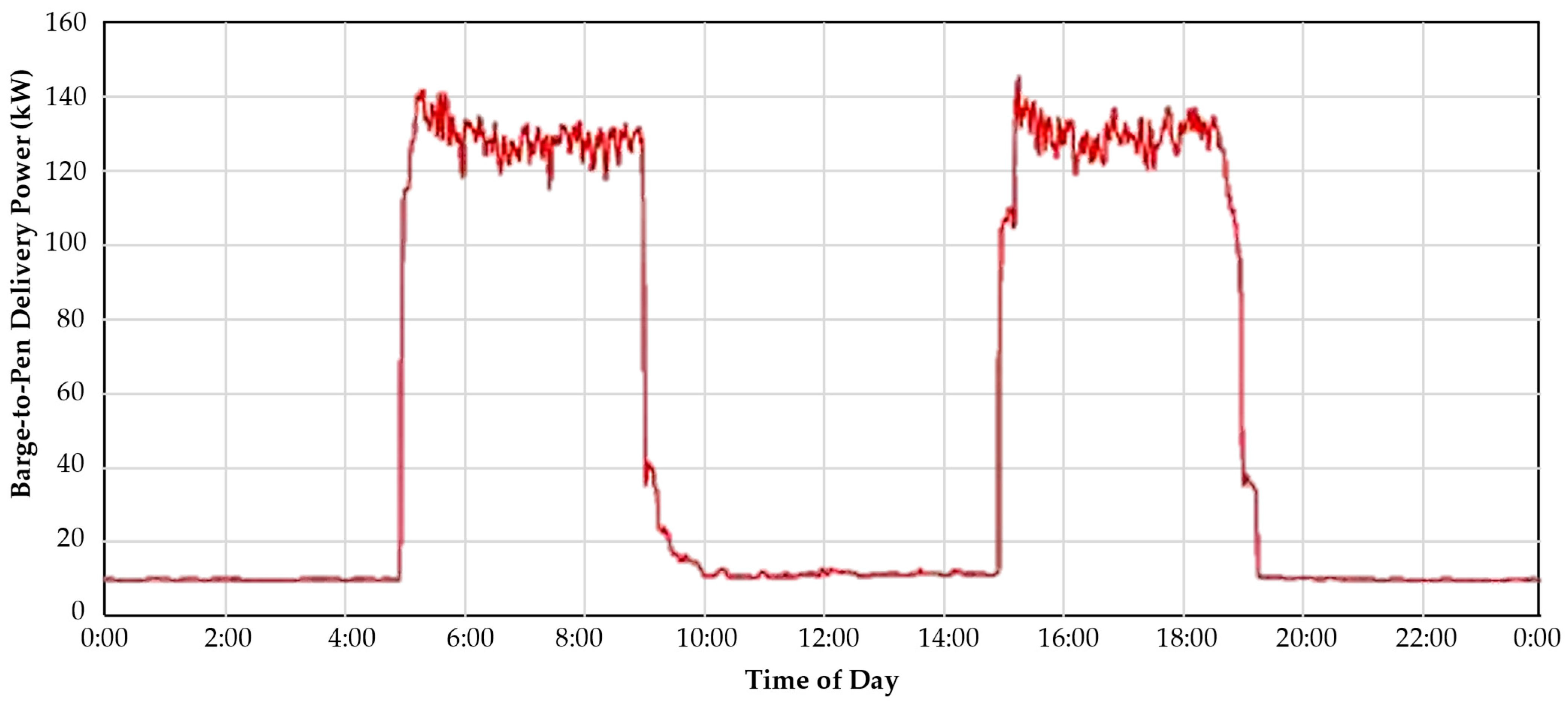
The estimate for the energy requirement of the ESS is obtained using the barge-to-pen feed delivery powering data of a similar vessel (refer to
Figure 4). The power demand is at its highest during feed delivery operations, which occur twice a day for approximately four hours per cycle. The requirements for these operations can be satisfied using energy generated from FCs. However, the ESS stores additional energy generated by the FCs to provide hybrid power during load variations, powers some onboard auxiliary systems during bunkering operations, and/or meets the powering requirements in the case of a failure of the FC power installations. In accordance with the data provide in
Figure 4 and the information establish in previous sections, the energy storage system was selected to have a rated energy of 300 kWh, which can cover two-hour barge-to-pen delivery operations.
5.7.2. ESS Availability
This study considers three units of the 100 kWh ESS from QH Technology, a high voltage battery producer.
Table 8 presents the specifications of the ESS. These batteries are subject to replacement throughout the vessel’s lifecycle. Therefore, it is crucial to account for the replacement plans in the retrofit design and pay special consideration to the logistics of procurement and installation.
5.8. Powering Specifications
As justified in
Section 5.6 and
Section 5.7,
Table 9 provides specifications for the HFV powering requirements (for equivalent performance) in comparison with the conventional feed barge specifications.
6. Feasibility of Hydrogen Retrofitting in Australia
Significant costs are associated with retrofit design and production of boats/ships, as several systems within the vessel must be removed and replaced with HFV-associated systems. Depending upon the size of the vessel, the complexity of the systems, the available infrastructure in the operational region, and the design changes required for the retrofit, the cost can increase significantly, which may make retrofitting an unfeasible option. Ultimately, this can favour new builds, as they may provide a better asset management value balance.
The current Australian shipbuilding market does not encourage new-build vessels for commercial use due to the high labour costs compared to other countries. Australia is also relatively stricter with class certifications, as AMSA requires classification compliance for novel vessels operating in Australian waters [
53]. In contrast, many other countries do not impose this requirement for vessels under 50 m in length. Extensive risk analysis is often required to acquire class approval, and with the relatively lower knowledge bandwidth of HFV design and production (as there is no established framework for the design and production of HFV), this can greatly increase costs, leading clients to avoid class certification where practicable.
To meet Australia’s commitment to the Paris Agreement, it is inevitable for considering retrofitting the existing fleet of vessels. The case study presented in
Section 5 demonstrates that hydrogen retrofitting may not always be feasible on a case-by-case basis, from both a technical and commercial perspective. This is primarily due to the cost, risk, and performance compromise, particularly given the current infrastructure in Australia and the available technology. Nonetheless, it is important to note that this case study only provides one of many potential applications where a hydrogen retrofit may be considered. The approach utilised in this study can be adopted to identifying determining factors, and areas of improvement must be addressed to make hydrogen retrofitting feasible in Australia.
7. Conclusions
The case study identifies the determining factors for a feasible hydrogen retrofit application with respect to an asset management approach. It provides an overview of the challenges associated with the design, production, and operations of an HFV, defines considerations to classification society requirements, and analyses the feasibility of achieving equivalent performance. The main challenge in developing a retrofit design is achieving equivalent performance while minimising cost and risk. This is primarily due to the low volumetric energy density of hydrogen, which prompts more frequent bunkering, ultimately resulting in the vessel spending much less time conducting its intended operations and incurring higher associated costs and risks. A negative AMV balance is introduced as a result. However, these challenges can be overcome by developing more advanced hydrogen infrastructures in operational regions and setting standards for the use of hydrogen in maritime applications. For example, standardising a minimum of 700 bar CH2 for CH2 bunkering stations, as the volumetric energy density at 350 bar is too low for feasible maritime applications. Additionally, advancement in cryogenic CH2 and LH2 applications should also be pursued to standardise its use over current methods.
In conclusion, the feasibility of retrofitting conventional vessels with hydrogen power is heavily dependent on the infrastructure that is presented. The infrastructure must address the spatial challenges (explored throughout this paper) associated with the storage of hydrogen on vessels, by providing more energy-dense hydrogen fuels and developing standards and procedures to make bunkering operations more efficient (to minimise the time spent bunkering).
Table 10 presents a comparison of the spatial requirements for storing hydrogen of varying physical properties, which highlights the importance for further infrastructure developments required to make hydrogen retrofitting feasible. Nonetheless, it should be noted that cryogenic fuels may require additional space, such as fuel preparation rooms for associated systems. Ultimately, all vessels are purpose-built and differ from one another; therefore, the required infrastructure —in terms of the facilities and locations—must also be designed and developed to support these intended purposes. To put this in perspective, the case study presented in this paper would be considered much more feasible if there were an LH
2 or cryo-compressed H
2 [
54] bunkering facility nearby, provided on a floating facility within the operational zone.
8. Limitations and Future Works
This paper does not consider the detailed design for the retrofit, including the extensive risk assessments required to justify design decisions such as the arrangement of tanks, FCs, batteries, and their associated systems. Thus, several technical aspects of a retrofit design are not discussed. A major example of this is the lack of consideration for the vessel’s stability. Hydrogen retrofitting would drastically reduce the initial fuel weight, while the MDO fuel tanks located on either side of the vessel will become voids. The resulting change in weight distribution will have adverse effects on the hydrostatics of the vessel, potentially leading to variations in the resistance curves, load lines, seakeeping, and most importantly, the stability. To address this, the fuel tanks may be used as seawater ballast (which is not ideal, as the vessel would effectively be carrying non-essential cargo, making it inefficient and perhaps less “green”) or converted into silos for the feed tanks. However, there are various technical considerations associated with this.
For hydrogen storage, this study focused on 350 bar CH
2. As advancements are made in various storage methods, including physical-, chemical- [
55], and material-based methods [
56], these hydrogen storage technologies can be compared to identify optimal solutions.
Individual case studies, such as the one provided in this paper, can be performed using an asset management approach to build a portfolio of feasibility studies, which could aid in developing feasibility criteria. This will help to identify the determining factors that need to be addressed for a given retrofit application. Additionally, hybrid power systems could be considered to investigate whether they can provide a more reasonable asset management value balance by reducing bunkering frequency.
Author Contributions
Conceptualization, M.W.Y.K. and H.F.; methodology, M.W.Y.K.; software, M.W.Y.K.; validation, M.W.Y.K. and H.F.; formal analysis, M.W.Y.K.; investigation, M.W.Y.K.; resources, M.W.Y.K. and H.F.; data curation, M.W.Y.K.; writing—original draft preparation, M.W.Y.K.; writing—review and editing, H.F.; visualisation, M.W.Y.K.; supervision, H.F.; project administration, M.W.Y.K. All authors have read and agreed to the published version of the manuscript.
Funding
This research did not receive external funding.
Data Availability Statement
The data that support the findings of this study are available from the corresponding author upon reasonable request.
Acknowledgments
The authors extend their sincere gratitude to Saeed Mohajernasab for his invaluable guidance and supervision and to Nagi Abdussamie for his insightful advice during the initial stages of this project. Additionally, the authors would like to express their appreciation to Sammar Abbas for his significant contributions to the development of the asset management (AM) methodologies employed in the feasibility studies.
Conflicts of Interest
The authors declare no conflict of interest.
Abbreviations
| ABS | American Bureau of Shipping |
| AM | Asset management |
| AMSA | The Australian Maritime Safety Authority |
| AMV | Asset management value |
| BV | Bureau Veritas |
| CCS | China Classification Society |
| CH2 | Compressed hydrogen gas |
| DCV | domestic commercial vessel |
| DNV | Det Norske Veritas |
| ESS | Energy storage system |
| FC | Fuel cell |
| FMECA | Failure Modes, Effects, and Criticality Analysis |
| GHG | Greenhouse gas |
| GVU | Gas valve unit |
| H2 | Hydrogen gas |
| HAZID | Hazard Identification |
| HAZOP | Hazard and Operability Studies |
| HFV | Hydrogen-fuelled vessel |
| ICE | Internal combustion engine |
| IGF Code | The International Code of Safety for Ships Using Gases or Other Low-flashpoint Fuels |
| IMO | The International Maritime Organization |
| KR | Korean Register of Shipping |
| LEL | Lower explosive limit |
| LETS | Low Emissions Technology Statements |
| LH2 | Cryogenic liquid hydrogen |
| Li-ion | Lithium-ion |
| LiPo | Lithium-polymer |
| LR | Lloyd’s Register |
| MDO | Marine disesel oil |
| MEPC | Marine Environment Protection Committee |
| PEM | Proton Exchange Membrane |
| RINA | Registro Italiano Navale (Italian Naval Register) |
| SOLAS | The International Convention for the Safety of Life at Sea |
References
- IMO. Reduction of GHG Emissions from Ships—Fourth IMO GHG Study 2020—Final Report. Available online: https://imoarcticsummit.org/wp-content/uploads/2020/09/MEPC-75-7-15-Fourth-IMO-GHG-Study-2020-Final-report-Secretariat.pdf (accessed on 20 December 2024).
- IMO. International Maritime Organization (IMO) Adopts Revised Strategy to Reduce Greenhouse Gas Emissions from International Shipping. Available online: https://www.imo.org/en/MediaCentre/PressBriefings/pages/Revised-GHG-reduction-strategy-for-global-shipping-adopted-.aspx (accessed on 20 December 2024).
- United Nations. The Paris Agreement. Available online: https://www.un.org/en/climatechange/paris-agreement (accessed on 6 February 2025).
- Australian Government. Australia’s Long-Term Emissions Reduction Plan. Available online: https://www.dcceew.gov.au/climate-change/publications/australias-long-term-emissions-reduction-plan (accessed on 22 December 2024).
- Fan, H.; Abdussamie, N.; Harris, A.; Chen, P.S.-L.; Gray, E.; Arzaghi, E.; Bhaskar, P.; Mehr, J.A.; Penesis, I. A Review of the Feasibility of Utilising Hydrogen as a Marine Fuel in Australia; Blue Economy Cooperative Research Centre: Launceston, Australia, 2023. [Google Scholar]
- Wang, H.; Boulougouris, E.; Theotokatos, G.; Zhou, P.; Priftis, A.; Shi, G. Life cycle analysis and cost assessment of a battery powered ferry. Ocean Eng. 2021, 241, 110029. [Google Scholar] [CrossRef]
- Kondratenko, A.A.; Zhang, M.; Tavakoli, S.; Altarriba, E.; Hirdaris, S. Existing technologies and scientific advancements to decarbonize shipping by retrofitting. Renew. Sustain. Energy Rev. 2025, 212, 115430. [Google Scholar] [CrossRef]
- Guan, W.; Chen, L.; Wang, Z.; Chen, J.; Ye, Q.; Fan, H. A 500 kW hydrogen fuel cell-powered vessel: From concept to sailing. Int. J. Hydrogen Energy 2024, 89, 1466–1481. [Google Scholar] [CrossRef]
- Pal, N.; Boudreau, B.; Monroe, N.; Vaughn, E.; Zaag, N.; Sookhoo, R.; Harris, K.; Vogel, B.; Klebanoff, L.E. Project Nautilus: Introducing a hydrogen fuel cell system as a retrofit for a hybrid electric vessel. Int. J. Hydrogen Energy 2024, 53, 1457–1476. [Google Scholar] [CrossRef]
- Wang, Z.; Dong, B.; Yin, J.; Li, M.; Ji, Y.; Han, F. Towards a marine green power system architecture: Integrating hydrogen and ammonia as zero-carbon fuels for sustainable shipping. Int. J. Hydrogen Energy 2024, 50, 1069–1087. [Google Scholar] [CrossRef]
- Huang, J.; Fan, H.; Xu, X.; Liu, Z. Life Cycle Greenhouse Gas Emission Assessment for Using Alternative Marine Fuels: A Very Large Crude Carrier (VLCC) Case Study. J. Mar. Sci. Eng. 2022, 10, 1969. [Google Scholar] [CrossRef]
- Fan, H.; Enshaei, H.; Jayasinghe, S.G.; Tan, S.H.; Zhang, C. Quantitative risk assessment for ammonia ship-to-ship bunkering based on Bayesian network. Process Saf. Prog. 2022, 41, 395–410. [Google Scholar] [CrossRef]
- de-Troya, J.J.; Álvarez, C.; Fernández-Garrido, C.; Carral, L. Analysing the possibilities of using fuel cells in ships. Int. J. Hydrogen Energy 2016, 41, 2853–2866. [Google Scholar] [CrossRef]
- Latapí, M.; Davíðsdóttir, B.; Jóhannsdóttir, L. Drivers and barriers for the large-scale adoption of hydrogen fuel cells by Nordic shipping companies. Int. J. Hydrogen Energy 2023, 48, 6099–6119. [Google Scholar] [CrossRef]
- SGMF. Hydrogen as a Marine Fuel: An Introduction. Available online: https://safety4sea.com/wp-content/uploads/2023/02/SGMF-Hydrogen-as-a-marine-fuel-2023_02.pdf (accessed on 20 December 2024).
- ARENA. Australia’s Pathway to $2 per kg Hydrogen. Available online: https://arena.gov.au/blog/australias-pathway-to-2-per-kg-hydrogen/ (accessed on 19 December 2024).
- Abbas, S. Evaluating and Visualising the Balance of Cost, Risk, and Performance in Asset Management. Available online: https://www.amcouncil.com.au/event/webinar-asc-evaluating-and-visualising-the-balance-of-cost-risk-and-performance-am-in-action-a-2024-excellence-award-submission/ (accessed on 5 November 2024).
- ISO 31000:2018; International Organization for Standardization. Risk management—Guidelines. International Organization for Standardization: Geneva, Switzerland, 2018.
- Melideo, D.; Desideri, U. The use of hydrogen as alternative fuel for ship propulsion: A case study of full and partial retrofitting of roll-on/roll-off vessels for short distance routes. Int. J. Hydrogen Energy 2024, 50, 1045–1055. [Google Scholar] [CrossRef]
- McKinlay, C.J.; Turnock, S.R.; Hudson, D.A.; Manias, P. Hydrogen as a deep sea shipping fuel: Modelling the volume requirements. Int. J. Hydrogen Energy 2024, 69, 863–873. [Google Scholar] [CrossRef]
- Decarbonizing Bulk Carriers with Hydrogen Fuel Cells and Wind-Assisted Propulsion: A Modeled Case Study Analysis. Available online: https://theicct.org/wp-content/uploads/2022/01/Hydrogen-and-propulsion-ships-jan22.pdf (accessed on 20 December 2024).
- Verfondern, K. Chapter 1—Hydrogen fundamentals. In Hydrogen Safety for Energy Applications; Kotchourko, A., Jordan, T., Eds.; Butterworth-Heinemann: Oxford, UK, 2022; pp. 1–23. [Google Scholar] [CrossRef]
- Chen, P.S.-L.; Fan, H.; Enshaei, H.; Zhang, W.; Shi, W.; Abdussamie, N.; Miwa, T.; Qu, Z.; Yang, Z. A review on ports’ readiness to facilitate international hydrogen trade. Int. J. Hydrogen Energy 2023, 48, 17351–17369. [Google Scholar] [CrossRef]
- Pua, C.; Hu, P.; Ji, C.; Zhu, Z.; Zheng, B.; Zhai, S. Simulation analysis of protective wall against hydrogen combustion from liquified hydrogen storage tank on the offshore launching platform. Int. J. Hydrogen Energy 2023, 48, 12501–12518. [Google Scholar] [CrossRef]
- Elrhoul, D.; Romero Gómez, M.; Naveiro, M. Review of green hydrogen technologies application in maritime transport. Int. J. Green Energy 2023, 20, 1800–1825. [Google Scholar] [CrossRef]
- Chen, P.S.-L.; Fan, H.; Enshaei, H.; Zhang, W.; Shi, W.; Abdussamie, N.; Miwa, T.; Qu, Z.; Yang, Z. Opportunities and Challenges of Hydrogen Ports: An Empirical Study in Australia and Japan. Hydrogen 2024, 5, 436–458. [Google Scholar] [CrossRef]
- CSIRO. HyResource. 2024. Available online: https://research.csiro.au/hyresource/ (accessed on 10 December 2024).
- Fan, H.; Abdussamie, N.; Harris, A.; Chen, P.S.-L.; Gray, E.; Arzaghi, E.; Bhaskar, P.; Mehr, J.A.; Penesis, I. Feasibility study of adopting hydrogen fuel cells for Australian ships. In Proceedings of the IMC 2023 International Maritime Conference, Sydney, Australia, 7–9 November 2023. [Google Scholar]
- Venkatasetty, H.V.; Jeong, Y.U. Recent advances in lithium-ion and lithium-polymer batteries. In Proceedings of the Seventeenth Annual Battery Conference on Applications and Advances. Proceedings of Conference (Cat. No.02TH8576), Long Beach, CA, USA, 18 January 2002; pp. 173–178. [Google Scholar]
- Georgopoulou, C.; Di Maria, C.; Di Ilio, G.; Cigolotti, V.; Minutillo, M.; Rossi, M.; Sullivan, B.P.; Bionda, A.; Rautanen, M.; Ponzini, R.; et al. On the identification of regulatory gaps for hydrogen as maritime fuel. Sustain. Energy Technol. Assess. 2025, 75, 104224. [Google Scholar] [CrossRef]
- DNV. Handbook for Hydrogen-Fuelled Vessels; DNV: Bærum, Norway, 2021; Available online: https://www.iims.org.uk/wp-content/uploads/2021/07/Handbook_for_hydrogen-fuelled_vessels.pdf (accessed on 20 December 2024).
- IMO. MSC.1/Circ.1647 Interim Guidelines for the Safety of Ships Using Fuel Cell Power Installations; IMO: London, UK, 2022. [Google Scholar]
- IMO. The International Code of Safety for Ships Using Gases or Other Low-Flashpoint Fuels (IGF Code), Resolution MSC.391(95) Adopted on 19 June 2015; International Maritime Organization: London, UK, 2015. [Google Scholar]
- IMO. Revised Guidelines on Alternative Design and Arrangements for Solas Chapters II-1 and III; IMO: London, UK, 2024; Volume MSC.1/Circ.1212/Rev.2. [Google Scholar]
- IMO. Sub-Committee on Carriage of Cargoes and Containers, 10th Session (CCC 10), 16–20 September 2024. Available online: https://www.imo.org/en/MediaCentre/MeetingSummaries/Pages/ccc-10th-session.aspx (accessed on 15 October 2024).
- ABS. Requirements for Hydrogen Fueled Vessles. Available online: https://ww2.eagle.org/content/dam/eagle/rules-and-guides/current/other/338-requirements-for-hydrogen-fueled-vessels/338-hydrogen-fueled-vessel-reqts-may23.pdf (accessed on 20 December 2024).
- BV. NR678 Hydrogen-Fuelled Ships. Available online: https://erules.veristar.com/dy/data/bv/pdf/678-NR_2023-11.pdf (accessed on 20 December 2024).
- CCS. Guidelines for Ships Using Alternative Fuels. Available online: https://www.methanol.org/wp-content/uploads/2018/03/Guidelines-for-Ships-Using-Alternative-Fuels-Part-1.pdf (accessed on 20 December 2024).
- DNV. DNV Rules: Part 6 Chapter 2 Section 3 Fuel Cell Installations. Available online: https://static1.squarespace.com/static/5f0d42f16639a745affd633e/t/5ff5d082add77853459846ec/1609945229408/DNVGL-RU-SHIP-Pt6Ch2.pdf (accessed on 20 December 2024).
- KR. Guidance for Fuel Cell Systems on Board of Ships. Available online: https://www.krs.co.kr/KRRules/KRRules2024/data/DATA_OTHER/ENGLISH/Guidance%20for%20Fuel%20Cell%20Systems%20on%20Board%20Ships_2024.pdf (accessed on 20 December 2024).
- LR. Rules and Regulations for the Classification of Ships Using Gases or Other Low-Flashpoint Fuels, Appendix LR3—Requirements for Ships Using Hydrogen as Fuel; LR: London, UK, 2023. [Google Scholar]
- RINA. Rules of Safety for Ships Using Hydrogen as a Fuel. Available online: http://www.enrstandards.org/it/files/ENR_14002_31012023.pdf (accessed on 20 December 2024).
- Australian Government. Performance of Recognised Organisations. Available online: https://www.amsa.gov.au/recognised-organisation-performance (accessed on 29 January 2025).
- Fan, H.; Abdussamie, N.; Harris, A.; Chen, P.S.-L. Numerical investigation of hydrogen fuel tank skid leakage on a hydrogen-powered vessel. In Proceedings of the 43rd International Conference on Ocean, Offshore and Arctic Engineering (OMAE2024), Singapore, 9–14 June 2024. [Google Scholar]
- Dadashzadeh, M.; Ahmad, A.; Khan, F. Dispersion modelling and analysis of hydrogen fuel gas released in an enclosed area: A CFD-based approach. Fuel 2016, 184, 192–201. [Google Scholar] [CrossRef]
- Australian Government. Hydrogen hub for Bell Bay, Tasmania. Available online: https://www.dcceew.gov.au/about/news/hydrogen-hub-for-bell-bay-tasmania (accessed on 28 May 2024).
- Ghosh, B. Chapter 6.1—Potential of hydrogen in powering mobility and grid sectors. In Towards Hydrogen Infrastructure; Jaiswal-Nagar, D., Dixit, V., Devasahayam, S., Eds.; Elsevier: Amsterdam, The Netherlands, 2024; pp. 349–376. [Google Scholar] [CrossRef]
- TECO 2030. TECO 2030 Fremtidens Hurtigbåt Hydrogen. Available online: https://hrf.no/wp-content/uploads/2024/10/5-TECO2030_hurtigbatkonferansen-2024-10-17.pdf (accessed on 9 November 2024).
- BALLARD. Fuel Cell Power Module for Marine Applications. Available online: https://www.ballard.com/wp-content/uploads/2024/11/FCwave_20241008.pdf (accessed on 20 December 2024).
- Nedstack. PemGen MT-FCPI-120. Available online: https://nedstack.com/en/pemgen-solutions/maritime-power-installations/pemgen-mt-fcpi-120 (accessed on 9 June 2023).
- Nedstack. PemGen MT-FCPI-600. Available online: https://nedstack.com/en/pemgen-solutions/maritime-power-installations/pemgen-mt-fcpi-600 (accessed on 9 June 2023).
- Yanmar. Yanmar to Commercialize Maritime Hydrogen Fuel Cell System to Decarbonize Ships. Available online: https://www.yanmar.com/global/marinecommercial/news/2023/08/01/127374.html (accessed on 29 August 2023).
- AMSA. Novel Vessel Policy Statement. Available online: https://www.amsa.gov.au/sites/default/files/2023-08/novel-vessel-policy-statement-june-2022.pdf (accessed on 20 December 2024).
- Amirthan, T.; Perera, M.S.A. The role of storage systems in hydrogen economy: A review. J. Nat. Gas Sci. Eng. 2022, 108, 104843. [Google Scholar] [CrossRef]
- Ship System Design Changes for the Transition to Hydrogen Carriers. Available online: https://sh2ipdrive.com/app/uploads/2024/08/T3.IMDC_2024_ComponentSizing-final.pdf (accessed on 20 December 2024).
- Hirscher, M.; Yartys, V.A.; Baricco, M.; Bellosta von Colbe, J.; Blanchard, D.; Bowman, R.C.; Broom, D.P.; Buckley, C.E.; Chang, F.; Chen, P.; et al. Materials for hydrogen-based energy storage—past, recent progress and future outlook. J. Alloys Compd. 2020, 827, 153548. [Google Scholar] [CrossRef]
| Disclaimer/Publisher’s Note: The statements, opinions and data contained in all publications are solely those of the individual author(s) and contributor(s) and not of MDPI and/or the editor(s). MDPI and/or the editor(s) disclaim responsibility for any injury to people or property resulting from any ideas, methods, instructions or products referred to in the content. |
© 2025 by the authors. Licensee MDPI, Basel, Switzerland. This article is an open access article distributed under the terms and conditions of the Creative Commons Attribution (CC BY) license (https://creativecommons.org/licenses/by/4.0/).


