1. Introduction
Hydrogen, as is widely acknowledged, serves as a crucial energy carrier, and its role in energy transition is intricately tied to its ability to store energy harnessed from renewable sources. There is significant emphasis on hydrogen and its relevance. However, the prevailing perception is that the debate tends to be overly general, initially encompassing broad elements while potentially overlooking some crucial technical aspects [
1]. The discussion about hydrogen has been ongoing for over 40 years, yet the lack of compelling solutions for widespread applications is still tied to certain technical aspects related to materials and intrinsic challenges related to hydrogen. Additionally, it is important to clarify that hydrogen is a carrier and as such needs to be integrated into an energy chain where energy balances must be respected, and the overall process efficiency must be high. The recent interest in hydrogen is primarily associated with its potential integration with the increasing penetration of renewable energy in energy systems. As outlined in
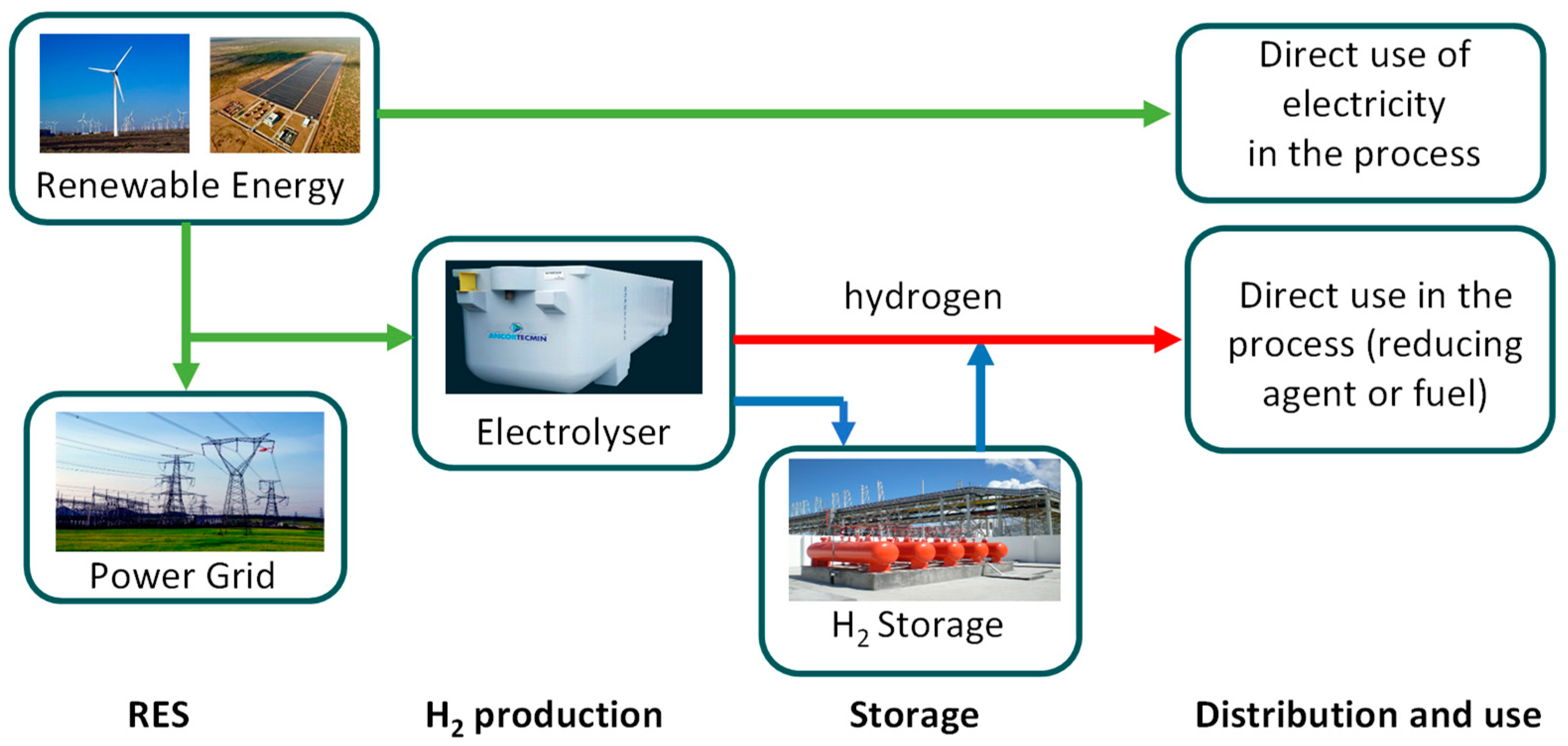
Figure 1, illustrating how hydrogen can be integrated into a system, hydrogen provides an additional opportunity to further incorporate renewable sources, especially intermittent ones like wind and photovoltaic (PV) solar.
Figure 1 illustrates, in a simplified manner, the potential integration of hydrogen in a specific industrial context, such as the steel sector, highlighting the significance of energy storage as well. The significance of hydrogen lies in its potential to facilitate load leveling in systems anticipating an escalating integration of intermittent or non-programmable renewable sources.
Hence, it has become imperative to address hydrogen storage in a comprehensive manner. Despite hydrogen’s high specific energy per unit mass, with 120 MJ/kg as the lower heating value (LHV), its low energy density per unit volume (about 10 MJ/m
3) presents a challenge for achieving compact, cost-effective, and secure energy-dense storage solutions. The subject of hydrogen storage has been under scrutiny for an extended period, leading to the proposition of various storage methods at different junctures. However, determining outright superiority among these methods remains elusive. Various storage methods exist, each with their own advantages and drawbacks, considering both cost and performance factors that depend on specific application requirements [
2].
Currently, there is no ideal storage technology for most applications. Storage methods fall into two categories: physical storage, where elemental hydrogen is stored, and materials-based storage, where hydrogen is bound within other materials. From a distinct perspective, hydrogen can be stored through three fundamental methods: compressed hydrogen gas (CGH
2), liquid hydrogen (LH
2), and the solid storage of hydrogen (SSH
2). The latter involves the modification of hydrogen’s physical state [
3].
Some recent papers have covered a spectrum of hydrogen-storage technologies, providing insights into their status, advancements, and the potential implications for a sustainable-energy future. Arsad et al. (2022), in [
4], explore the integration of hydrogen energy storage within hybrid renewable-energy systems. The review provides a comprehensive analysis of current research trends and discusses future directions for this field. Wieliczko and Stetson, in [
5], emphasize the importance of hydrogen as an energy carrier and discuss various technologies in this context. Usman, in [
6], presents a thorough review of hydrogen-storage methods and their statuses. The paper shows the strengths and limitations of different storage approaches. Hassan et al., in [
7], contribute to the discourse on the hydrogen energy future by focusing on advancements in storage technologies and their implications for sustainability. Muthukumar et al., in [
8], review the worldwide developmental status of large-scale hydrogen storage using various technologies such as compressed, cryogenic, ammonia, liquid organic hydrogen carrier, and solid-state hydrogen storage.
In the literature, it is possible to find mentions of electrochemical compression too. This is a promising method that utilizes electrochemical reactions to compress hydrogen gas and typically involves the use of proton exchange membrane (PEM) cells.
A theoretical advantage of electrochemical compression is its ability to achieve high compression ratios with low energy consumption compared to mechanical compression methods even if research in this area is ongoing. Despite electrochemical hydrogen compression being a promising field in theory, it is currently particularly challenging to consider it as a technology that could be available within a reasonable period.
Considering the more “conventional” methods, from the literature analysis, the conclusion drawn is that while each avenue can be considered, they all come with their own potentials and limitations, suggesting adaptability to specific contexts [
9].
The liquid storage of hydrogen is highly energy-intensive due to the energy requirements associated with the liquefaction process. The process of converting gaseous hydrogen into liquid hydrogen involves cooling the gas to extremely low temperatures, typically below −240 °C (in general −253 °C). Moreover, storing hydrogen in a liquid phase demands the maintenance of extremely low temperatures (hydrogen transitions to a liquid state at 20 K under atmospheric pressure). The storage of hydrogen in liquid form demands considerable energy and technologically advanced transportation infrastructure, making it suitable for transporting massive quantities of hydrogen over long distances but less feasible for smaller-scale solutions. The storage and transportation of liquid hydrogen demand specialized and well-insulated containers to maintain the low temperatures required. This adds to the complexity and cost of the infrastructure. The complexity of the infrastructure is not offset by a significant increase in hydrogen density, considering that at 1 bar and −253 °C, it is about 70 kg/m3.
When considering liquefied natural gas as a comparison, operating at a temperature of −162 °C, methane density is approximately 420 kg/m3, around 6 times higher than that of hydrogen. Consequently, from an energy standpoint, for an equal volume of the vessel, less than half the energy is transported, resulting in a ratio of approximately 5/2.
This energy requirement makes the overall hydrogen compression process less energy-efficient, also outlined in the paper by Zhang et al. [
10].
The challenges and energy costs associated with its compression, liquefaction, and storage make alternative compression methods, such as gaseous compression or solid-state storage, more attractive in certain applications.
Hydrogen storage through metal hydrides holds conceptual promise but introduces additional challenges related to material stability, rendering its practical use complex.
In general, the choice of storage method depends on several factors such as application, scale, infrastructure, and geographical considerations. For example, while high-pressure storage might be suitable for stationary applications with existing infrastructure, solid-state storage could be more advantageous for mobile applications due to its potentially higher energy density and safety.
High-density storage methods such as liquefaction or high-pressure compression can require significant energy input for both storage and transportation. This energy input must be considered when evaluating the overall efficiency and sustainability of hydrogen as an energy carrier. Recent developments and the anticipated widespread utilization of hydrogen suggest that, for several reasons, gaseous compression remains the most promising, especially for medium- and small-scale applications [
2]. Various technologies are employed for hydrogen compression, each with their own advantages and limitations. Some common hydrogen compression technologies include piston compressors and diaphragm compressors, used for small- and small-to-medium-scale application and screw compressors, which use rotating screws to compress hydrogen, as evidenced by Sdanghi et al. in [
11]. In the literature, the topic of compressing hydrogen in gaseous form has been extensively explored (Zheng et al. [
12]). Barthelemy, in [
13], provides a historical and technical overview of hydrogen-storage vessels discussing the challenges and constraints of hydrogen energy applications. The article explores the storage of hydrogen as a compressed or refrigerated liquefied gas, detailing the evolution of storage methods from seamless steel cylinders to aluminum cylinders and hoop-wrapped metallic cylinders. The development of fully wrapped composite tanks for high-pressure hydrogen storage is examined, along with the specific issues associated with these technologies. Ref. [
14] offers a synthetic analysis of hydrogen compression in gaseous form, focusing on recent advancements in efficiency, energy consumption reduction, and safety enhancement. Research efforts also aim to address challenges such as material compatibility, system reliability, and cost-effectiveness. Mechanical compression, including piston compressors, diaphragm compressors, and screw compressors, is a widely used method for achieving higher pressures. In a piston compressor, hydrogen gas is drawn into a cylinder and compressed by a reciprocating piston.
Performance in hydrogen compression is evaluated based on factors such as energy efficiency, compression ratio, and safety. Achieving high compression ratios is crucial for storage and transportation applications. However, it is essential to balance this with energy efficiency to minimize energy consumption. The prevalent choices are oriented to consider two pressure levels (350 bar or 700 bar), but a criterion for defining an optimal compromise among various process parameters is lacking. Research and development efforts continue to improve the efficiency and economics of hydrogen compression technologies. Innovations aim to address challenges such as heat management during compression to enhance overall performance. However, it is crucial to note that even with the widespread adoption of gaseous compression, the limited density of hydrogen at ambient conditions requires a push towards high pressures, typically exceeding 300 bar. The application of higher pressures brings thermodynamic advantages. An analysis of hydrogen’s thermophysical properties reveals that, at environmental temperature and 500 bar pressure, the hydrogen density is around 30 kg/m3—approximately 300 times higher than that in ambient conditions. The density further increases to about 50 kg/m3 under compression at 1000 bar. Nevertheless, the use of extremely high pressures introduces a myriad of challenges, necessitating the use of specialized materials with significant structural strength and resistance to embrittlement and incurring more substantial energy expenditure to meet specific requirements. This energy expenditure adds to a host of other factors, often rendering the hydrogen energy chain inefficient.
In addition to energy costs associated with the electrolysis phase, the substantial energy consumption during compression and end-use poses a risk of substantial reductions in overall process efficiencies. Despite the extensive history of dealing with hydrogen compression in gaseous form, identifying literature addressing the establishment of reasonable targets that strike a balance between various elements (compression work, storage system dimensions, physical characteristics, and associated costs) proves challenging. Hence, this work, following an in-depth analysis of the current state of gaseous hydrogen-storage methods, aims to outline criteria utilizing a multi-objective optimization approach, seeking to define optimized storage systems tailored to specific applications.
The study analyzes the compression of hydrogen in gaseous form, aiming to identify technological objectives with medium-term potential. It addresses material-related challenges, such as maximum temperature limits, and explores feasible technological solutions. Energy requirements and technological objectives are mainly evaluated considering that compressing H2 to high pressures results in a significant loss of its heating value, which impacts the overall operation.
The paper is motivated by the recognition that a comprehensive understanding of the storage phase, including its associated energy requirements and density considerations, is crucial for the successful integration of hydrogen into energy systems. This understanding will enable policymakers, researchers, and industry stakeholders to make informed decisions regarding the development and deployment of hydrogen technologies.
The paper is organized as follows.
Section 2 discusses the key thermophysical properties of hydrogen relevant to compression and outlines the storage requirements for gaseous hydrogen;
Section 3 gives a concise review of existing technological solutions for compressing gaseous hydrogen, examining their advantages and limitations.
Section 4 presents a compression model for analyzing energy requirements, including a sensitivity analysis to explore variations in parameters, while
Section 5 discusses the results of the compression analysis, comparing the actual compression work required for different combinations of initial and final pressure. The conclusion summarizes the key insights and implications for hydrogen compression technology and suggests areas for future research.
2. Thermophysical Properties of Hydrogen and Gas Compression Storage Requirements
Hydrogen stands out as an element renowned for its thoroughly documented thermophysical properties. Its allure lies in its energy potential, boasting a notably high lower calorific value of 120 MJ/kg; this promising energy carrier encounters a limitation in the form of its diminished density, particularly under atmospheric pressure conditions.
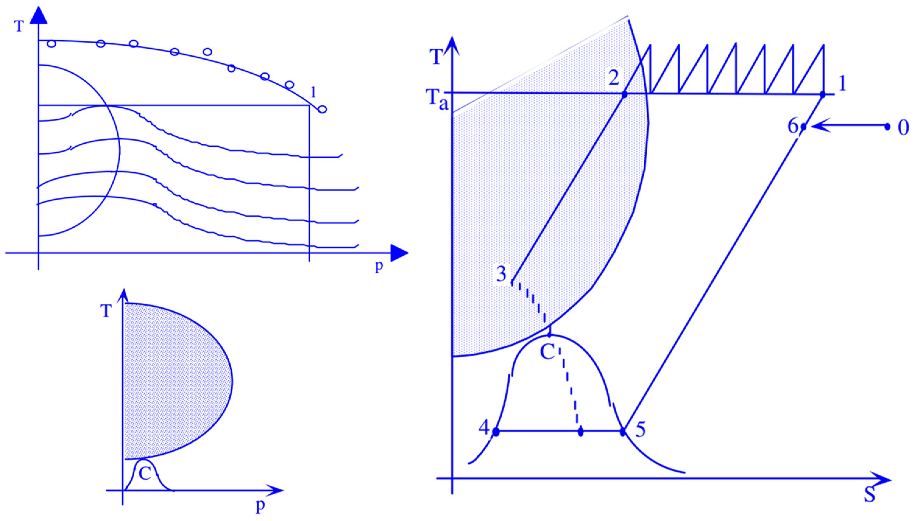
Table 1 shows a comparison of the volumetric energy densities of hydrogen with those of other gases typically used as fuels, such as natural gas and methane, under typical environmental conditions. From the analysis of hydrogen’s thermophysical properties, it is evident that gas-phase compression is thermodynamically advantageous. Liquid-phase compression, on the other hand, requires at least the same amount of work, but since the fraction of liquid separated is smaller, as depicted in the figure for a generic Linde compression cycle, a huge portion of the calorific power would be subtracted from the process. This is shown in a schematic way in
Figure 2.
Thinking about a generic gas like hydrogen, there is a zone in the
T-
p diagram, where the Joule–Thomson coefficient,
μ, which represents the derivative of temperature with respect to pressureis positive, while keeping enthalpy constant:
It represents the rate of change in temperature with respect to pressure for a fluid undergoing throttling or expansion without external work or heat transfer. This allows for the possibility of liquefying a gas through a simple expansion or, better, throttling. Indeed, if the
μ coefficient is negative, then decreasing the pressure increases the temperature, whereas if
μ is positive, decreasing the pressure in the expansion or throttling of Joule–Thomson also decreases the gas temperature, enabling its liquefaction. In the case of hydrogen, the zone of saturated vapors is well below the inversion zone (
Figure 2).
So, it is necessary to both compress and cool the fluid to be liquefied. In
Figure 2, a liquefaction process based on the Joule–Thomson effect is represented. As well evidenced in
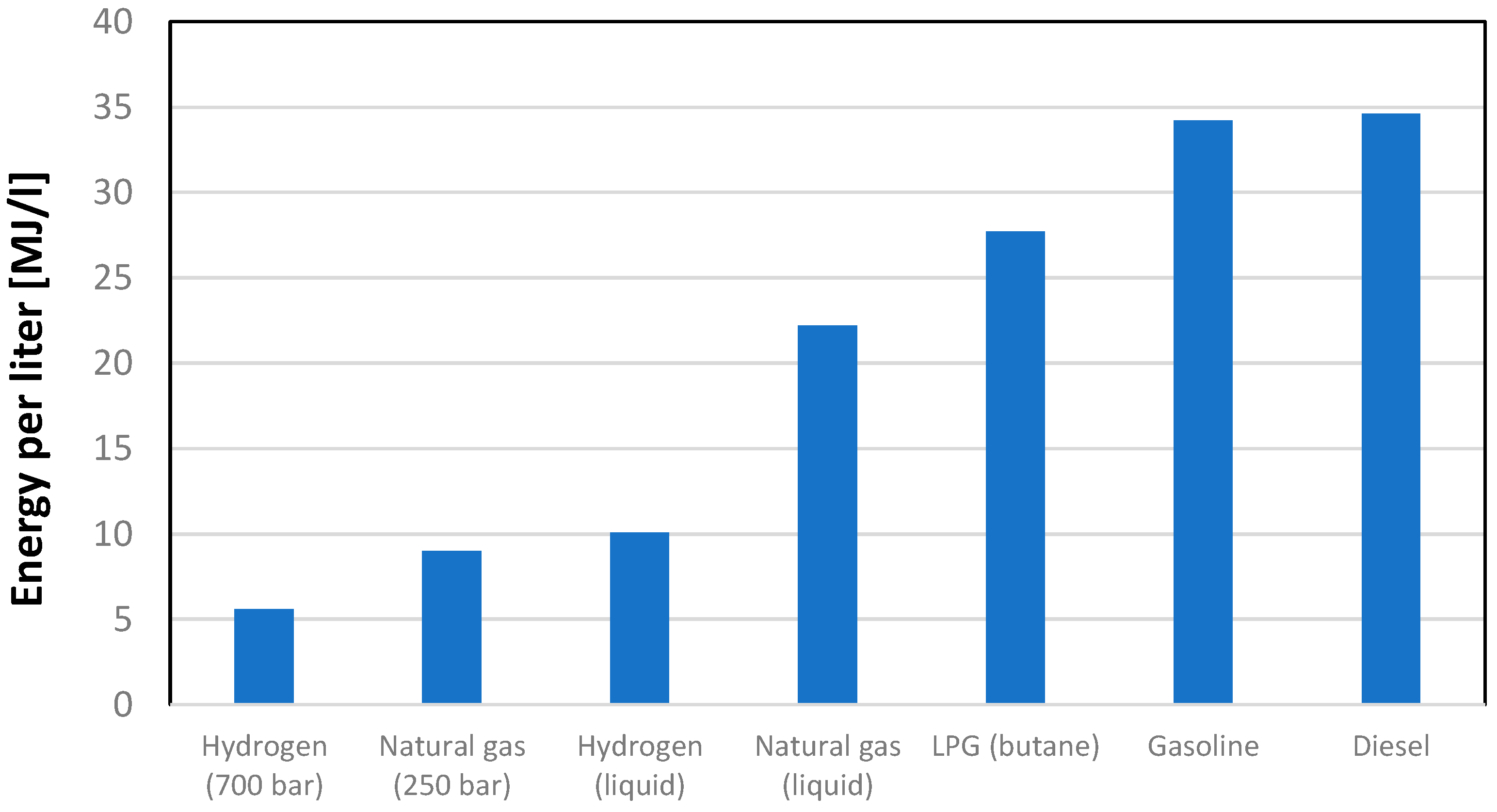
Figure 2, this not only involves significant energy requirement but also results in the separation of a small portion of hydrogen in liquid form, making it clear how compression in the liquid phase is unlikely to be a convenient solution, mainly from an energy point of view. In general, whether one wants to store hydrogen in liquid form or in gaseous form, it will be necessary to significantly increase the gas pressure, which will allow for a significant increase in density. The thermophysical properties of hydrogen are quite disadvantageous, although even high-pressure gas compression and liquefaction bring them closer to conventional fuels, albeit still at a certain distance. As can be observed from an analysis of
Figure 3, the volumetric energy content of hydrogen expressed in MJ/L, even with a compression level of 700 bar, is still about 1/7 of that available with the main liquid fuels typically used in the energy sector. Even liquefaction, despite all the highlighted issues, does not solve the problem. The issue of compressing hydrogen in gaseous form encompasses various aspects, including the significant consideration of storage vessels. Historically, certain pressure levels, such as 350 bar and 700 bar, have been identified as structurally feasible, with four distinct types of containers available for storage.
To compress the gas, multi-stage compression is typically employed. However, this compression transformation does not occur adiabatically because it would result in remarkably high energy consumption. For this reason, compression is conducted in multiple stages, and between each stage, the hydrogen must be adequately cooled.
To better understand the issues associated with hydrogen compression, whether aimed at maintaining it in liquid or gaseous conditions, it is necessary to have a clear idea of the orders of magnitude associated with the two phases. The thermophysical properties of hydrogen can be found in several books and articles such as [
15,
16], as well as in the NIST webbook database [
17].
Some relevant values are reported in
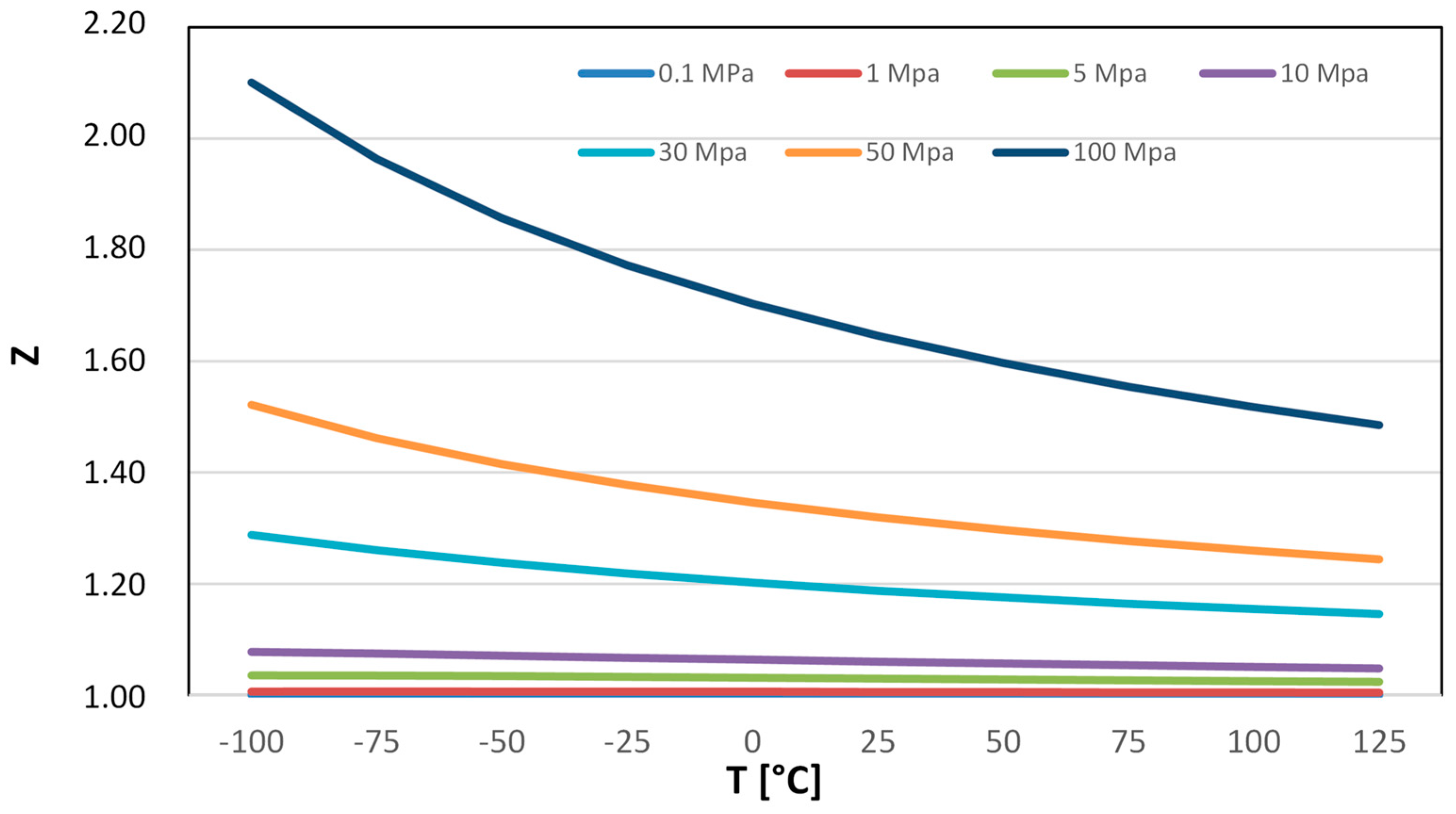
Appendix A of the present paper. A substantial increase in density is associated with the application of high pressure and a simultaneous reduction in temperature. This correlation underscores the dynamic interplay between these thermodynamic factors, providing valuable insights for optimizing hydrogen storage and utilization strategies. As seen by consulting the data available in
Appendix A, hydrogen density experiences a significant increase at higher pressure and lower temperatures. Density values cannot be easily calculated using the ideal gas equation of state, since hydrogen exhibits behavior more characteristic of a real gas, but it could be evaluated using the values of the compressibility factor (Z), a dimensionless quantity that reflects how much the gas deviates from ideal behavior.
Compressed hydrogen storage encompasses a spectrum of pressure levels tailored for diverse applications. Small-scale storage, utilizing spherical vessels, commonly operates at 20 bars. Medium-scale storage in pipelines typically involves a pressure of 100 bar, while industrial-scale storage utilizes pressures in the range of 200–300 bar up to 1000 bar. Determining the optimal compression pressure for storing hydrogen in gaseous form is a nuanced challenge, requiring a compromise between energy considerations, aiming to minimize the impact on compression work and economic and safety factors. The latter involves ensuring that containers do not incur excessive costs due to structural requirements and materials. Identifying an optimum point among these diverse objectives becomes crucial for each application, underscoring the need for a tailored approach. It is evident that pursuing a specific objective aligned with the unique characteristics of each application is imperative to address the complexities inherent in hydrogen storage.
3. Gaseous Hydrogen Compression: Analysis of Technological Solutions Available
Hydrogen compression in gaseous form plays a crucial role in various applications, including hydrogen storage, transportation, and energy conversion. Various methods for hydrogen compression are used. Each of them has their own unique characteristics, advantages, and drawbacks [
18].
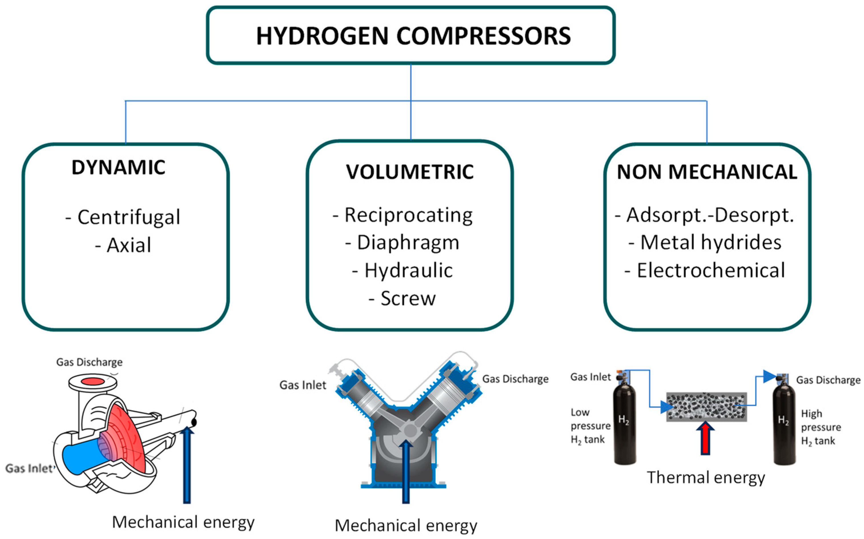
Figure 4 summarizes the major compression technologies used for hydrogen applications, illustrating the types of energy required for achieving the desired pressure levels: mechanical or thermal. Volumetric technologies, such as reciprocating piston compressors, diaphragm/hydraulic/ionic compressors, and screw compressors, involve compressing a gas volume within a control volume and then discharging it at increased pressure. Another mechanical option is represented by dynamic compression (using centrifugal ore compressors), in which kinetic energy is added to the inlet gas stream. While industrial references for centrifugal compressors on pure hydrogen are lacking, this remains an active field of development. Additionally, non-mechanical compression methods, including electrochemistry or the adsorption/absorption of hydrogen into porous materials, are of interest [
19,
20].
Table 2 aims to summarize the primary features of these various compression methods, offering a comprehensive overview. Diaphragm compressors use flexible diaphragms to compress the gas, while screw compressors utilize rotating screws to decrease the volume of the gas.
Hydrogen compression presents not only an energy challenge but also a concern for material integrity. Hydrogen can induce embrittlement in metallic materials, reducing their ductility despite maintaining their strength. This poses potential fracture risks from both a fracture mechanics and fit-for-service standpoint, as defects may become unstable.
Despite some technologies already being commercial, there is considerable debate surrounding the investigation of more widespread and advanced products to achieve pressures ranging from 80 to 100 MPa, suitable for both stationary and mobile applications. Small-scale storage using spherical vessels commonly operates at 2 MPa. Medium-scale storage in pipes typically involves a pressure of 10 MPa [
21,
22]. Industrial-scale storage utilizes pressures in the range of 20–30 MPa [
23]. High operational pressures for light- and heavy-duty road transport span from 35 to 70 MPa [
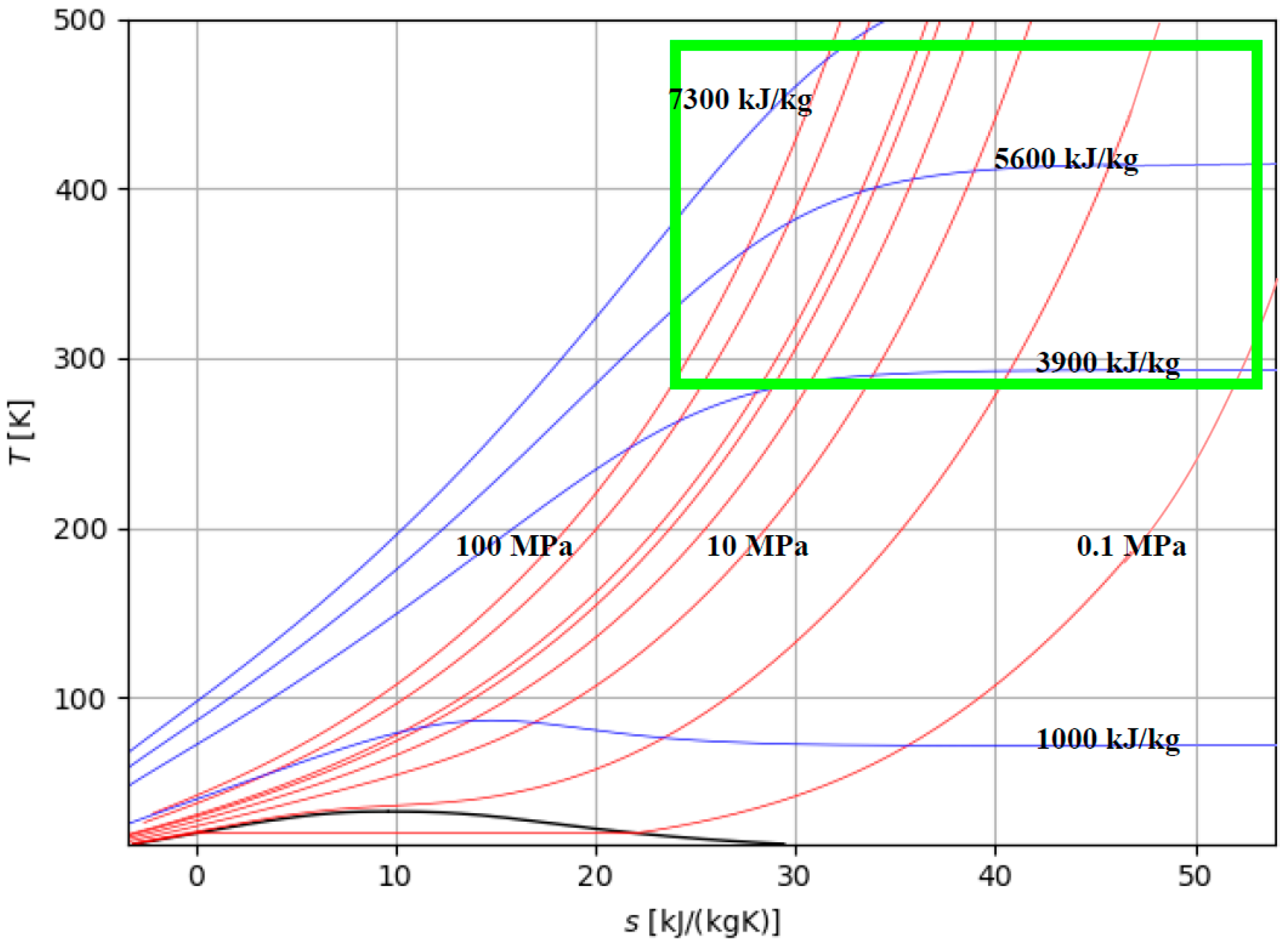
24]. In some cases, such as hydrogen refueling stations or large production areas, the compression of hydrogen up to 100 MPa may be required. The isobaric and isenthalpic curves of interest for the storage of H
2 in compressed gaseous form are qualitatively represented in
Figure 5.
The area of interest is identified by the minimum and maximum pressure and temperature values of the compression solutions discussed in this paper, i.e., pressure in the range of 0.1–100 MPa and temperature of 15–215 °C (
Figure 5). The analysis of several compressors available on the market reveals that the maximum pressure level reached is approximately 450 bar, with the most commonly used pressure being around 350 bar. These compressors are of the volumetric type, typically consisting of three or four stages, although compressors with five stages are also available, albeit with lower power ratings and reduced mass flow rates.
Table 3 presents some data that can be extracted from technical catalogues by various manufacturers, such as [
25,
26]. Compressors with maximum output pressures of 700 bar are not commercially available in the market. Based on the data provided in
Table 3, rearranged from available commercial data and referencing a total compression ratio of 350, the specific work associated with compression varies from approximately 10 MJ/kg for larger-sized compressors to over 26 MJ/kg for smaller-sized compressors. The nominal power of the various available models ranges from 3 kW up to 230 kW, and the number of stages ranges from 2 to 5. The values of the specific works required for compression are estimated in the last column of the table and are estimated by the authors based on the data reported by the manufacturers. As can be seen, they are dependent on the overall compression ratio and are a decidedly significant fraction of the calorific value of the fuel.
4. Compression Model and Energy Requirements for Hydrogen Compression: Sensitivity Analysis
Compressing hydrogen into the gaseous form is conceptually quite simple, but it demands a significant energy input. In this section, we explore the modeling of hydrogen compression, focusing on the comparison between idealized isothermal compression and real-world compression processes. We begin by examining the theoretical framework of isothermal compression, where the compression process occurs at a constant temperature. Under ideal conditions, isothermal compression requires a minimal amount of energy input, as dictated by the ideal gas law. However, real-world compression systems deviate from ideal behavior due to factors such as friction, heat transfer, and inefficiencies inherent in mechanical components. Through mathematical modeling and simulation, we investigate how these deviations impact the energy requirements of hydrogen compression. By comparing the energy expenditure of idealized isothermal compression with real-world compression processes, we aim to quantify the efficiency losses associated with practical compression systems. This analysis provides valuable insights into the thermodynamic limitations and performance characteristics of hydrogen compression technologies. From a thermodynamic perspective, the process of isothermal reversible compression requires the least amount of work. This can be computed under the assumption of ideal gas behavior, using the following equation [
10], from thermodynamic state 1 to thermodynamic state 2:
So, the energy required to obtain a final pressure of 700 bar, starting from temperature of 300 K, is about 8.17 MJ/kg, while it is 7.30 MJ/kg for compression at 350 bar.
The evaluation provided by Equation (2) only gives a rough estimation of the minimum energy required to achieve the desired pressure, as it does not account for the non-ideal behavior of the gas. This non-ideal behavior becomes more pronounced as the final pressure increases. From a technical point of view, two pressure levels are known at which compressions are made: 350 bar in the case of small- and medium-sized applications and 700 bar in the case of larger-sized applications. Obviously, none of these pressures can be obtained with a single compression step since, from a technological point of view, it is difficult to think of going beyond a compression ratio of 7. Therefore, starting from the atmospheric pressure, to obtain a final value of 350 bar, at least three stages are necessary. To reach 700 bars, at least four compression levels are required. However, since the compressions are irreversible adiabatic and cause an increase in temperature, it is necessary to remain below a certain temperature level (200 °C). In practical scenarios, the temperature of hydrogen undergoes a considerable increase even when utilizing advanced multi-stage intercooling technology during compression. As a result, it is more accurate to characterize the compression process as polytropic compression. The energy consumption for this type of process can be determined by the following equation, using a polytropic exponent,
n, that, in accordance with the most disseminated textbooks of thermodynamics, can be assumed, according to the considerations contained in [
10], to be
n = 1.36.
The use of a polytropic index lower than 1.4 is also in line with the idea that the cooling system can be active during compression. As evidenced by the data presented in
Table 4, the findings indicate a significant overestimation of compression work, particularly noticeable when targeting higher pressures. This underscores the necessity for a multi-stage compression approach with intercooling, rather than simple polytropic compression with index n, which would result in excessively high specific work requirements and compression temperatures well above ambient levels. Moreover, the result reported in the fourth column of
Table 4 is an underestimated value of the specific work required for compression, as it does not consider the compressibility factor Z which would make the specific work even higher.
If one approaches the evaluation of the compression process as if it were isothermal, two crucial elements are overlooked. On the one hand, there might be a temptation to increase the compression pressure, leading to a significant rise in hydrogen density. On the other hand, the full understanding of the energy expenditure associated with the storage process would not be fully grasped. Due to the limitation of a pressure ratio of approximately 7 for each stage, achieving a pressure level of 350 bar necessitates three to five compression stages, while reaching 700 bars would require at least four stages. Equation (3) suggests that, with perfect intercooling, where the gas returns to its initial temperature before each subsequent compression stage, the literature estimates indicate that the minimum compression work can reach 10.2 MJ/kg (calculated using a polytropic index of
n = 1.36, considering the concurrent action of the refrigeration system), as referenced in [
10]. This value represents a 25% increase compared to what is needed for an ideal isothermal process. However, the situation is further complicated by real gas behavior.
Considering both the number of compression stages,
N, the compressibility factor of hydrogen,
Z, and an isentropic efficiency of compression,
his, the compression work can be better evaluated with the following:
The practical energy consumption for hydrogen compression in real application typically exceeds the theoretical minimum by at least 2.5 times. Consequently, in the case of reaching 700 bars, it can be higher than 20 MJ/kg, marking an unsustainable level, especially when considering it constitutes more than 15% of the calorific value. A more accurate assessment can be made by considering the differences in enthalpy at various compression stages, considering plausible values for isentropic efficiency.
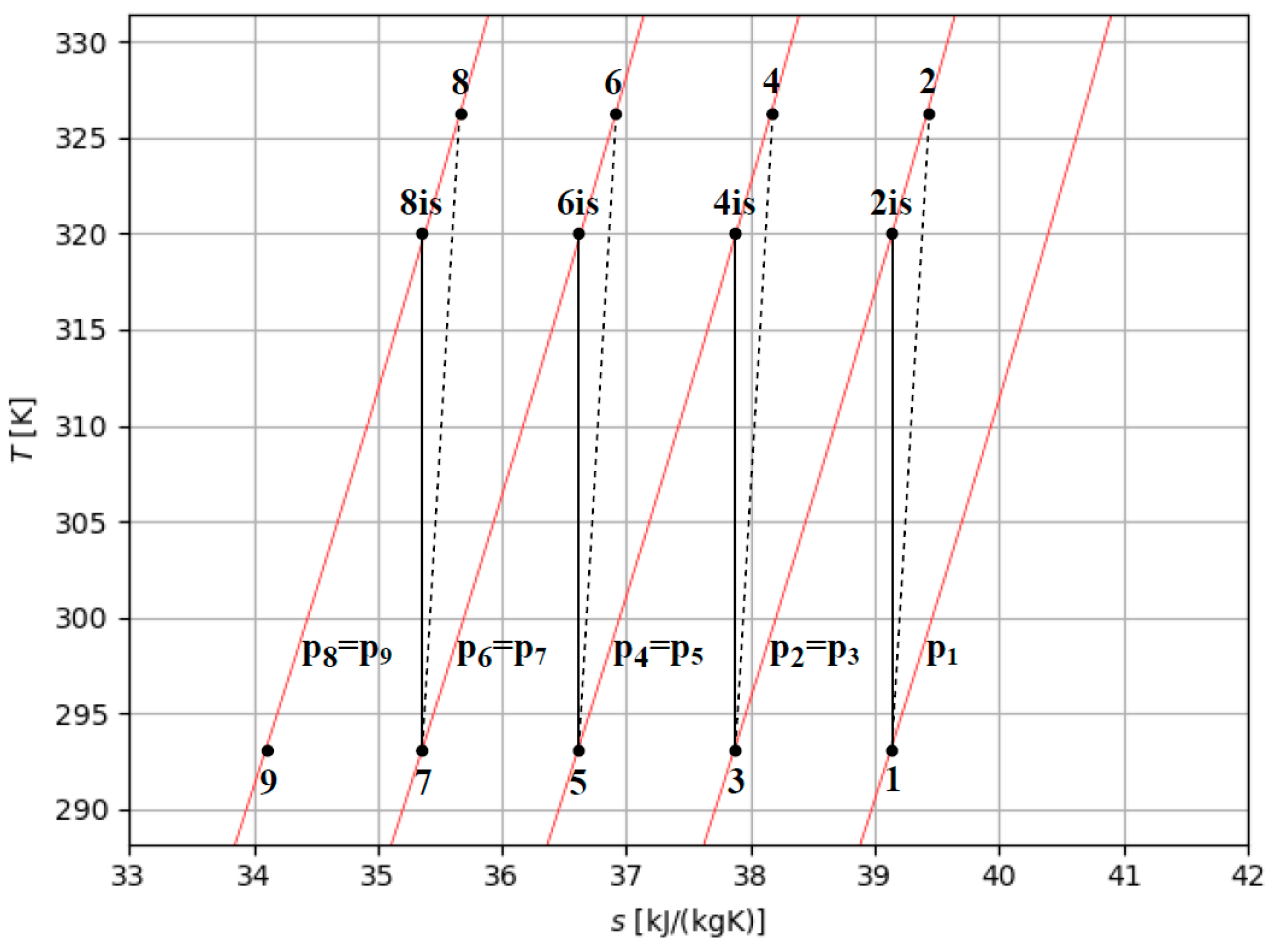
Figure 6 shows the temperature–entropy diagram of intercooled multi-stage compression with four stages of compression, where
p1 is the initial pressure of hydrogen to store and
p8 equals the storage pressure desired (
pst). The work of compression per kg of hydrogen in an intercooled multi-stage process (
wm−s) can be evaluated by the sum of the enthalpy changes between the stages. In intercooled multi-stage compression, the specific work (
wm−s) can be evaluated, as schematically referred to in
Figure 6 by the isentropic efficiency (
ηis) of the compressor, where four compression stages are referred to, as follows:
and in general
The power of compressor is estimated considering the mass flow rate,
m, as follows:
In general, to estimate the compression work, it is necessary to define the intermediate pressures (pint), i.e., the pressures at which the gas is intercooled between two stages.
Thus, for example,
pint,1 equals the final pressure of the first stage and the initial pressure of the second stage of compression. The intermediate pressures can be selected using the following:
where
N is considered as the total number of compression stages and the initial compression pressure (
Pin) equals 1 bar.
This choice can minimize the maximum temperature reached during compression and the specific work (
wm−s) necessary as the storage pressure and the number of stages vary. To reach a well-defined pressure, the compression work is minimized when all the stages have the same compression ratio (
β), so that
Therefore, the intermediate pressures minimizing the work of a multi-stage intercooled compression that has stages with the same isentropic efficiency can be defined as follows:
In the context of hydrogen gas compression processes, it is important to consider that if hydrogen is introduced at environmental pressure (1 bar), the maximum compression ratio cannot exceed 7. This means that to achieve a pressure level of 350 bar, at least three compression stages are required (1–7, 7–49, 49–343 bar). However, another significant factor to consider is the maximum temperature during compression, which should ideally not exceed 150–200 °C to avoid hydrogen embrittlement issues. Consequently, the maximum compression ratio between stages should not exceed five. Therefore, in practical technical solutions, reaching a pressure level of 350 bar is commonly associated with the use of at least four compression stages, theoretically allowing for pressure levels of approximately 625 bar (1–5, 5–25, 25–125, 125–625 bar). Reaching a pressure level of 700 bar or more requires at least five stages of compression.
5. Analysis of the Real Compression Work with Respect to the Various Combinations of Initial and Final Pressure
In this section, the authors present some evaluations based on the model developed in
Section 4, aimed at understanding the energy cost of compression processes under conditions as close to real as possible. To achieve this, it is necessary to assume a plausible value for the isentropic compression efficiency. There is limited literature available concerning isentropic efficiency for H
2 compressors, but depending on the compressor type, size (scale), and design, this value varies in the range of ~55–80% for most compressor designs, according to [
11,
14,
22]. Therefore, considering an isentropic compression efficiency of 0.8 and assuming perfect intercooling, along with the initial pressure of the hydrogen and the desired pressure at the end of the process, as well as the maximum temperature achievable due to structural constraints, it follows the need to determine the optimal number of compression stages. As observed in
Table 5, in terms of the specific work required for gas compression, the difference between using two, three, or four compression stages is not particularly relevant. However, what is noteworthy is the maximum temperature: while with two stages, it reaches approximately 217 °C, three or four stages allow for much greater limitation of the maximum temperature. Similar considerations can be made if a final gas pressure of 10 MPa is required; in this scenario, it is not feasible to use only two compression stages since the compression ratio would be approximately 10 (
Table 6). The situation becomes more complicated if aiming to achieve a final pressure of 350 bar. In this case, maintaining reasonable value of maximum temperature requires four or five compression stages. The compression work required is about 11 MJ/kg, a value that is approximately 10% of the fuel’s calorific value.
Table 7 shows the data related to the two cases with four or five compression stages. Obviously, the specific energy required for compression increases as the isentropic compression efficiency decreases.
Table 8 illustrates the specific work necessary if the isentropic efficiency is 0.7. In this case, the maximum temperature and the specific work of compression increases with respect to the cases analyzed in
Table 5,
Table 6 and
Table 7.
As shown in
Table 8, decreasing the isentropic efficiency from 0.8 to 0.7 results in both an increase in the specific work required for compression and a rise in the maximum temperature. The evaluations we have made up to this point consider, for the sake of homogeneity, an initial hydrogen pressure of 1 bar. However, utilizing an initial compression pressure higher than 1 bar can be advantageous for reducing both the specific compression work and the maximum temperatures reached. In the case of hydrogen production using electrolyzers, the inlet pressure in the compression system can be even higher. Commercial electrolyzers typically produce hydrogen with pressures ranging from 1 to 35 bar. Utilizing a higher inlet pressure results in a reduction in the work required for compression and potentially in the number of compression stages needed. For instance, considering an inlet pressure of 30 bar (feasible for hydrogen after the electrolysis process), significant reductions in both the specific compression work and the maximum temperature, as well as the number of stages required, can be achieved.
Table 9 shows, for example, the date relative to three different values of the final pressures in particular,
pst = 350, 700, or 1000 bar, which are typical values for high size storage infrastructures, like hydrogen re-fueling stations, as discussed in
Section 3. Referring to the previously developed sensitivity analysis, we have established that the compression of hydrogen necessitates an additional energy input, particularly noteworthy when dealing with substantial pressure increases, amounting to approximately 10% of the calorific value of hydrogen if a pressure ratio of 700:1 is considered. This factor gains even more significance when considering that a portion of the energy has already been dissipated during the electrolysis process. It is crucial to emphasize, however, that the energy expenditure during the compression phase does not escalate significantly in relation to the compression ratio.
This implies that the selection of an optimal compromise between enhancing density and minimizing work input might be contingent on other critical factors. These factors include the maximum number of compression stages, the upper limit on compression temperature, and the maximum compression ratio associated with a single stage. Balancing these elements becomes important in determining the overall efficiency and feasibility of hydrogen compression processes. Analyzing all the data related to the specific work for compressing hydrogen in gaseous form, wm−s, it can be observed that this is estimable, depending on the case, at a percentage ranging between 40% and 67%, higher than the ideal work achievable in an isothermal compression according to Equation (2), wiT,id.
Comparing the values reported in the previous tables with those from commercial systems available on the market, it is evident that the specific compression work values estimated from the catalog data (see
Table 3) are significantly higher than those derived from theoretical evaluations like ours. This suggests that the actual isentropic compression efficiency may be lower than the considered values (0.7–0.8), possibly around 0.5–0.55. However, it is clear that achieving higher isentropic efficiencies may be linked to larger compressors, which is therefore conceivable.
As relevant concluding remarks of the analysis, we can summarize the following main elements. The compression of hydrogen in the gaseous form requires relevant energy input, and for significant pressures, this energy input is approximately 10% of the calorific value of hydrogen. This is particularly notable, especially considering that a portion of the energy is already dissipated for hydrogen production, as, for example, in the electrolysis process. It is important to highlight that the energy spent during the compression phase does not increase proportionally with the compression ratio. This suggests that the choice of an optimal compromise between increasing density and minimizing work input depends on several factors beyond the compression ratio itself.
The selection of an optimal compromise hinges on other relevant elements such as the maximum number of compression stages and also involves considerations of the maximum compression temperature and the maximum compression ratio associated with a single stage. Balancing all of these elements is crucial for determining the overall efficiency and feasibility of hydrogen compression processes. This underscores the need for a nuanced approach that considers multiple factors in achieving an effective and sustainable compression strategy for hydrogen.
Finally, we have seen how reaching a maximum pressure level of 700 bar is quite reasonable: lower pressure levels do not seem particularly advantageous, considering that the energy extracted from the process is not significantly higher than that required to achieve a pressure level of 350 bar. Of course, we must also consider that the energy expended for compression is energy withdrawn from the energy chain. Indeed, thinking about a system like the one depicted in
Figure 1, hydrogen storage can be justified only by the need to introduce greater flexibility into the energy system, and gaseous storage appears to be the most relevant. However, in terms of energy balance, of the 120 MJ contained in one unit of hydrogen mass, at least 40 MJ is dissipated in the electrolysis process (Franco and Giovannini, in [
27]) and 10–15 MJ is additionally consumed in the compression phase. This means that more than 40–45% of the renewable energy converted is lost in the chain before utilization. The quantity would certainly be higher when considering storage in liquid form. Therefore, optimizing techniques for storing hydrogen in gaseous form is certainly an important objective, but it is still important to keep in mind that the use of storage must always be carefully evaluated.


