

Investigation of Diffusible Hydrogen Concentration in Gas Metal Arc Brazing by Carrier Gas Hot Extraction Method Referring to ISO 3690

Abstract
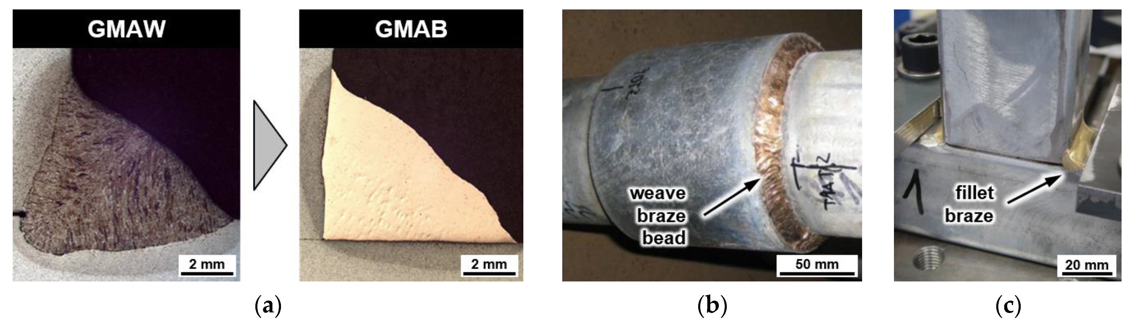
:1. Introduction
2. Hydrogen Analysis
3. Materials and Methods
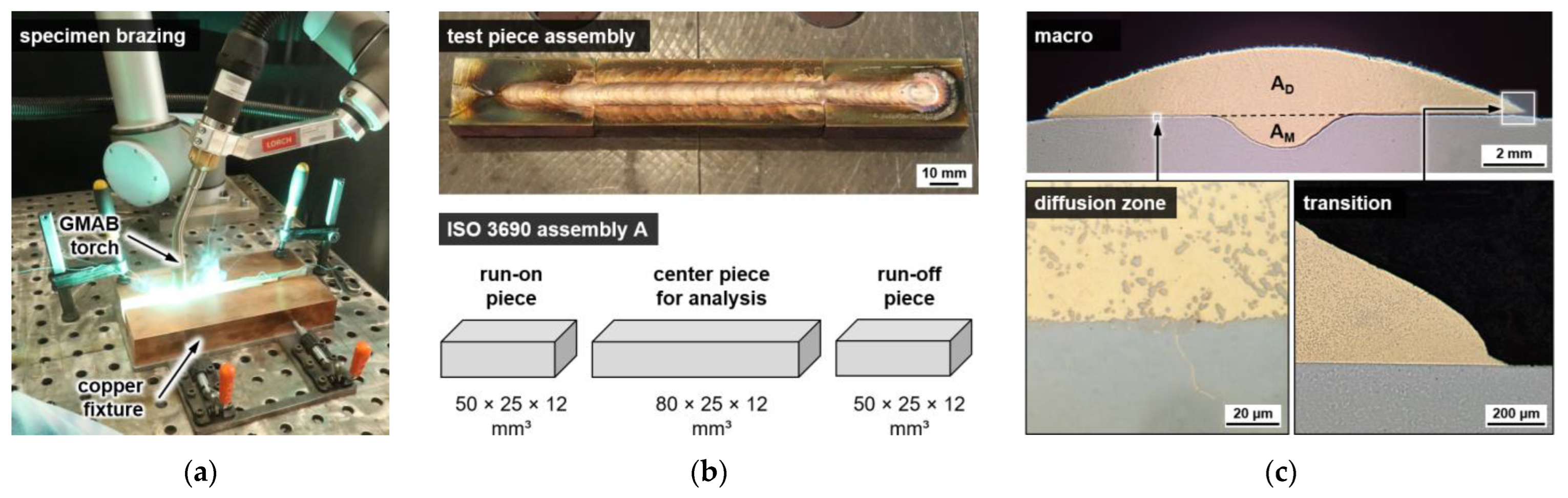
3.1. Sample Preparation
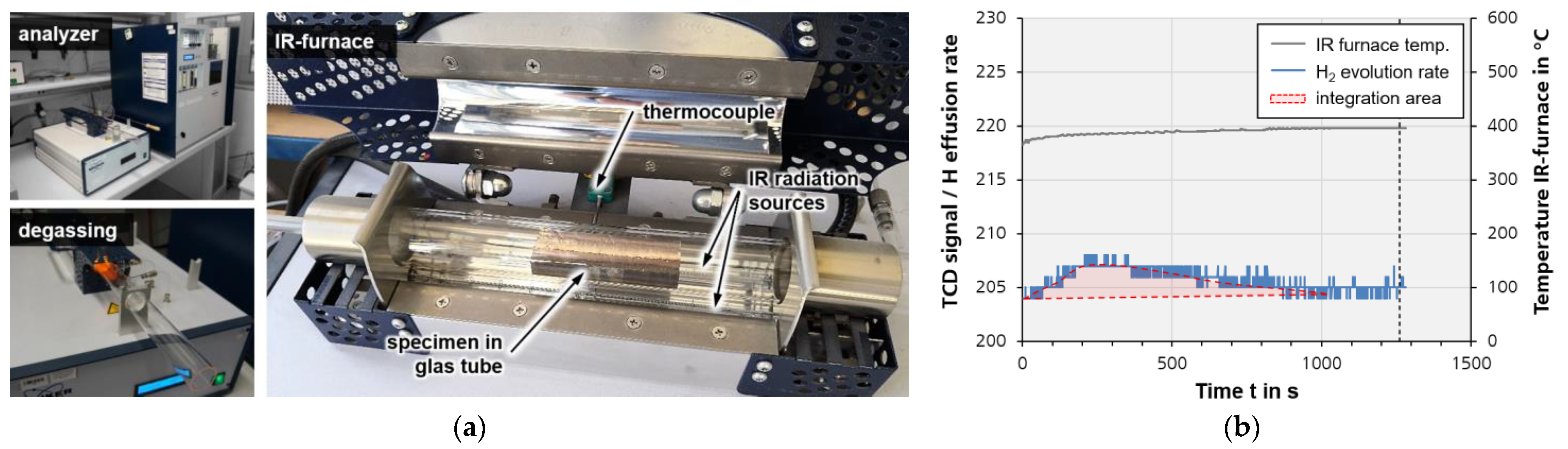
3.2. Measurement of Hydrogen
4. Results and Discussion
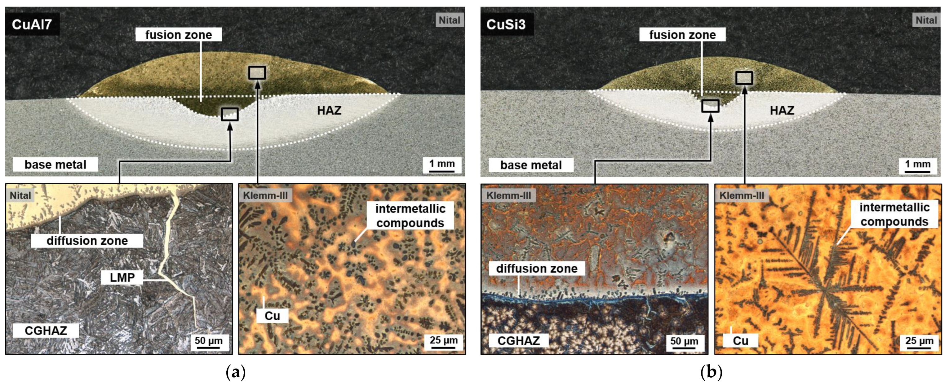
4.1. Metallography
4.2. Hydrogen Content
5. Conclusions and Outlook
- The methodology for hydrogen determination in GMAW weld metal according to ISO 3690 can generally be applied for GMAB as well.
- For arc brazed beads, low diffusible hydrogen concentrations in the range of HD = 0.1 to 0.3 mL/100 g were found.
- Due to characteristically low base metal penetration in GMAB compared to arc welding, the hydrogen concentration in the entire fused metal HF is only about 5 to 18% lower than the corresponding hydrogen concentration in deposit metal.
Author Contributions
Funding
Institutional Review Board Statement
Informed Consent Statement
Data Availability Statement
Conflicts of Interest
Abbreviations
| CGHE | Carrier gas hot extraction |
| FCAW | Flux-cored arc welding |
| FGHAZ | Fine-grained heat-affected zone |
| GCHAZ | Grain-coarsened heat-affected zone |
| GMAB | Gas metal arc brazing |
| GMAW | Gas metal arc welding |
| HACC | Hydrogen-assisted cold cracking |
| HAZ | Heat-affected zone |
| ICHAZ | Intercritical heat-affected zone |
| LMP | Liquid metal penetration |
| MSG | Metal shielding gas (welding/brazing/soldering) |
| TCD | Thermal conductivity detector |
| TDA | thermal desorption analysis |
References
- ISO 4063:2010-03; Welding and Allied Processes–Nomenclature of Processes and Reference Numbers. International Organization for Standardization: Vernier, Geneva, Switzerland, 2010.
- Pikuła, J.; Pfeifer, T.; Mendakiewicz, J. Influence of the shielding gas on the properties of VP MIG/MAG braze-welded joints in zinc coated steel sheets. Bull. Inst. Weld. 2014, 1, 35–41. [Google Scholar] [CrossRef]
- Schwartz, M.M. Brazing–Second Edition; ASM International: Materials Park, OH, USA, 2003; ISBN 0-87170-784-5. [Google Scholar]
- Nalajala, D.; Mookara, R.K.; Amirthalingam, M. Gas metal arc brazing behaviour of a galvanised advanced high strength steel in short circuiting and short circuiting with pulsing modes. Weld. World 2021, 66, 69–80. [Google Scholar] [CrossRef]
- Andreazza, P.; Gericke, A.; Henkel, K.-M. Investigations on arc brazing for galvanized heavy steel plates in steel and shipbuilding. Weld. World 2021, 65, 1199–1210. [Google Scholar] [CrossRef]
- Gericke, A.; Drebenstedt, K.; Kuhlmann, U.; Henkel, K. Improvement of fatigue strength in heavy steel constructions through arc brazing. ce/papers 2021, 4, 1118–1125. [Google Scholar] [CrossRef]
- DNV-CG-0129; Class Guideline–Fatigue Assessment of Ship Structures. DNV AS: Bærum, Norway, 2021.
- Bailey, N.; Coe, F.R.; Gooch, T.G.; Hart, P.H.M.; Jenkins, N.; Pargeter, R.J. Welding Steels without Hydrogen Cracking, 2nd ed.; Woodhead Publishing Limited: Cambridge, UK, 2004; ISBN 978-1-85573-014-6. [Google Scholar]
- Lippold, J.C. Welding Metallurgy and Weldability; John Wiley & Sons, Inc.: Hoboken, NJ, USA, 2014; ISBN 978-1-11823-070-1. [Google Scholar]
- Christ, M.; Guo, X.; Sharma, R.; Li, T.; Bleck, W.; Reisgen, U. Hydrogen Embrittlement Susceptibility of Gas Metal Arc Welded Joints from a High-Strength Low-Alloy Steel Grade S690QL. Steel Res. Int. 2020, 91, 2000131. [Google Scholar] [CrossRef]
- Robertson, I.M.; Sofronis, P.; Nagao, A.; Martin, M.L.; Wang, S.; Gross, D.W.; Nygren, K.E. Hydrogen Embrittlement Understood. Met. Mater. Trans. B 2015, 46, 1085–1103. [Google Scholar] [CrossRef]
- Wilhelm, E.; Mente, T.; Rhode, M. Waiting time before NDT of welded offshore steel grades under consideration of delayed hydrogen-assisted cracking. Weld. World 2021, 65, 947–959. [Google Scholar] [CrossRef]
- Schaupp, T.; Schroeder, N.; Schroepfer, D.; Kannengiesser, T. Hydrogen-Assisted Cracking in GMA Welding of High-Strength Structural Steel—A New Look into This Issue at Narrow Groove. Metals 2021, 11, 904. [Google Scholar] [CrossRef]
- Schaupp, T.; Rhode, M.; Yahyaoui, H.; Kannengiesser, T. Influence of heat control on hydrogen distribution in high-strength multi-layer welds with narrow groove. Weld. World 2018, 63, 607–616. [Google Scholar] [CrossRef]
- Qu, J.; Feng, M.; An, T.; Bi, Z.; Du, J.; Yang, F.; Zheng, S. Hydrogen-Assisted Crack Growth in the Heat-Affected Zone of X80 Steels during in Situ Hydrogen Charging. Materials 2019, 12, 2575. [Google Scholar] [CrossRef]
- Magnusson, H.; Frisk, K. Diffusion, Permeation and Solubility of Hydrogen in Copper. J. Phase Equilibria Diffus. 2017, 38, 65–69. [Google Scholar] [CrossRef]
- Peñalva, I.; Alberro, G.; Legarda, F.; Esteban, G.A.; Riccardi, B. Interaction of Copper Alloys with Hydrogen. In Copper Alloys-Early Applications and Current Performance-Enhancing Processes; Collini, L., Ed.; IntechOpen: London, UK, 2012. [Google Scholar] [CrossRef] [Green Version]
- Marchi, C.S.; Somerday, B.P. Technical Reference on Hydrogen Compatibility of Materials; SAND2012-7321; Sandia National Laboratories: Livermore, CA, USA, 2012. [Google Scholar]
- Kannengiesser, T.; Tiersch, N. Measurements of Diffusible Hydrogen Contents at Elevated Temperatures using Different Hot Extraction Techniques—An International Round Robin Test. Weld. World 2010, 54, R115–R122. [Google Scholar] [CrossRef]
- Rhode, M.; Schaupp, T.; Muenster, C.; Mente, T.; Boellinghaus, T.; Kannengiesser, T. Hydrogen determination in welded specimens by carrier gas hot extraction—A review on the main parameters and their effects on hydrogen measurement. Weld. World 2019, 63, 511–526. [Google Scholar] [CrossRef]
- ISO 3690:2018-07; Welding and Allied Processes-Determination of Hydrogen Content in Arc Weld Metal. International Organization for Standardization: Vernier, Geneva, Switzerland, 2018.
- Mente, T.; Boellinghaus, T.; Schmitz-Niederau, M. Heat treatment Effects on The Reduction of Hydrogen in Multi-Layer High-Strength Weld Joints. Weld. World 2012, 56, 26–36. [Google Scholar] [CrossRef]
- Nevasmaa, P. Prevention of Weld Metal Hydrogen Cracking in High-Strength Multipass Welds. Weld. World 2004, 48, 2–18. [Google Scholar] [CrossRef]
- Padhy, G.K.; Komizo, Y. Diffusible Hydrogen in Steel Weldments: A Status Review. Trans. JWRI 2013, 42, 39–62. [Google Scholar]
- Świerczyńska, A.; Fydrych, D.; Łabanowski, J. The Effect of Welding Conditions on Diffusible Hydrogen Content in Deposited Metal. Solid State Phenom. 2011, 183, 193–200. [Google Scholar] [CrossRef]
- Kannengiesser, T.; Lausch, T. Diffusible Hydrogen Content Depending on Welding and Cooling Parameters. Weld. World 2012, 56, 26–33. [Google Scholar] [CrossRef]
- Padhy, G.K.; Ramasubbu, V.; Murugesan, N.; Remash, C.; Albert, S.K. Effect of preheat and post-heating on diffusible hydrogen content of welds. Sci. Technol. Weld. Join. 2012, 17, 408–413. [Google Scholar] [CrossRef]
- ISO 24373:2018-11; Welding Consumables–Solid Wires and Rods for Fusion Welding of Copper and Copper Alloys-Classification. International Organization for Standardization: Vernier, Geneva, Switzerland, 2018. [CrossRef]
- EN 10027-2:2015; Designation Systems for Steels–Part 2: Numerical System. CEN-CENELEC: Brussels, Belgium, 2015.
- ISO 17639:2022-01; Destructive Tests on Welds in Metallic Materials-Macroscopic and Microscopic Examination of Welds. International Organization for Standardization: Vernier, Geneva, Switzerland, 2022.
- Lee, S.J.; Sharma, A.; Jung, D.H.; Jung, J.P. Influence of Arc Brazing Parameters on Microstructure and Joint Properties of Electro-Galvanized Steel. Metals 2019, 9, 1006. [Google Scholar] [CrossRef] [Green Version]
- Savage, W.F.; Nippes, E.F.; Stanton, R.P. Intergranular Attack of Steel by Molten Copper. Weld. J. 1978, 57, 9–16. [Google Scholar]
- Chen, S.; Yu, X.; Huang, J.; Yang, J.; Lin, S. Interfacial ferrite band formation to suppress intergranular liquid copper penetration of solid steel. J. Alloys Compd. 2019, 773, 719–729. [Google Scholar] [CrossRef]


| Material | Cu | Al | Fe | Mn | Ni + Co | P | Pb | Si | Sn | Zn | |
|---|---|---|---|---|---|---|---|---|---|---|---|
| filler 1 CuSi3Mn1 | (n = 3) | 95.95 | <0.0010 | 0.062 | 0.82 | 0.013 | 0.0078 | <0.0010 | 2.91 | 0.0040 | <0.0015 |
| (sx) | (0.04) | (0.0003) | (0.008) | (0.01) | (0.001) | (0.0003) | (0.0005) | (0.05) | (0.0000) | (0.0005) | |
| filler 2 CuAl7 | (n = 3) | 85.68 | 7.73 | 2.14 | 1.43 | 2.42 | 0.018 | 0.029 | 0.050 | 0.0074 | <0.0015 |
| (sx) | (0.20) | (0.07) | (0.07) | (0.04) | (0.02) | (0.001) | (0.004) | (0.022) | (0.0009) | (0.0019) | |
| C | Si | Mn | Cr | Mo | V | Ni | Cu | Al | Fe | ||
| base metal 1.0570 | (n = 10) | 0.065 | 0.311 | 1.36 | 0.022 | <0.0010 | <0.0010 | 0.0138 | 0.013 | 0.048 | 98.08 |
| (sx) | (0.0075) | (0.012) | (0.013) | (0.0003) | (0.0002) | (0.0002) | (0.0003) | (0.0045) | (0.0005) | (0.023) |
| Sample/Series | Polarity | Voltage 1 U in V | Current 1 I in A | Brazing Speed v in m/min | Arc Energy 2 E in kJ/mm |
|---|---|---|---|---|---|
| A: CuSi3Mn1 high energy | ~AC | 30.6 | 204 | 0.45 | 0.83 |
| B: CuSi3Mn1 low energy | ~AC | 27.6 | 158 | 0.45 | 0.58 |
| C: CuAl7 high energy | ~AC | 32.0 | 195 | 0.45 | 0.83 |
| D: CuAl7 low energy | ~AC | 30.5 | 144 | 0.45 | 0.58 |
| Sample | Deposited Metal | Fused Metal | Diffusible Hydrogen | ||||
|---|---|---|---|---|---|---|---|
| mD in g | AD in mm2 | AF in mm2 | VSTP in mL | HD in mL/100 g | HF in ppm | ||
| A CuSi3Mn1 high energy | 1 2 3 (sx) | 9.02 9.29 7.11 8.47 (1.19) | 14.35 15.35 14.90 14.87 (0.50) | 16.54 17.40 17.31 17.08 (0.47) | 0.041 0.011 0.019 0.024 (0.016) | 0.46 0.12 0.27 0.28 (0.17) | 0.36 0.09 0.21 0.22 (0.13) |
| B CuSi3Mn1 low energy | 1 2 3 (sx) | 5.87 6.04 6.07 5.99 (0.11) | 9.11 9.57 9.40 9.36 (0.23) | 9.71 10.51 10.62 10.28 (0.50) | 0.009 0.004 0.013 0.009 (0.005) | 0.16 0.06 0.21 0.14 (0.08) | 0.13 0.05 0.17 0.12 (0.06) |
| C CuAl7 high energy | 1 2 3 (sx) | 10.69 9.91 9.83 10.14 (0.48) | 15.36 15.12 15.49 15.32 (0.19) | 18.41 18.14 18.75 18.43 (0.31) | 0.001 0.009 0.053 0.021 (0.028) | 0.01 0.09 0.54 0.21 (0.29) | 0.01 0.07 0.40 0.16 (0.21) |
| D CuAl7 low energy | 1 2 3 (sx) | 6.58 6.14 6.42 6.38 (0.22) | 8.60 9.33 8.68 8.87 (0.40) | 9.36 9.56 9.56 9.49 (0.12) | 0.013 0.042 0.006 0.020 (0.019) | 0.19 0.68 0.10 0.32 (0.31) | 0.16 0.59 0.08 0.28 (0.28) |
Disclaimer/Publisher’s Note: The statements, opinions and data contained in all publications are solely those of the individual author(s) and contributor(s) and not of MDPI and/or the editor(s). MDPI and/or the editor(s) disclaim responsibility for any injury to people or property resulting from any ideas, methods, instructions or products referred to in the content. |
© 2022 by the authors. Licensee MDPI, Basel, Switzerland. This article is an open access article distributed under the terms and conditions of the Creative Commons Attribution (CC BY) license (https://creativecommons.org/licenses/by/4.0/).
Share and Cite
Brätz, O.; Ripsch, B.; Gericke, A.; Henkel, K.-M. Investigation of Diffusible Hydrogen Concentration in Gas Metal Arc Brazing by Carrier Gas Hot Extraction Method Referring to ISO 3690. Hydrogen 2023, 4, 1-10. https://doi.org/10.3390/hydrogen4010001
Brätz O, Ripsch B, Gericke A, Henkel K-M. Investigation of Diffusible Hydrogen Concentration in Gas Metal Arc Brazing by Carrier Gas Hot Extraction Method Referring to ISO 3690. Hydrogen. 2023; 4(1):1-10. https://doi.org/10.3390/hydrogen4010001
Chicago/Turabian StyleBrätz, Oliver, Benjamin Ripsch, Andreas Gericke, and Knuth-Michael Henkel. 2023. "Investigation of Diffusible Hydrogen Concentration in Gas Metal Arc Brazing by Carrier Gas Hot Extraction Method Referring to ISO 3690" Hydrogen 4, no. 1: 1-10. https://doi.org/10.3390/hydrogen4010001